Download Liebert PEX User Manual - Large Frame

Transcript
TABLE OF CONTENTS
IMPORTANT SAFETY INSTRUCTIONS . . . . . . . . . . . . . . . . . . . . . . . . . . . . . . . . . . . . . . . . . . . . . . . .1
1.0
LIEBERT PEX COMPONENTS AND NOMENCLATURE
2.0
COOLING CONFIGURATIONS
3.0
PRE-INSTALLATION GUIDELINES
3.1
Room Preparation. . . . . . . . . . . . . . . . . . . . . . . . . . . . . . . . . . . . . . . . . . . . . . . . . . . . . . . . . . . . 9
3.2
Air Distribution . . . . . . . . . . . . . . . . . . . . . . . . . . . . . . . . . . . . . . . . . . . . . . . . . . . . . . . . . . . . . 9
3.2.1
3.2.2
Downflow Units . . . . . . . . . . . . . . . . . . . . . . . . . . . . . . . . . . . . . . . . . . . . . . . . . . . . . . . . . . . . . . 9
Upflow Units . . . . . . . . . . . . . . . . . . . . . . . . . . . . . . . . . . . . . . . . . . . . . . . . . . . . . . . . . . . . . . . . . 9
3.3
Location Considerations. . . . . . . . . . . . . . . . . . . . . . . . . . . . . . . . . . . . . . . . . . . . . . . . . . . . . . . 9
3.4
Connections. . . . . . . . . . . . . . . . . . . . . . . . . . . . . . . . . . . . . . . . . . . . . . . . . . . . . . . . . . . . . . . . . 9
4.0
LIEBERT PEX DIMENSIONS AND WEIGHTS
5.0
EQUIPMENT INSPECTION AND HANDLING
5.1
Packaging Material . . . . . . . . . . . . . . . . . . . . . . . . . . . . . . . . . . . . . . . . . . . . . . . . . . . . . . . . . 22
5.2
Unpacking the Unit . . . . . . . . . . . . . . . . . . . . . . . . . . . . . . . . . . . . . . . . . . . . . . . . . . . . . . . . . 23
5.2.1
5.2.2
5.2.3
5.2.4
5.3
Removing the Unit from the pallet With a Forklift . . . . . . . . . . . . . . . . . . . . . . . . . . . . . . . . .
Moving the Unit to the Installation Location with Piano Jacks . . . . . . . . . . . . . . . . . . . . . . .
Removing Piano Jacks . . . . . . . . . . . . . . . . . . . . . . . . . . . . . . . . . . . . . . . . . . . . . . . . . . . . . . . .
Removing Liebert PEX from pallet Using Rigging . . . . . . . . . . . . . . . . . . . . . . . . . . . . . . . . . .
24
24
24
25
Placing the Unit on a Floor Stand . . . . . . . . . . . . . . . . . . . . . . . . . . . . . . . . . . . . . . . . . . . . . . 25
5.3.1
Downflow Chilled Water Units with EC Fan Option . . . . . . . . . . . . . . . . . . . . . . . . . . . . . . . . 26
6.0
ELECTRICAL CONNECTIONS
6.1
Electrical Field Connection Descriptions . . . . . . . . . . . . . . . . . . . . . . . . . . . . . . . . . . . . . . . . 35
6.1.1
6.1.2
6.1.3
6.1.4
Water Under Floor Sensor (LWD) . . . . . . . . . . . . . . . . . . . . . . . . . . . . . . . . . . . . . . . . . . . . . . .
Remote Air Cooled Condenser Power Kit Option . . . . . . . . . . . . . . . . . . . . . . . . . . . . . . . . . . .
iCOM Network Cabling . . . . . . . . . . . . . . . . . . . . . . . . . . . . . . . . . . . . . . . . . . . . . . . . . . . . . . .
IntelliSlot 485 and WEB/SNMP Cards . . . . . . . . . . . . . . . . . . . . . . . . . . . . . . . . . . . . . . . . . . .
i
36
36
36
36
7.0
PIPING
7.1
Fluid Connections. . . . . . . . . . . . . . . . . . . . . . . . . . . . . . . . . . . . . . . . . . . . . . . . . . . . . . . . . . . 37
7.1.1
7.1.2
7.1.3
7.2
Refrigeration Piping . . . . . . . . . . . . . . . . . . . . . . . . . . . . . . . . . . . . . . . . . . . . . . . . . . . . . . . . . 39
7.2.1
7.2.2
7.3
Condensate Piping—Field-Installed . . . . . . . . . . . . . . . . . . . . . . . . . . . . . . . . . . . . . . . . . . . . . 37
Humidifier Supply Water. . . . . . . . . . . . . . . . . . . . . . . . . . . . . . . . . . . . . . . . . . . . . . . . . . . . . . 38
Requirements of Systems Using Water or Glycol . . . . . . . . . . . . . . . . . . . . . . . . . . . . . . . . . . . 38
Piping Guidelines—Air-Cooled Units . . . . . . . . . . . . . . . . . . . . . . . . . . . . . . . . . . . . . . . . . . . . 39
Piping Guidelines - Chilled Water units . . . . . . . . . . . . . . . . . . . . . . . . . . . . . . . . . . . . . . . . . . 41
Dehydration/Leak Test and Charging Procedures for R-407C and R-22 . . . . . . . . . . . . . . . 42
7.3.1
Air Cooled Condenser with Electronic Fan Speed Head Pressure Control System . . . . . . . . 42
8.0
PIPING SCHEMATICS
9.0
CHECKLIST FOR COMPLETED INSTALLATION
9.1
Moving and Placing Equipment . . . . . . . . . . . . . . . . . . . . . . . . . . . . . . . . . . . . . . . . . . . . . . . 67
9.2
Electrical . . . . . . . . . . . . . . . . . . . . . . . . . . . . . . . . . . . . . . . . . . . . . . . . . . . . . . . . . . . . . . . . . . 67
9.3
Piping . . . . . . . . . . . . . . . . . . . . . . . . . . . . . . . . . . . . . . . . . . . . . . . . . . . . . . . . . . . . . . . . . . . . 67
9.4
Other . . . . . . . . . . . . . . . . . . . . . . . . . . . . . . . . . . . . . . . . . . . . . . . . . . . . . . . . . . . . . . . . . . . . . 67
10.0
INITIAL STARTUP CHECKS AND COMMISSIONING PROCEDURE FOR WARRANTY INSPECTION
10.1
Information for Warranty Inspection—Remove Power From Unit Input Isolator . . . . . . . . 68
10.2
Startup Checks Inspection With Panels Removed and Input Isolator Switch Off . . . . . . . . 69
10.3
Commissioning Procedure With Panels On . . . . . . . . . . . . . . . . . . . . . . . . . . . . . . . . . . . . . . 70
ii
11.0
MAINTENANCE
11.1
Filters . . . . . . . . . . . . . . . . . . . . . . . . . . . . . . . . . . . . . . . . . . . . . . . . . . . . . . . . . . . . . . . . . . . . 71
11.1.1 Filter Replacement Procedure . . . . . . . . . . . . . . . . . . . . . . . . . . . . . . . . . . . . . . . . . . . . . . . . . 72
11.2
Blower System - Belt Drive . . . . . . . . . . . . . . . . . . . . . . . . . . . . . . . . . . . . . . . . . . . . . . . . . . . 72
11.2.1 Belt Removal. . . . . . . . . . . . . . . . . . . . . . . . . . . . . . . . . . . . . . . . . . . . . . . . . . . . . . . . . . . . . . . . 72
11.2.2 Belt Installation . . . . . . . . . . . . . . . . . . . . . . . . . . . . . . . . . . . . . . . . . . . . . . . . . . . . . . . . . . . . . 73
11.3
Blower System - Direct Drive (EC Fans) . . . . . . . . . . . . . . . . . . . . . . . . . . . . . . . . . . . . . . . . 74
11.3.1 Removal - Downflow Chilled Water Units . . . . . . . . . . . . . . . . . . . . . . . . . . . . . . . . . . . . . . . . 74
11.4
Infrared Humidifier . . . . . . . . . . . . . . . . . . . . . . . . . . . . . . . . . . . . . . . . . . . . . . . . . . . . . . . . . 76
11.4.1 Cleaning Humidifier Pan and Float Switch . . . . . . . . . . . . . . . . . . . . . . . . . . . . . . . . . . . . . . . 76
11.4.2 Changing Humidifier Lamps . . . . . . . . . . . . . . . . . . . . . . . . . . . . . . . . . . . . . . . . . . . . . . . . . . . 77
11.5
Immersed Electrode Humidifier . . . . . . . . . . . . . . . . . . . . . . . . . . . . . . . . . . . . . . . . . . . . . . . 78
11.5.1 Cleaning Humidifier Bottle, Electrodes and Steam Pipe. . . . . . . . . . . . . . . . . . . . . . . . . . . . . 79
11.6
Condensate Drain and Condensate Pump Systems . . . . . . . . . . . . . . . . . . . . . . . . . . . . . . . . 80
11.6.1 Condensate Drain . . . . . . . . . . . . . . . . . . . . . . . . . . . . . . . . . . . . . . . . . . . . . . . . . . . . . . . . . . . . 80
11.6.2 Condensate Pump . . . . . . . . . . . . . . . . . . . . . . . . . . . . . . . . . . . . . . . . . . . . . . . . . . . . . . . . . . . 80
11.7
Air Cooled Condenser and Drycoolers. . . . . . . . . . . . . . . . . . . . . . . . . . . . . . . . . . . . . . . . . . . 80
11.8
Reheat—Electric Reheat . . . . . . . . . . . . . . . . . . . . . . . . . . . . . . . . . . . . . . . . . . . . . . . . . . . . . 80
11.9
Compressor . . . . . . . . . . . . . . . . . . . . . . . . . . . . . . . . . . . . . . . . . . . . . . . . . . . . . . . . . . . . . . . . 81
11.9.1 Compressor Oil . . . . . . . . . . . . . . . . . . . . . . . . . . . . . . . . . . . . . . . . . . . . . . . . . . . . . . . . . . . . . . 81
11.9.2 Scroll Compressors . . . . . . . . . . . . . . . . . . . . . . . . . . . . . . . . . . . . . . . . . . . . . . . . . . . . . . . . . . . 81
11.10 Compressor Replacement. . . . . . . . . . . . . . . . . . . . . . . . . . . . . . . . . . . . . . . . . . . . . . . . . . . . . 81
11.10.1 Compressor Motor Burnout . . . . . . . . . . . . . . . . . . . . . . . . . . . . . . . . . . . . . . . . . . . . . . . . . . . . 81
11.10.2 Compressor Replacement Procedure . . . . . . . . . . . . . . . . . . . . . . . . . . . . . . . . . . . . . . . . . . . . . 81
11.11 Facility Fluid and Piping Maintenance. . . . . . . . . . . . . . . . . . . . . . . . . . . . . . . . . . . . . . . . . . 82
11.12 Plate Heat Exchanger—Water Cooled Condenser . . . . . . . . . . . . . . . . . . . . . . . . . . . . . . . . . 82
12.0
HVAC MAINTENANCE CHECKLIST
iii
LIST OF FIGURES
Figure 1
Figure 2
Figure 3
Figure 4
Figure 5
Figure 6
Figure 7
Figure 8
Figure 9
Figure 10
Figure 11
Figure 12
Figure 13
Figure 14
Figure 15
Figure 16
Figure 17
Figure 18
Figure 19
Figure 20
Figure 21
Figure 22
Figure 23
Figure 24
Figure 25
Figure 26
Figure 27
Figure 28
Figure 29
Figure 30
Figure 31
Figure 32
Figure 33
Figure 34
Figure 35
Figure 36
Figure 37
Figure 38
Figure 39
Figure 40
Figure 41
Figure 42
Downflow model component locations, air/water/glycol cooled systems . . . . . . . . . . . . . . . . . . . . . 3
Upflow model component locations - air/water/glycol/chilled water systems . . . . . . . . . . . . . . . . . 4
Downflow model component locations - chilled water EC fan systems . . . . . . . . . . . . . . . . . . . . . . 5
Upflow model component locations - chilled water EC fan systems . . . . . . . . . . . . . . . . . . . . . . . . 6
Liebert PEX model number nomenclature . . . . . . . . . . . . . . . . . . . . . . . . . . . . . . . . . . . . . . . . . . . . 7
Cabinet and floor planning dimensional data - 1 bay downflow, large frame models . . . . . . . . . 10
Cabinet and floor planning dimensional data - 2 Bay downflow, large frame models . . . . . . . . . 11
Cabinet and floor planning dimensional data - 3 bay downflow, large frame models . . . . . . . . . 12
Cabinet and floor planning dimensional data - 1 bay upflow, large frame models. . . . . . . . . . . . 13
Cabinet and floor planning dimensional data - 2 bay upflow, large frame models. . . . . . . . . . . . 14
Cabinet and floor planning dimensional data - 3 bay upflow, large frame models. . . . . . . . . . . . 15
Cabinet and floor planning dimensional data - 1 bay downflow, large frame EC fan models . . . 16
Cabinet and floor planning dimensional data - 2 bay downflow, large frame EC fan models . . . 17
Cabinet and floor planning dimensional data - 3 bay downflow, large frame EC fan models . . . 18
Cabinet and floor planning dimensional data - 1 bay upflow, large frame EC fan models . . . . . 19
Cabinet and floor planning dimensional data - 2 bay upflow, large frame EC fan models . . . . . 20
Cabinet and floor planning dimensional data - 3 bay upflow, large frame EC fan models . . . . . 21
Equipment recommended for handling Liebert PEX . . . . . . . . . . . . . . . . . . . . . . . . . . . . . . . . . . . 22
Removing packaging . . . . . . . . . . . . . . . . . . . . . . . . . . . . . . . . . . . . . . . . . . . . . . . . . . . . . . . . . . . . . 23
Floor Stand Arrangement - Downflow units, forward curve fan . . . . . . . . . . . . . . . . . . . . . . . . . . 25
Floor Stand Arrangement - Downflow chilled water units (EC fan option) . . . . . . . . . . . . . . . . . 26
Minimum clearance requirements for EC Fan Installation . . . . . . . . . . . . . . . . . . . . . . . . . . . . . . 26
Installation handle fixing locations . . . . . . . . . . . . . . . . . . . . . . . . . . . . . . . . . . . . . . . . . . . . . . . . . 27
Lowering EC fan motor into operating position . . . . . . . . . . . . . . . . . . . . . . . . . . . . . . . . . . . . . . . 27
Floorstand orientation & base plate fixing details . . . . . . . . . . . . . . . . . . . . . . . . . . . . . . . . . . . . . 28
Upflow ducting configurations - forward curve fan systems, type D air path . . . . . . . . . . . . . . . . 29
Duct connection details - forward curve fan systems, type D air path . . . . . . . . . . . . . . . . . . . . . 30
Duct connection details - backward curve(EC) fan systems, type V air path . . . . . . . . . . . . . . . . 31
Plenum discharge details - forward curve fans, type U and V air path. . . . . . . . . . . . . . . . . . . . . 32
Electrical panel general arrangement . . . . . . . . . . . . . . . . . . . . . . . . . . . . . . . . . . . . . . . . . . . . . . . 34
Field connection terminals . . . . . . . . . . . . . . . . . . . . . . . . . . . . . . . . . . . . . . . . . . . . . . . . . . . . . . . . 34
Water Under Floor Sensor (LWD) wiring . . . . . . . . . . . . . . . . . . . . . . . . . . . . . . . . . . . . . . . . . . . . 36
Piping schematic - air cooled, scroll compressor models. . . . . . . . . . . . . . . . . . . . . . . . . . . . . . . . . 44
Piping schematic - water/glycol, scroll compressor models. . . . . . . . . . . . . . . . . . . . . . . . . . . . . . . 45
Piping schematic - chilled water models . . . . . . . . . . . . . . . . . . . . . . . . . . . . . . . . . . . . . . . . . . . . . 46
Primary connection locations - 1 bay downflow, air/water/glycol cooled, single scroll compressor,
forward curve fan . . . . . . . . . . . . . . . . . . . . . . . . . . . . . . . . . . . . . . . . . . . . . . . . . . . . . . . . . . . . . . . 47
Primary connection locations - 2 bay downflow, air/water/glycol cooled, single scroll compressor,
forward curve fan . . . . . . . . . . . . . . . . . . . . . . . . . . . . . . . . . . . . . . . . . . . . . . . . . . . . . . . . . . . . . . . 48
Primary connection locations - 2 bay downflow air/water/glycol cooled, dual scroll compressor models, forward curve fan . . . . . . . . . . . . . . . . . . . . . . . . . . . . . . . . . . . . . . . . . . . . . . . . . . . . . . . . . . . . 49
Primary connection locations - 3 bay downflow, air/water/glycol cooled, dual scroll compressor, forward curve fan. . . . . . . . . . . . . . . . . . . . . . . . . . . . . . . . . . . . . . . . . . . . . . . . . . . . . . . . . . . . . . . . . . 50
Primary connection locations - 1 bay upflow, air/water/glycol cooled, single scroll compressor models, forward curve fan . . . . . . . . . . . . . . . . . . . . . . . . . . . . . . . . . . . . . . . . . . . . . . . . . . . . . . . . . . . . 51
Primary connection locations - 2 bay upflow, air/water/glycol cooled, single scroll compressor models, forward curve fan . . . . . . . . . . . . . . . . . . . . . . . . . . . . . . . . . . . . . . . . . . . . . . . . . . . . . . . . . . . . 52
Primary connection locations - 2 bay upflow, air/water/glycol cooled, dual scroll compressor models,
forward curve fan . . . . . . . . . . . . . . . . . . . . . . . . . . . . . . . . . . . . . . . . . . . . . . . . . . . . . . . . . . . . . . . 53
iv
Figure 43 Primary connection locations - 3 bay upflow, air/water/glycol cooled, dual scroll compressor models,
forward curve fan . . . . . . . . . . . . . . . . . . . . . . . . . . . . . . . . . . . . . . . . . . . . . . . . . . . . . . . . . . . . . . . 54
Figure 44 Primary connection locations - 1 bay downflow, chilled water, forward curve fan . . . . . . . . . . . . 55
Figure 45 Primary connection locations - 2 bay downflow, chilled water, forward curve fan . . . . . . . . . . . . 56
Figure 46 Primary connection locations - 3 bay downflow, chilled water, forward curve fan . . . . . . . . . . . . 57
Figure 47 Primary connection locations - 1 bay upflow, chilled water, forward curve fan . . . . . . . . . . . . . . 58
Figure 48 Primary connection locations - 2 bay upflow, chilled water, forward curve fan . . . . . . . . . . . . . . 59
Figure 49 Primary connection locations - 3 bay upflow, chilled water, forward curve fan . . . . . . . . . . . . . . 60
Figure 50 Primary connection locations - 1 bay downflow, chilled water, EC fan . . . . . . . . . . . . . . . . . . . . . 61
Figure 51 Primary connection locations - 2 bay downflow, chilled water, EC fan . . . . . . . . . . . . . . . . . . . . . 62
Figure 52 Primary connection locations - 3 bay downflow, chilled water, EC fan . . . . . . . . . . . . . . . . . . . . . 63
Figure 53 Primary connection locations - 1 bay upflow, chilled water, EC fan . . . . . . . . . . . . . . . . . . . . . . . 64
Figure 54 Primary connection locations - 2 bay upflow, chilled water, EC fan . . . . . . . . . . . . . . . . . . . . . . . 65
Figure 55 Primary connection locations - 3 bay upflow, chilled water, EC fan . . . . . . . . . . . . . . . . . . . . . . . 66
Figure 56 Proper filter pleat direction . . . . . . . . . . . . . . . . . . . . . . . . . . . . . . . . . . . . . . . . . . . . . . . . . . . . . . . 72
Figure 57 Fan Belt Removal . . . . . . . . . . . . . . . . . . . . . . . . . . . . . . . . . . . . . . . . . . . . . . . . . . . . . . . . . . . . . . . 73
Figure 58 EC Fan motor removal procedure - handle fixing location . . . . . . . . . . . . . . . . . . . . . . . . . . . . . . . 74
Figure 59 EC fan motor removal procedure . . . . . . . . . . . . . . . . . . . . . . . . . . . . . . . . . . . . . . . . . . . . . . . . . . . 75
Figure 60 Correct orientation of float switch . . . . . . . . . . . . . . . . . . . . . . . . . . . . . . . . . . . . . . . . . . . . . . . . . . 76
Figure 61 Infrared humidifier lamps . . . . . . . . . . . . . . . . . . . . . . . . . . . . . . . . . . . . . . . . . . . . . . . . . . . . . . . . 77
Figure 62 Immersed electrode humidifier . . . . . . . . . . . . . . . . . . . . . . . . . . . . . . . . . . . . . . . . . . . . . . . . . . . . 78
Figure 63 Electrode orientation for different water qualities . . . . . . . . . . . . . . . . . . . . . . . . . . . . . . . . . . . . . 79
v
LIST OF TABLES
Table 1
Table 2
Table 3
Table 4
Table 5
Table 6
Table 7
Table 8
Table 9
Table 10
Table 11
Table 12
Table 13
Table 14
Table 15
Table 16
Table 17
Table 18
Table 19
Table 20
Table 21
Weights for 1 bay downflow, large frame models . . . . . . . . . . . . . . . . . . . . . . . . . . . . . . . . . . . . . .
Weights for 2 bay downflow, large frame models . . . . . . . . . . . . . . . . . . . . . . . . . . . . . . . . . . . . . .
Weights for 3 bay downflow, large frame models . . . . . . . . . . . . . . . . . . . . . . . . . . . . . . . . . . . . . .
Weights for 1 bay upflow, large frame models . . . . . . . . . . . . . . . . . . . . . . . . . . . . . . . . . . . . . . . .
Weights for 2 bay upflow, large frame models . . . . . . . . . . . . . . . . . . . . . . . . . . . . . . . . . . . . . . . .
Weights for 3 bay upflow, large frame models . . . . . . . . . . . . . . . . . . . . . . . . . . . . . . . . . . . . . . . .
Weights for 1 bay downflow, large frame EC fan models . . . . . . . . . . . . . . . . . . . . . . . . . . . . . . . .
Weights for 2 bay downflow, large frame EC fan models . . . . . . . . . . . . . . . . . . . . . . . . . . . . . . . .
Weights for 3 bay downflow, large frame EC fan models . . . . . . . . . . . . . . . . . . . . . . . . . . . . . . . .
Weights for 1 bay upflow, large frame EC fan models . . . . . . . . . . . . . . . . . . . . . . . . . . . . . . . . . .
Weights for 2 bay upflow, large frame EC fan models . . . . . . . . . . . . . . . . . . . . . . . . . . . . . . . . . .
Weights for 3 bay upflow, large frame EC fan models . . . . . . . . . . . . . . . . . . . . . . . . . . . . . . . . . .
Recommended refrigerant line sizes - OD copper mm (inches) . . . . . . . . . . . . . . . . . . . . . . . . . . .
Indoor unit approximate refrigerant charge for R-22 or R-407C . . . . . . . . . . . . . . . . . . . . . . . . . .
Liquid Line charges - refrigerant per 30m (100 ft) of Type “L” copper tube . . . . . . . . . . . . . . . . .
Base Charge Limit for Air Cooled Units . . . . . . . . . . . . . . . . . . . . . . . . . . . . . . . . . . . . . . . . . . . . .
Outdoor condenser approximate refrigerant charge kg (lb) per circuit . . . . . . . . . . . . . . . . . . . . .
Filter quantities, downflow units . . . . . . . . . . . . . . . . . . . . . . . . . . . . . . . . . . . . . . . . . . . . . . . . . . .
Filter quantities, upflow units . . . . . . . . . . . . . . . . . . . . . . . . . . . . . . . . . . . . . . . . . . . . . . . . . . . . .
Compressor oil types . . . . . . . . . . . . . . . . . . . . . . . . . . . . . . . . . . . . . . . . . . . . . . . . . . . . . . . . . . . . .
Guide to resistance of copper and AISI 316 stainless steel . . . . . . . . . . . . . . . . . . . . . . . . . . . . . .
vi
10
11
12
13
14
15
16
17
18
19
20
21
40
40
40
41
41
71
71
81
82
IMPORTANT SAFETY INSTRUCTIONS
SAVE THESE INSTRUCTIONS
This manual contains important safety instructions that should be followed during the installation
and maintenance of the Liebert PEX. Read this manual thoroughly before attempting to install or
operate this unit.
Only qualified personnel should move, install or service this equipment.
Adhere to all warnings, cautions and installation, operating and safety instructions on the unit and in
this manual. Follow all operating and user instructions.
! WARNING
Risk of electric shock. Can cause injury or death.
Disconnect local and remote power supplies before working within.
Before proceeding with installation, read all instructions, verify that all the parts are included
and check the nameplate to be sure the voltage matches available utility power.
The iCOM microprocessor does not isolate power from the unit, even in the “unit off” mode.
Some internal components require and receive power even during the “unit off” mode of iCOM
control.
The PEX unit isolation switch is inside the unit. The line side of this switch contains live high
voltage.
The only way to ensure that there is NO voltage inside the unit is to install and open a remote
isolation switch. Refer to unit electrical schematic.
Follow all local codes.
! WARNING
Risk of explosive discharge from high-pressure refrigerant. Can cause injury or death.
This unit contains fluids and gases under high pressure. Relieve pressure before working with
piping.
! WARNING
Risk of refrigerant system rupture or explosion from overpressurization. Can cause
equipment damage, injury or death.
NOTE
The Liebert PEX indoor cooling unit has a factory-installed high pressure safety switch in the
high side refrigerant circuit.
! WARNING
Risk of high-speed moving parts. Can cause injury or death.
Disconnect all local and remote electric power supplies before working in the unit.
! CAUTION
Risk of contact with hot surfaces. Can cause injury.
The compressors, refrigerant discharge lines, humidifiers and reheats are extremely hot
during unit operation. Allow sufficient time for them to cool before working within the unit
cabinet. Use extreme caution and wear protective gloves and arm protection when working on
or near hot compressors, discharge lines, humidifiers and reheats.
1
! CAUTION
Risk of leaking water. Can cause equipment and building damage.
This unit requires a water drain connection. It also requires an external water supply to
operate.
Improper installation, application and service practice can result in water leakage from the
unit. Water leakage can result in severe property damage and loss of critical data center
equipment.
Do not locate unit directly above any equipment that could sustain water damage.
Emerson recommends installing leak detection equipment for unit and supply lines.
2
Liebert PEX Components and Nomenclature
1.0
LIEBERT PEX COMPONENTS AND NOMENCLATURE
Figure 1
Downflow model component locations, air/water/glycol cooled systems
3
2
4
5
1
6
12
7
8
11
10
9
1. iCOM Control Display
2. Filters
3. Evaporator Coil
4. Electrical Panel
5. Input Isolator
6. Infrared Humidifier
7. Fan Motor
8. Fan Pulley
9. Compressor
10. Condensate Pump (optional)
11. Water Cooled Condenser
12. Water regulating Valve
3
Liebert PEX Components and Nomenclature
Figure 2
Upflow model component locations - air/water/glycol/chilled water systems
2
3
4
1
5
6
7
12
8
11
9
10
1. iCOM Control Display
2. Fan outlet
3. Fan Motor
4. Fan Pulley
5. Electric Reheat
6. Evaporator Coil
7. Electrical Panel
8. Input Isolator
9. Infrared Humidifier
10. Filters
11. Compressor/condenser section
12. Return Air Grille
4
Liebert PEX Components and Nomenclature
Figure 3
Downflow model component locations - chilled water EC fan systems
2
3
4
1
5
10
6
9
7
8
1. iCOM Control Display
2. Filters
3. Evaporator Coil
4. Electrical Panel
5. Input Isolator
6. Infrared Humidifier
7. EC Fan Motor (guard not shown)
8. Condensate Pump (optional)
9. Chilled water supply/return pipes
10. Dual chilled water valves/actuators
5
Liebert PEX Components and Nomenclature
Figure 4
Upflow model component locations - chilled water EC fan systems
3
2
4
1
5
10
6
9
8
7
1. iCOM Control Display
2. EC Fan Motor
3. Electric Reheat
4. Evaporator Coil
5. Electrical Panel
6. Input Isolator
7. Filters
8. Chilled water supply/return pipes
9. Return Air Grille
10. Dual chilled water valves/actuators
6
Liebert PEX Components and Nomenclature
Figure 5
Liebert PEX model number nomenclature
1
2
3
4
5
6
7
8
9
10
11
12
13
14
15
P
2
0
4
0
D
A
R
M
L
1
R
0
0
0
Product Range
P = PEX
No. Modules - Bays/Fans
1 = One
2 = Two
3 = Three
Nominal kW
20, 30, 40 to 150
Air Path
F = Downflow (Forward Curve)
G = Downflow (EC Backward Curve)
U = Upflow (Forward Curve)
V = Upflow (EC Backward Curve)
D = Upflow Ducted (Forward Curve)
Cooling Type
A = Air Cooled
W = Water Cooled
G = Glycol Cooled
C = Chilled Water
Cooling Control
R = R-22, scroll, 2 compressors
S = R-407C, scroll, 2 compressors
P = R-22, scroll, 1 compressor
Z = R-407C, scroll, 1 compressor
2 = 2 way CWV (CW, zero compressors)
3 = 3 way CWV (CW, zero compressors)
Voltage
M =
A =
B =
C =
D =
E =
2 =
J =
400/3/50
460/3/60
575/3/60
208/3/60
230/3/60
416/3/60
380/3/60
200/3/60
iCOM Display
S = Small Graphics Display
L = Large Graphics Display
Reheat Type
0 = None
1 = 1 Stage
2 = 2 Stage
Humidification
0 = None
R = Infrared
S = Immersed Electrode
Factory Configuration Number
A-Z = Options
A-Z = Options
A-Z = Options
7
Cooling Configurations
2.0
COOLING CONFIGURATIONS
NOTE
All field-installed piping must comply with applicable local, state and federal codes.
Air Cooled
Water Cooled
Air cooled unit piping includes isolation valves from the
factory and contain a nitrogen holding charge. Each
installation requires refrigerant piping to a condenser.
Water cooled units are factory-charged. Field-installed
water piping is required from the unit to the cooling
tower.
Glycol Cooled
Chilled Water
Glycol cooled units are factory-charged with refrigerant.
Field-installed piping is required from the unit to the
drycooler and pump package.
Chilled water units are supplied with modulating control
valves and supply/return pipe connections.
Field-installed piping is required from the unit to an
external source of chilled water.
8
Pre-Installation Guidelines
3.0
PRE-INSTALLATION GUIDELINES
3.1
Room Preparation
•
•
•
•
Verify the floor is level, solid and sufficient to support the unit. See tables for unit weights.
Confirm that the room is properly insulated and has a sealed vapour barrier.
For proper humidity control, keep outside or fresh air to an absolute minimum.
Avoid locating units in an alcove or at the end of a long narrow room. Locate the units as close as
possible to the largest heat load.
• Allow minimum recommended clearances for routine maintenance and service. See Figures 6
through 17 for dimensions.
• An under-floor water detection system is recommended. Contact your local Emerson office for
additional information.
NOTE
Liebert PEX units are supplied with a water under floor spot detector and cable.
3.2
Air Distribution
3.2.1
Downflow Units
• Verify the raised floor has been properly sized for unit airflow and is free of any unintended
restrictions.
• Perforated floor tiles or aluminium air grilles in the raised floor should ensure minimal pressure
loss.
• Avoid floor elevations less than 300mm (12"). Note: a minimum floor height of 400mm (15.7") is
required for downflow chilled water units with EC fan option.
• Seal floor openings to maximise raised floor airflow efficiency.
3.2.2
Upflow Units
• Upflow units are available for factory plenum or field ducted operation and are manufactured to
support a nominal external static pressure (ESP) specific to the selected air path - refer Figure 5 Liebert PEX model number nomenclature. Due to variations in applications, a speed change may
be required to obtain the desired air flow. Consult Emerson Technical Support for more information.
• Upflow units must be connected to field ductwork or factory discharge plenum with grille.
• Ensure ductwork complies with good design practice - refer Figure 26 for recommendations.
3.3
Location Considerations
• Provide minimum 850mm (33.5") front clearance for unit servicing and component access.
• Position downflow units at the end of hot aisles for maximum efficiency.
3.4
Connections
• Plan the routing of wiring, piping and ductwork to the unit. See Figures 30 and 36 through 55 for
unit connection locations.
• The unit requires a drain, which must comply with all applicable codes. This drain line may contain boiling water. See 7.1.1 - Condensate Piping—Field-Installed for details.
• Three-phase electrical service is required for all models. Electrical service must conform to
national and local electrical codes. See equipment nameplate for details.
9
Liebert PEX Dimensions and Weights
4.0
LIEBERT PEX DIMENSIONS AND WEIGHTS
Figure 6
Cabinet and floor planning dimensional data - 1 bay downflow, large frame models
853
(33.6)
874
(34.4)
19
(0.75)
1970
(77.5)
Table 1
Shaded area indicates a
recommended minimum
clearance for unit
servicing and component
access
850
(33.5)
Weights for 1 bay downflow, large frame models
Dry Weight - kg (lb),
Approximate
Model No.
1020FA/W/G
1025FA/W/G
1030FA/W/G
1035FA/W/G
Air Cooled
300 (660)
310 (680)
320 (700)
330 (725)
Water/Glycol Cooled
310 (680)
320 (700)
330 (725)
340 (750)
Dry Weight - kg (lb),
Approximate
Model No.
1020FC
1030FC
1040FC
Chilled Water
260 (570)
260 (570)
270 (595)
10
Liebert PEX Dimensions and Weights
Figure 7
Cabinet and floor planning dimensional data - 2 Bay downflow, large frame models
1704
(67.1)
874
(34.4)
19
(0.75)
1970
(77.5)
850
(33.5)
Shaded area indicates
a recommended
minimum clearance for
unit servicing and
component access
Table 2
Weights for 2 bay downflow, large frame models
Dry Weight - kg (lb),
Approximate
2045
FA/W/G
2055
FA/W/G
2040
FA/W/G
2050
FA/W/G
2060
FA/W/G
2070
FA/W/G
Air Cooled
520
(1145)
530
(1165)
540
(1190)
560
(1230)
590
(1300)
600
(1320)
Water/Glycol Cooled
540
(1190)
550
(1210)
570
(1255)
590
(1300)
620
(1365)
630
(1385)
Model No.
Dry Weight - kg (lb),
Approximate
Model No.
2050FC
2070FC
2090FC
Chilled Water
480 (1055)
480 (1055)
500 (1100)
11
Liebert PEX Dimensions and Weights
Figure 8
Cabinet and floor planning dimensional data - 3 bay downflow, large frame models
2553
(100.5)
874
(34.4)
19
(0.75)
1970
(77.5)
Shaded area indicates a
recommended minimum
clearance for unit servicing
and component access
Table 3
Weights for 3 bay downflow, large frame models
Dry Weight - kg (lb),
Approximate
Model No.
3080FA/W/G
3090FA/W/G
3100FA/W/G
Air Cooled
840 (1850)
860 (1890)
880 (1935)
Water/Glycol Cooled
880 (1935)
900 (1980)
920 (2025)
Dry Weight - kg (lb),
Approximate
Model No.
3110FC
3140FC
Chilled Water
710 (1560)
730 (1605)
12
850
(33.5)
Liebert PEX Dimensions and Weights
Figure 9
Cabinet and floor planning dimensional data - 1 bay upflow, large frame models
853
(33.6)
874
(34.4)
19
(0.75)
23
(0.90)
1970
(77.5)
Shaded area indicates a
recommended minimum
clearance for unit
servicing and
component access
850
(33.5)
Note: Upflow units must be connected to field supplied ductwork or factory discharge air plenum
Table 4
Weights for 1 bay upflow, large frame models
Dry Weight - kg (lb),
Approximate
Model No.
1020UA/W/G
1025UA/W/G
1030UA/W/G
Air Cooled
310 (680)
320 (700)
330 (725)
Water/Glycol Cooled
320 (700)
330 (725)
340 (750)
Dry Weight - kg (lb),
Approximate
Model No.
1020UC
1030UC
Chilled Water
270 (595)
270 (595)
13
Liebert PEX Dimensions and Weights
Figure 10 Cabinet and floor planning dimensional data - 2 bay upflow, large frame models
1704
(67.1)
874
(34.4)
19
(0.75)
23
(0.90)
Shaded area indicates
a recommended
minimum clearance for
unit servicing and
component access
1970
(77.5)
850
(33.5)
Note: Upflow units must be connected to field supplied ductwork or factory discharge air plenum
Table 5
Weights for 2 bay upflow, large frame models
Dry Weight - kg (lb),
Approximate
2045
UA/W/G
2055
UA/W/G
2040
UA/W/G
2050
UA/W/G
2060
UA/W/G
2070
UA/W/G
Air Cooled
540
(1190)
550
(1210)
560
(1230)
580
(1275)
610
(1340)
620
(1365)
Water/Glycol Cooled
560
(1230)
570
(1255)
590
(1300)
610
(1340)
640
(1410)
650
(1430)
Model No.
Dry Weight - kg (lb),
Approximate
Model No.
2050UC
2070UC
Chilled Water
500 (1100)
500 (1100)
14
Liebert PEX Dimensions and Weights
Figure 11 Cabinet and floor planning dimensional data - 3 bay upflow, large frame models
2553
(100.5)
874
(34.4)
19
(0.75)
23
(0.90)
Shaded area indicates a
recommended minimum
clearance for unit servicing
and component access
1970
(77.5)
Note: Upflow units must be connected to field supplied ductwork or factory discharge air plenum
Table 6
Weights for 3 bay upflow, large frame models
Dry Weight - kg (lb),
Approximate
Model No.
3080UA/W/G
3090UA/W/G
3100UA/W/G
Air Cooled
870 (1915)
890 (1960)
910 (2000)
Water/Glycol Cooled
910 (2000)
930 (2045)
950 (2090)
Dry Weight - kg (lb),
Approximate
Model No.
3080UC
3110UC
Chilled Water
730 (1605)
730 (1605)
15
850
(33.5)
Liebert PEX Dimensions and Weights
Figure 12 Cabinet and floor planning dimensional data - 1 bay downflow, large frame EC fan models
853
(33.6)
874
(34.4)
19
(0.75)
1970
(77.5)
Shaded area indicates a
recommended minimum
clearance for unit servicing
and component access
315
(12.5)
Table 7
850
(33.5)
Note: Fan guard not shown
Weights for 1 bay downflow, large frame EC fan models
Dry Weight - kg (lb),
Approximate
Model No.
1020GC
1030GC
1040GC
Chilled Water EC
270 (595)
270 (595)
280 (615)
16
Liebert PEX Dimensions and Weights
Figure 13 Cabinet and floor planning dimensional data - 2 bay downflow, large frame EC fan models
1704
(67.1)
874
(34.4)
19
(0.75)
1970
(77.5)
Shaded area indicates a
recommended minimum
clearance for unit
servicing and component
315
(12.5)
Note: Fan guard not shown
Table 8
Weights for 2 bay downflow, large frame EC fan models
Dry Weight - kg (lb),
Approximate
Model No.
2050GC
2070GC
2090GC
Chilled Water EC
500 (1100)
500 (1100)
520 (1145)
17
850
(33.5)
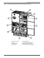
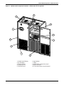
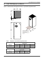
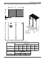
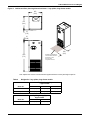
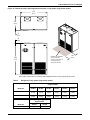
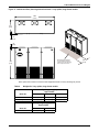
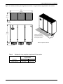
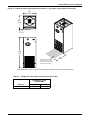
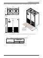
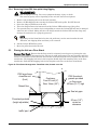
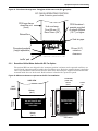
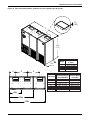
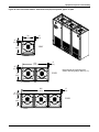
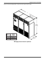
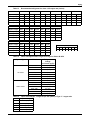
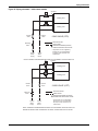
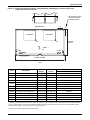
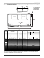
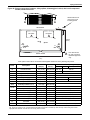
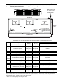
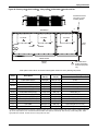
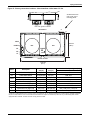
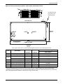
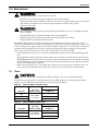
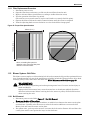
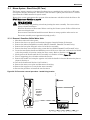
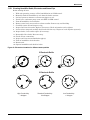
Liebert PEX Dimensions and Weights
Figure 14 Cabinet and floor planning dimensional data - 3 bay downflow, large frame EC fan models
2553
(100.5)
874
(34.4)
19
(0.75)
1970
(77.5)
Shaded area indicates a
recommended minimum
clearance for unit servicing
and component access
315
(12.4)
Note: Fan guard not shown
Table 9
Weights for 3 bay downflow, large frame EC fan models
Dry Weight - kg (lb),
Approximate
Model No.
3110GC
3140GC
Chilled Water EC
740 (1630)
760 (1670)
18
850
(33.5)
Liebert PEX Dimensions and Weights
Figure 15 Cabinet and floor planning dimensional data - 1 bay upflow, large frame EC fan models
853
(33.6)
874
(34.4)
19
(0.75)
1970
(77.5)
Shaded area indicates a
recommended minimum
clearance for unit servicing
and component access
850
(33.5)
Note: Upflow units must be connected to field supplied ductwork or factory discharge air plenum
Table 10
Weights for 1 bay upflow, large frame EC fan models
Dry Weight - kg (lb),
Approximate
Model No.
1020VC
1030VC
Chilled Water EC
270 (595)
270 (595)
19
Liebert PEX Dimensions and Weights
Figure 16 Cabinet and floor planning dimensional data - 2 bay upflow, large frame EC fan models
1704
(67.1)
874
(34.4)
19
(0.75)
1970
(77.5)
Shaded area indicates
a recommended
minimum clearance for
unit servicing and
component access
850
(33.5)
Note: Upflow units must be connected to field supplied ductwork or factory discharge air plenum
Table 11
Weights for 2 bay upflow, large frame EC fan models
Dry Weight - kg (lb),
Approximate
Model No.
2050VC
2070VC
Chilled Water EC
520 (1145)
520 (1145)
20
Liebert PEX Dimensions and Weights
Figure 17 Cabinet and floor planning dimensional data - 3 bay upflow, large frame EC fan models
2553
(100.5)
874
(34.4)
19
(0.75)
1970
(77.5)
Shaded area indicates a
recommended minimum
clearance for unit servicing
and component access
Note: Upflow units must be connected to field supplied ductwork or factory discharge air plenum
Table 12
Weights for 3 bay upflow, large frame EC fan models
Dry Weight - kg (lb),
Approximate
Model No.
3080VC
3110VC
Chilled Water EC
760 (1670)
760 (1670)
21
850
(33.5)
Equipment Inspection and Handling
5.0
EQUIPMENT INSPECTION AND HANDLING
Upon arrival of the unit and before unpacking it, verify that the labeled equipment matches the bill of
lading. Carefully inspect all items for damage, either visible or concealed. For initial access use a flatbladed screwdriver for panel removal. Damage should be immediately reported to the carrier and a
damage claim filed with a copy sent to Emerson or to your sales representative.
5.1
Packaging Material
All material used to package this unit is recyclable. Please save for future use or
dispose of the material appropriately.
R
SAFETY INFORMATION
! WARNING
Risk of top-heavy unit falling over. Can cause equipment damage, injury or death.
Read all of the following instructions before attempting to move the unit, lift it, remove
packaging or prepare the unit for installation.
! CAUTION
Risk of sharp edges, splinters and exposed fasteners. Can cause personal injury.
Only properly trained personnel wearing appropriate safety headgear, gloves, shoes and
glasses should attempt to move the unit, lift it, remove packaging or prepare the unit for
installation.
! CAUTION
Risk of overhead interference. Can cause unit and/or structure damage.
The unit may be too tall to fit through a doorway while on the pallet. Measure the unit and
doorway heights and refer to the installation plans to verify clearances prior to moving the
unit.
! CAUTION
Risk of damage from forklift. Can cause exterior and/or underside damage.
Keep tines of the forklift level and at a height suitable to fit below the pallet and/or unit.
! CAUTION
Risk of improper storage. Can cause unit damage.
Keep the unit upright, indoors and protected from dampness, freezing temperatures and
contact damage.
Figure 18 Equipment recommended for handling Liebert PEX
Forklift
Pallet
Jack
Piano Jacks
22
Spreader Bars
and Slings
Equipment Inspection and Handling
If possible, transport the Liebert PEX with a forklift or pallet jacks. If that is not possible, use a crane
with belts or cables, slings and spreader bars.
• If using a forklift or pallet jack, make sure that the forks (if adjustable) are spread to the widest
allowable distance that will fit under the pallet.
Ensure the fork length is suitable for the unit length.
• When moving the packaged Liebert PEX with a forklift, carefully lift the unit centrally and no
higher than 150mm (6") off the ground.
• If the unit must be lifted higher than 150mm (6"), great care must be exercised: Personnel who
are not directly involved in moving the unit must be kept 5m (20’) or farther from the lift point of
the unit..
5.2
Unpacking the Unit
Remove outer packaging when ready to install the unit.
• Identify the unit front by locating the styrene control cover.
• Remove the unit straps, packing tape and exterior stretch wrap packaging material from around
the unit, exposing the protective corner and vertical styrene packaging planks.
• Remove the timber frame packing, corner pieces and plastic cover from the unit top.
• Remove the balance of the stretch wrap packaging, styrene planks and kickplates from the unit.
Figure 19 Removing packaging
Timber frames
Top plastic
cover
Corner pieces
Control cover
(unit front)
Stretch wrap
Unit straps
Corner pieces
Pallet
Vertical planks
Kickplates
23
Equipment Inspection and Handling
5.2.1
Removing the Unit from the pallet With a Forklift
1. Align a forklift with either the front or rear side of the unit.
! WARNING
Risk of improper moving. Can cause equipment damage, injury or death.
The center of gravity varies depending on the unit size and selected options.
2. Insert the tines of the forklift completely under the base of the Liebert PEX.
! WARNING
Risk of improper moving. Can cause equipment damage, injury or death.
Ensure that the tines are level, not angled up or down.
The tines must be at a height that will allow proper clearance under the unit.
Ensure the tines extend beyond the opposite side of the unit.
3. Remove the lag bolts from each bracket holding the Liebert PEX to the pallet.
4. Lift the unit off the pallet—no more than 150mm (6")—and remove the pallet.
5.2.2
Moving the Unit to the Installation Location with Piano Jacks
1. With the Liebert PEX elevated, place two piano jacks into position—one at either end of the unit.
2. Lower the Liebert PEX to a height suitable for the piano jacks and place protective material
between the Liebert PEX and the piano jacks.
3. Secure the unit to the piano jacks and remove the forklift.
4. Use the piano jacks to move the Liebert PEX for installation.
5.2.3
Removing Piano Jacks
1. Lower the unit as much as the piano jacks will allow.
2. Undo all strapping holding the piano jacks to the unit.
3. Use a pry bar or similar device to lift one end of the unit just enough to allow removal of the piano
jack from that end.
4. Repeat Step 3 to remove the piano jack on the opposite end.
5. Remove all material that might have been used to protect the unit from the piano jacks and
strapping.
24
Equipment Inspection and Handling
5.2.4
Removing Liebert PEX from pallet Using Rigging
! WARNING
Risk of improper moving. Can cause equipment damage, injury or death.
The center of gravity varies depending on the unit size and selected options.
1.
2.
3.
4.
5.
Remove unit packaging and access the unit internals.
Remove all M8 shipping bolts securing the Liebert PEX to the pallet. Do NOT discard.
Space the slings equidistant on the unit.
Place the slings between the bottom rails of the Liebert PEX and the top of the pallet.
Use spreader bars or a similar device and padding to ensure the Liebert PEX will not be damaged
when the unit is lifted. Lifting will force the slings toward the Liebert PEX and the slings may
damage the unit unless it is properly protected.
NOTE
Depending on final installation location, the pallet may need to remain under the unit.
Therefore, the shipping bolts would not yet be removed.
6. Lift the Liebert PEX off the pallet.
7. Move the pallet from under the unit.
5.3
Placing the Unit on a Floor Stand
Emerson Floor Stand—Ensure that the floor stand is orientated correctly prior to placing the unit.
Level the floor stand by adjusting the feet. The use of waffle pad between the unit baseplate and floor
stand is recommended. Lower the unit onto the floor stand and align the unit baseplate with the floor
stand frame. The shipping bolt holes in the baseplate should align with matching holes in the floorstand frame. Refit the M8 shipping bolts in the baseplate and secure to the floor stand frame.
Figure 20 Floor Stand Arrangement - Downflow units, forward curve fan
PEX large frame
downflow unit
(front)
Overhang:
Front 50 mm (2")
Rear 18mm (3/4")
PEX floorstand gussets provided
on floors over
400mm (15.7") high
Raised floor
Seal air gaps
F.F.L.
Floorstand pedestal
(height adjustable)
50 mm (2.0")
minimum
clearance
’waffle’ pad
25
Equipment Inspection and Handling
Figure 21 Floor Stand Arrangement - Downflow chilled water units (EC fan option)
EC FAN IN OPERATING POSITION
(Note: Protective guard omitted)
PEX large frame
downflow unit
(front)
Unit overhang:
Front 50 mm (2")
Rear 18mm (3/4")
PEX floorstand gussets provided
on stands 400mm
(15.7") or higher
Raised floor
Seal air gaps
F.F.L.
Floorstand pedestal
(height adjustable)
50 mm (2.0")
minimum
clearance
’waffle’ pad
5.3.1
Downflow Chilled Water Units with EC Fan Option
The optional EC fans are shipped in the ’transport position’ and must not be operated until they are
secured in the ’operating position’ within the raised floor space. Each fan assembly frame is pivoted to
allow easy installation and removal from the front of the unit using the supplied installation handle
mounted inside the rear of the unit. Each fan frame is fitted with a protective guard.
Figure 22 Minimum clearance requirements for EC Fan Installation
PLAN VIEW
(1 BAY TYP.)
SIDE VIEW
600mm
(23.6")
DO NOT ROUTE ANY
SERVICES THROUGH
THIS AREA
DO NOT ROUTE ANY
SERVICES THROUGH
THIS AREA
780mm
(30.7")
UNIT FRONT
26
780mm (30.7")
874mm
(34.4")
874mm (34.4")
400mm
(13-3/4")
UNIT
FRONT
100mm
(4")
Equipment Inspection and Handling
EC Fan Installation Procedure
! WARNING
Risk of crushing and pinching action from pivoting fan motor assembly. Can cause serious
injury to hands and fingers.
Do not remove installation handle from unit. Return to storage position when not in use.
Fan motor assembly mass approximately 50kg (110lb.).
1. Locate the installation handle and M8 fixing screws in the rear of the unit, and attach the handle
to the fan plate in location A (refer Figure 23) using the same screws. Refer to Position 1 in
Figure 24.
2. Place downward pressure on the installation handle and remove the shipping plate that secures
the fan in the transport position. Retain the 6 fasteners.
3. Slowly raise the installation handle to lower the fan assembly into operating position 3.
4. Locate the filler plate, stowed with the installation handle, and fit between the fan deck and rear
panel using the fasteners removed in Step 2.
Figure 23 Installation handle fixing locations
B
EC Fan in ’shipping position’
viewed from unit front
A
Figure 24 Lowering EC fan motor into operating position
Shipping plate
1
2
Installation
handle
3
Filler plate
27
Equipment Inspection and Handling
Figure 25 Floorstand orientation & base plate fixing details
UNIT REAR
Note: M8 tapped fixing holes at
each end for securing unit base
UNIT FRONT
Note: Small cutouts at
front for pipe penetrations
28
Equipment Inspection and Handling
Figure 26 Upflow ducting configurations - forward curve fan systems, type D air path
3
2
1
2
1
3
2
1
1
Straight section of duct off unit to be min. 600mm
2
Recommended damper location
3
Alternate damper location
* Follow standard practices on all duct work.
29
Equipment Inspection and Handling
Figure 27 Duct connection details - forward curve fan systems, type D air path
23
(0.90)
A
L
L
B
1970
(77.5)
Width
L (mm)
Bays
874
(34.4)
C
D
E
Dimension
A
B
C
D
E
1-Bay
2-Bay
3-Bay
30
1
2
3
853 (33-1/2)
1704 (67)
2553 (100-1/2)
Air/Water/Glycol Chilled Water
PxxxxDA/W/G
PxxxxDC
404 (15-7/8)
258 (10-1/8)
437 (17-1/4)
830 (32-5/8)
900 (35-3/8)
476 (18-3/4)
385 (15-1/8)
420 (16-1/2)
815 (32-1/8)
885 (34-7/8)
Equipment Inspection and Handling
Figure 28 Duct connection details - backward curve(EC) fan systems, type V air path
67
(2.6)
720
(28.3)
58
(2.3)
726
(28.6)
1 BAY
67
(2.6)
1570
(61.8)
58
(2.3)
Note:Internal duct opening sizes
shown. Mounting flange 38mm (1.5").
726
(28.6)
58
(2.3)
2 BAY
67
(2.6)
2420
(95.3)
726
(28.6)
3 BAY
31
Equipment Inspection and Handling
Figure 29 Plenum discharge details - forward curve fans, type U and V air path
L
BAY
2520
(99.2)
Bays
1
2
3
Width
L (mm)
853 (33-1/2)
1704 (67)
2553 (100-1/2)
874
(34.4)
550 high plenum shown is optional
32
Electrical Connections
6.0
ELECTRICAL CONNECTIONS
Three-phase electrical service is required for all models. Electrical service must conform to national
and local electrical codes. Refer to equipment nameplate for unit full load amps. Refer to electrical
schematic when making connections. Refer to Figure 30 for electrical service entrances into unit.
A manual electrical isolation switch should be installed in accordance with local codes and distribution system. Consult local codes for external isolation requirements.
! WARNING
Risk of electric shock. Can cause injury or death.
Disconnect local and remote power supplies before working within.
Use voltmeter to make sure power is turned off before making any electrical connections.
Before proceeding with installation, read all instructions, verify that all the parts are included
and check the nameplate to be sure the voltage matches available utility power.
Follow all local codes.
! WARNING
Risk of improper wiring, piping, moving, lifting and handling. Can cause equipment damage,
injury or death.
Installation and service of this equipment should be done only by qualified personnel who
have been specially trained in the installation of air conditioning equipment.
! CAUTION
Risk of backward compressor rotation. Can cause equipment damage.
Three-phase power must be connected to the unit line voltage terminals in the proper
sequence so that scroll compressors rotate in the proper direction.
! CAUTION
Risk of improper electrical supply connection. Can cause equipment damage.
! CAUTION
Risk of overheated terminals. Can cause wiring and component damage.
Use copper wiring only. Make sure that all connections are tight.
33
Electrical Connections
Figure 30 Electrical panel general arrangement
Main Input Isolation
Switch, Neutral &
Earth Terminal
Opt. Ground Current
Detector (GCD) optional
Smoke Detector
Control (SDC)
optional
3, 4, 5
Temp Hum Sensor
(TH/HU) rear of elec panel
Air Sail Switch (AS)
Circuit Breakers
Smoke Detector
(SD) optional
Fuse Board
iCOM Board
High Temperature Stat
(HTS) optional
Filter Clog Switch (FC)
IntelliSlot
Power Supply
Field Terminals
Field and
Communication
Cables
2
15
13
41 42 43 44
11/19
18
58 59 84 85
Transformer Terminals
Transformer (T6)
Contactors /
Transformer (T1)
Overloads
Electrode Humidifier
Isolation Board (HIB)
IE humidifier units only
14
82 83 88 89
16
9
17
12
1
Power Supply/
Electrical Service
(others)
8
75 76 94 95 96 97 91 92 93 80 81 77 78
6
7
37C 38C 37B 38B 37 38 24
10
50 51 55 56 70 71 70A 71A
Refer to 6.1 - Electrical Field Connection Descriptions
for keys to numbered items.
Figure 31 Field connection terminals
! CAUTION
Field wiring to terminals 24VAC MAXIMUM VOLTAGE CONNECTION ONLY
34
Electrical Connections
6.1
Electrical Field Connection Descriptions
Standard Electrical Connections
1. High voltage entrance— 35mm (1-3/8") diameter hole and 44mm (1-3/4") knockout located in
bottom of box.
2. Low voltage entrance— 51mm (2") diameter hole located in bottom of box.
3. Three-phase electrical service—Input isolator. Three-phase service not by Liebert.
4. Earth ground—Terminal for field-supplied earth grounding wire.
5. Neutral— Terminal for field-supplied neutral wire.
6. Remote unit shutdown—Replace existing jumper between terminals 37 and 38 with field-supplied
normally closed switch having a minimum 75VA, 24VAC rating. Use field-supplied Class 1
wiring.
7. Customer alarm inputs—Terminals for field-supplied, normally open contacts, having a
minimum 75VA, 24VAC rating, between terminals 24 and 50, 51, 55, 56. Use field-supplied
Class 1 wiring. Terminal availability varies by unit options.
8. SiteScan—Terminals 77(-) and 78(+) for a two-wire, twisted pair, communication cable to optional
SiteScan.
9. Common alarm—On any alarm, normally open dry contact is closed across terminals 75 and 76
for remote indication. 1A, 24VAC max load. Use Class 1 field-supplied wiring.
10. Heat rejection interlock—On a call for compressor operation, normally open dry contacts are
closed across terminals 70 and 71 (compressor 1) and 70A and 71A (compressor 2) to heat
rejection equipment. 1A, 24VAC max load. Use Class 1 field-supplied wiring.
11. Water under floor sensor (LWD)—Field connections for factory supplied sensor and lead. Up to 5
sensors can be connected in series up to a maximum of 20m (65ft).
Optional Electrical Connections
12. Smoke sensor alarm—Factory wired dry contacts from smoke sensor are 91-common, 92-NO and
93-NC. Supervised contacts, 80 and 81, open on sensor trouble indication. This smoke sensor is
not intended to function as, or replace, any room smoke detection system that may be required by
local or national codes. 1A, 24VAC max load. Use Class 1 field-supplied wiring.
13. Reheat and humidifier lockout—Remote 24VAC required at terminals 82 and 83 for lockout of
reheat and humidifier.
14. Condensate alarm (with condensate pump option)—On pump high water indication, normally
open, dry contact is closed across terminals 88 and 89 for remote indication. 1A, 24VAC max load.
Use Class 1 field-supplied wiring.
15. Analog inputs—Terminals for up to two factory optional analog inputs. Device 1 wires to 41(-) and
42(+). Device 2 wires to 43(-) and 44(+).
Optional Low Voltage Terminal Package Connections
16. Remote unit shutdown - Two additional contact pairs available for unit shutdown (labeled as 37B
and 38B, 37C and 38C). Replace jumpers with field-supplied, normally closed switch having a
minimum 75VA, 24VAC rating. Use Class 1 field-supplied wiring.
17. Common alarm—On any alarm, two additional normally open dry contacts are closed across
terminals 94 and 95 and 96 and 97 for remote indication. 3A, 24VAC max load. Use Class 1
field-supplied wiring.
18. Main fan auxiliary switch—On closure of main fan contactor, normally open dry contact is closed
across terminals 84 and 85 for remote indication. 1A, 24VAC max load. Use Class 1 field-supplied
wiring.
19. Liqui-tect shutdown and dry contact—On Liqui-tect activation all fans shutdown and a normally
open dry contact is closed across terminals 58 and 59 for remote indication. Liqui-tect sensor
ordered separately. 1A, 24VAC max load. Use Class 1 field-supplied wiring. Cannot be used in
conjunction with LWD factory supplied water under floor sensor.
NOTE
Refer to specification sheet for total unit full load amps, wire size amps and maximum
overcurrent protective device size.
35
Electrical Connections
6.1.1
Water Under Floor Sensor (LWD)
Each Liebert PEX unit is shipped from the factory with a water under floor sensor, 3.7m (12ft) lead
and termination resistor for field connection. A maximum of 5 sensors may be connected in series.
Regardless of the quantity, a single termination resistor (value=24K ohm) must be fitted at the furthest end of the line.
Figure 32 Water Under Floor Sensor (LWD) wiring
Field connection
terminals in
electrical panel
58
59
Sensor 1
Sensor 2
Sensor 3
Sensor 4
Sensor 5
Termination
resistor
24K ohm
Max. 20 metres
6.1.2
Remote Air Cooled Condenser Power Kit Option
Air cooled Liebert PEX units can be supplied with an optional factory fitted power kit for remote electrical service to the outdoor air cooled condenser. A 16amp rated single pole circuit breaker and contactor is provided for each refrigeration circuit.
! CAUTION
Do not exceed the electrical rating for this circuit. Consult the factory should this service be
insufficient for condenser power requirements. Unit FLA includes 16amp allowance when
ordered as a factory option.
6.1.3
iCOM Network Cabling
Up to 2 off CAT5e cables may be required to connect each PEX iCOM unit to an external network
switch. These should be routed up the left hand side of the unit along with other low voltage field and
communication cables. Keep away from any power cables. Refer to Figure 30 - Electrical panel general arrangement.
Refer to 051536 iCOM User manual for PEX Applications for details on networking cable requirements.
6.1.4
IntelliSlot 485 and WEB/SNMP Cards
These optional cards require twisted pair shielded communication and CAT5e cables which should be
routed up the left hand side of the unit along with other low voltage field and communication cables.
Keep away from power cables. Refer to Figure 30 - Electrical panel general arrangement.
Refer to the IntelliSlot 485 and WEB/SNMP card technical documents for further information.
36
Piping
7.0
PIPING
All fluid and refrigeration connections to the unit, with the exception of the humidifier supply and
condensate drain, are sweat copper. Factory-installed piping brackets must not be removed. Fieldinstalled piping must be installed in accordance with local codes and must be properly assembled,
supported, isolated and insulated. Avoid piping runs through noise-sensitive areas, such as office
walls and conference rooms.
Refer to specific text and detailed diagrams in this manual for other unit-specific piping requirements.
All piping below the elevated floor must be located so that it offers the least resistance to air flow.
Careful planning of the piping layout under the raised floor is required to prevent the air flow from
being blocked. When installing piping on the subfloor, it is recommended that the pipes be mounted in
a horizontal plane rather than stacked one above the other. Whenever possible, the pipes should be
run parallel to the air flow.
7.1
Fluid Connections
! CAUTION
Risk of leaking water. Can cause equipment and building damage.
This unit requires a water drain connection and an external water supply to operate.
Improper installation, application and service practice can result in water leakage from the
unit. Water leakage can result in severe property damage and loss of critical data center
equipment.
Do not locate unit directly above any equipment that could sustain water damage.
Emerson recommends installing leak detection equipment for unit and supply lines.
7.1.1
Condensate Piping—Field-Installed
•
•
•
•
•
Do not reduce drain lines
Do not expose drain line to freezing temperatures
Drain line may contain boiling water. Use copper or other suitable material
Drain line must comply with local building codes
Emerson recommends installing under-floor leak detection equipment
Gravity Drain - Infrared Humidifier units
• 3/4" BSPM drain connection is provided on units without optional factory-installed condensate
pump
• Pitch drain line toward drain a minimum of 10mm per metre (1/8" per 1 foot) of length
• Drain is trapped internally. DO NOT trap external to equipment
• Drain line must be sized for 7.6 l/m (2 gpm) flow and suitable for boiling water
Gravity Drain - Immersed Electrode Humidifier units
• 25mm (1") O.D.drain connection is provided. The install pack includes a length of hose to extend
through the unit base
• Pitch drain line toward drain a minimum of 10mm per metre (1/8" per 1 foot) of length
• Drain MUST BE trapped externally
• Drain line must be sized for 7.6 l/m (2 gpm) flow and suitable for boiling water
Condensate Pump
• 1/2" copper sweat connection is provided on units with optional condensate pump (NB: factory
installed in Infrared humidifier units. Loose supplied for external installation in Immersed Electrode humidifier units
• Condensate pump (50Hz) is rated for approx. 1625 l/h at 3.2m (430 gph at 10 feet) total head
• Size piping based on available condensate head
37
Piping
7.1.2
Humidifier Supply Water
Infrared Humidifier
• 1/2" BSPM supply connection; maximum water pressure is 1034kPa (150 psi)
• Size humidifier supply line for 3.8 l/m (1 gpm), with a minimum water pressure of 140kPa (20 psi)
• Do not supply de-ionized water to the humidifier
Immersed Electrode Humidifier
• 1/2" BSPF supply connection; maximum water pressure is 700kPa (100psi)
• Size humidifier supply line for 3.8 l/m (1 gpm), with a minimum water pressure of 140kPa (20 psi)
• Do not supply de-ionized water to the humidifier
7.1.3
Requirements of Systems Using Water or Glycol
These guidelines apply to the field leak checking and fluid requirements for field piping systems, including Liebert chilled water, condenser (water or glycol) and drycooler circuits.General Guidelines
• Equipment damage and personal injury can result from improper piping installation, leak checking, fluid chemistry and fluid maintenance.
• Follow local piping codes and safety codes.
• Qualified personnel must install and inspect system piping.
• Contact a local water consultant regarding water quality, corrosion protection and freeze protection requirements.
• Install manual shutoff valves at the supply and return line to each indoor unit and drycooler to
permit routine service and emergency isolation of the unit.
! CAUTION
Risk of frozen fluids. Can cause equipment damage and building damage.
Freezing system fluids can rupture piping. Complete system drain-down cannot be ensured.
When the field piping or unit may be exposed to freezing temperatures, charge the system
with the proper percentage of glycol and water for the coldest design ambient.
Automotive antifreeze is unacceptable and must NOT be used in any glycol fluid system.
! CAUTION
Risk of corrosion. Can cause equipment damage.
Read and follow individual unit installation instructions for precautions regarding fluid
system design, material selection and use of field-provided devices. Liebert systems contain
stainless steel and copper alloys that require appropriate corrosion protection.
Contact a local water consultant regarding water quality, corrosion and freeze protection
requirements.
Water chemistry varies greatly by location, as do the required additives, called inhibitors,
that reduce the corrosive effect of the fluids on the piping systems and components. The
chemistry of the water used must be considered, because water from some sources may
contain corrosive elements that reduce the effectiveness of the inhibited formulation.
Preferably, surface waters that are classified as soft and are low in chloride and sulfate ion
content should be employed. Proper inhibitor maintenance must be performed in order to
prevent corrosion of the system. Consult glycol manufacturer for testing and maintenance of
inhibitors.
Commercial ethylene glycol (Union Carbide Ucartherm, Dow Chemical Dowtherm SR-1 and
Texaco E.G. Heat Transfer Fluid 100), when pure, is generally less corrosive to the common
metals of construction than water itself. It will, however, assume the corrosivity of the water from
which it is prepared and may become increasingly corrosive with use if not properly inhibited.
! CAUTION
Risk of oxide layer formation. Can cause equipment damage.
Idle fluid allows the collection of sediment that prevents the formation of a protective oxide
layer on the inside of tubes. Keep unit switched ON and system pump operating.
•
38
Piping
Leak Checking of Unit and Field Piping
Liebert PEX unit fluid systems are factory-checked for leaks and may be shipped with a nitrogen
holding charge. Liebert unit fluid circuits should be checked for leaks at installation as described
below.
NOTE
During leak checking of field-installed piping, Liebert recommends that the unit be isolated
using field-installed shutoff valves. When the Liebert units are included in a leak test, use of
fluid for pressure testing is recommended. When pressurized gas is used for leak testing the
Liebert unit, the maximum recommended pressure is 2 bar (30 psig) and tightness of the unit
should be verified by pressure decay over time, (<2 psig/hour [0.3 bars/hour]) or sensing a
tracer gas with suitable instrumentation. Dry seals in fluid valves and pumps may not hold a
high gas pressure.
7.2
Refrigeration Piping
! WARNING
Risk of explosive discharge from high-pressure refrigerant. Can cause injury or death.
This unit contains fluids and/or gases under high pressure.
Relieve pressure before working with piping. Recover refrigerant as per local codes.
Both high pressure (HP) and low pressure (LP) switches do NOT have a schrader valve core
fitted. Lower system pressures to atmosphere BEFORE removing either switch.
! CAUTION
Risk of oil contamination with water. Can cause equipment damage.
All Liebert PEX Systems require the use of POE (polyolester) oil. See 11.9.1 - Compressor Oil
for requirements. POE oil absorbs water at a much faster rate when exposed to air than
previously used oils. Because water is the enemy of a reliable refrigeration system, extreme
care must be used when opening systems during installation or service. If water is absorbed
into the POE oil, it will not be easily removed and will not be removed through the normal
evacuation process. If the oil is too wet, it may require an oil change. POE oils also have a
property that makes them act as a solvent in a refrigeration system. Maintaining system
cleanliness is extremely important because the oil will tend to bring any foreign matter back
to the compressor.
NOTE
The Liebert PEX indoor cooling unit has a factory-installed high pressure safety switch in the
high side refrigerant circuit.
7.2.1
Piping Guidelines—Air-Cooled Units
• Indoor unit ships with a nitrogen holding charge; do not vent the evaporator until all refrigerant
piping is in place, ready for connection to the unit and condenser
• Ensure unit field connection isolation valves are wrapped when brazing
• Use copper piping with high temperature brazed joints
• Isolate piping from building using vibration-isolating supports
• Refer to Table 13 for piping sizes
• Refer to condenser installation manual for charging information
• Install traps on hot gas (discharge) lines at the base of vertical risers and every 7.5m (25 feet) of
vertical rise.
• Consult factory if condenser is installed more than 5m (16 feet) below the evaporator
• Consult factory if piping run exceeds 60m (200 feet) equivalent length
• Keep piping clean and dry
• Avoid piping runs through noise-sensitive areas
• Do not run piping directly in front of airstream
• Refrigerant oil – do not mix oil types (see 11.9.1 - Compressor Oil)
Refer to ASHRAE Refrigeration Handbook for general good-practice refrigeration piping.
39
Piping
Table 13
Recommended refrigerant line sizes - OD copper mm (inches)
1020
Model
Equiv. Length
Gas
1025
Liquid
Gas
1030
Liquid
Gas
1035
Liquid
Gas
2045
Liquid
Gas
2055
Liquid
Gas
Liquid
15m (50ft)
22
13
22
16
28
16
28
16
28
16
28
16
30m (100ft)
22
16
22
16
28
16
28
19
28
22
28
22
45m (150ft)
22
16
28
16
28
22
28
22
35
22
35
22
60m (200ft)
28
16
28
19
28
22
28
22
35
22
35
22
2040
Model
Equiv. Length
Gas
2050
Liquid
Gas
2060
Liquid
Gas
2070
Liquid
Gas
Liquid
15m (50ft)
22
13
22
16
22
16
22
16
30m (100ft)
22
16
22
16
22
16
22
19
45m (150ft)
22
16
28
16
28
19
28
22
60m (200ft)
28
16
28
19
28
22
28
22
3080
Model
3090
3100
Equiv. Length
Gas
Liquid
Gas
Liquid
Gas
Liquid
15m (50ft)
28
16
28
16
28
16
30m (100ft)
28
22
28
22
28
22
45m (150ft)
28
22
35
22
35
22
60m (200ft)
35
22
35
22
35
22
Table 14
Air Cooled
Model
Refrigerant
Charge
per Circuit, kg (lb)
1020, 1025, 1030
2.3 (5.1)
1035
3.1 (6.8)
2045, 2055
4.9 (10.8)
2040, 2050, 2060
2.4 (5.3)
2070
3.2 (7.0)
3080, 3090
3.7 (8.1)
3100
5.0 (11.0)
1020
2.5 (5.5)
1025, 1030, 1035
2.75 (6.1)
2045, 2055
4.0 (8.8)
2040
2.5 (5.5)
2050, 2060
2.75 (6.1)
2070
4 (8.8)
3080, 3090, 3100
4 (8.8)
Water Cooled
O.D.
13
16
19
22
in.
1/2
5/8
3/4
7/8 1-1/8 1-3/8
28
Indoor unit approximate refrigerant charge for R-22 or R-407C
System Type
Table 15
Metric/Imperial Equivalents
mm
Liquid Line charges - refrigerant per 30m (100 ft) of Type “L” copper tube
Liquid Line, kg (lb)
1/2"
3.3 (7.3)
5/8"
5.3 (11.7)
3/4"
7.8 (17.2)
7/8"
11.1 (24.4)
1-1/8"
18.9 (41.6)
40
35
Piping
Table 16
Outdoor condenser approximate refrigerant charge kg (lb) per circuit
Model
Charge
kg (lb)
LS20
1.1 (2.4)
LS25
1.9 (4.2)
LS40
1.9 (4.2)
LS50
2.9 (6.4)
LS60
2.8 (6.2)
LS70
4.2 (9.2)
LS80
4.0 (8.8)
LS100
6.0 (13.2)
System Charge
Refer to Tables 14, 15 and 16 to estimate the total refrigerant charge required per circuit.
TOTAL CHARGE (per circuit) = indoor unit + liquid line + outdoor condenser
Additional Oil Requirements (Air Cooled Units only)
Whenever the TOTAL CHARGE per circuit exceeds the Base Charge Limit as listed in Table 17, additional oil (refer 11.9.1 - Compressor Oil) must be added to the system according to the following:
Oil add (ml) = [Total Charge - Base Charge Limit ] (kg) x 25
Oil add (oz.) = [Total Charge - Base Charge Limit] (lb.) x 0.35
The Base Charge Limit is defined as the total charge of refrigerant in the circuit that can be supported by the oil volume of the compressor before additional oil is required.
The amount of oil required within a circuit is more dependant on the refrigerant charge and compressor’s oil pumping rate than the physical length of piping to be wetted.
Table 17
Base Charge Limit for Air Cooled Units
System Type
Air Cooled
7.2.2
Model
Base Charge
Limit
per Circuit, kg (lb)
1020, 1025
7.7 (17.0)
1030, 1035
14.2 (31.2)
2045, 2055
14.2 (31.2)
2040, 2050
7.7 (17.0)
2060, 2070
14.2 (31.2)
3080, 3090, 3100
14.2 (31.2)
Piping Guidelines - Chilled Water units
• Units ship with a nitrogen holding charge; vent the circuits via the service/schrader access (bleed)
valves on the cooling coil header pipes
• Use copper piping with high temperature brazed joints
• Insulate supply and return pipes/valves to prevent condensation
• Do not run piping directly in front of airstream
• Downflow EC Fan units - do not route piping or other services in ’no-go’ regions - refer Figure 22 Minimum clearance requirements for EC Fan Installation
41
Piping
7.3
Dehydration/Leak Test and Charging Procedures for R-407C and R-22
7.3.1
Air Cooled Condenser with Electronic Fan Speed Head Pressure Control System
The Fan Speed Control system uses a pressure activated electronic fan speed control system to ensure
operation at ambient temperatures as low as -5°C (23°F). Refer to the Air Cooled Condenser technical
data manual for further information.
Fan Speed Control Piping
A copper discharge line and liquid line must be field-installed between the indoor unit and the outdoor condenser for each refrigeration circuit. See Figure 33 for details.
Electrical Interconnection
The remote air cooled condenser is factory wired and requires a single phase power supply (230-1-50)
to operate. The power supply for the condenser can be provided either from the indoor PEX unit (via
optional Remote Air Cooled Condenser Power Kit) or from a separate source. A 24VAC interlock connection is available from terminals 70-71 (70A-71A) in the PEX unit electrical panel. Refer Figure 31 Field connection terminals
Fan Speed Control Leak Check and Evacuation Procedure
Proper leak check and evacuation can be accomplished only with all system solenoid and isolation
valves open and check valves accounted for.
1. If unit power is available, open the unit liquid line solenoid valves using the evacuation function
for Compressor #1 and Compressor #2 in the diagnostic section of the iCOM control (refer to the
iCOM user manual, 051536). If unit power is not available, a field-supplied 24VAC / 75VA power
source must be directly connected to each of the unit solenoid valves.
2. Connect refrigerant gauges to the suction and discharge line Schrader access valves on both
compressors.
3. For each circuit, open the isolation valves and place a 150 PSIG (1034 kPa) dry nitrogen charge.
Check system for leaks using an acceptable leak test method.
NOTE
The use of fluorocarbon substances as a trace gas for leak testing is not permitted in many
countries. Check local refrigerant handling codes of practice before use.
4. After completion of leak testing, release the test pressure (per local code) and pull an initial deep
vacuum on the system with a suitable pump.
5. After four hours, check the pressure readings and, if they have not changed, break vacuum with
dry nitrogen. Pull a second (R-407C and R-22) and third (R407C only) vacuum to 250 microns or
less. Recheck the pressure after two hours. After completing this step, proceed to Fan Speed
Charging.
42
Piping
Fan Speed Charging
1. Check unit nameplate for refrigerant type to be used. Unit control configurations differ depending
on refrigerant type.
2. Refrigerant charging requires unit operation. Refer to 9.0 - Checklist for Completed Installation.
3. Calculate the amount of charge for the system. Refer to the unit, condenser and refrigerant line
charge data in Tables 14, 15 and 16.
4. Weigh in as much of the system charge as possible before starting the unit.
! CAUTION
Risk of improper refrigerant charging. Can cause equipment damage.
Refrigerant R407C is a blend of three components and must be introduced and charged from
the cylinder only as a liquid.
When adding liquid refrigerant to an operating system, it may be necessary to add the
refrigerant through the compressor suction line access valve. Care must be exercised to avoid
damage to the compressor. Emerson recommends connecting a sight glass between the
charging hose and the compressor suction line accesse valve. This will permit adjustment of
the cylinder hand valve so that liquid can leave the cylinder while allowing vapor to enter the
compressor.
5. Turn on unit isolation switch. Operate the unit for 30 minutes using the charging function for
Compressor #1 and Compressor #2 in the diagnostic section of the iCOM control (see iCOM user
manual, 051536). The charging function operates the compressor at full capacity and energizes
the evaporator fan motor and the liquid line solenoid valve. The reheat and humidifier are
disabled. A minimum 140kPa (20psig) must be established and maintained for the compressor to
operate. The charging function can be reset as many times as required to complete unit charging.
6. Charge the unit until the liquid line sight glass becomes clear.
7. As head pressure builds, the fan speed controlled condenser fans begin rotating. The fan(s) will
run at full speed when sufficient head pressure is developed—fans start to rotate at 1400 kPa
(200 psig) and reach full speed at 1800 kPa (260 psig). On decreasing pressure, the fans will stop
at 1350 kPa (195 psig).
43
Piping Schematics
8.0
PIPING SCHEMATICS
Figure 33 Piping schematic - air cooled, scroll compressor models
Inverted trap on discharge & liquid lines
to extend above base of coil by a
minimum of 190mm (7-1/2")
(n/a for optional long line kit systems**)
Liquid Return
Check**
Valve
Condenser
Coil
Condenser
Coil
Condenser located
BELOW evaporator
Check **
Valve
Hot Gas
Discharge
Condenser located
ABOVE evaporator
* Traps every 7.5m
(25ft) of rise
LIEBERT PEX UNIT
(and associated piping)
LIQUID
Sensing Bulb
Access
Port
HP
LP
Rotalock
Connector
Rotalock
Connector
COMPRESSOR
Solenoid
Valve***
Evaporator
Coil
Dehum
Sol Valve
Access
Port
SUCTION
External
Equaliser
Isolation
Valve
DISCHARGE
Access
Port
Expansion
Valve
Solenoid
Valve**
Hot Gas
Discharge
Liquid Return
Sight Filter Drier
Glass w/rotalock
connections
Isolation
Valve
(Optional Long
Line kit)
NOTE: SINGLE REFRIGERATION CIRCUIT SHOWN FOR CLARITY. DEHUM SOLENOID VALVE IN CIRCUIT 1 ONLY.
* Components are not supplied
by Emerson but are
recommended for proper circuit
operation and maintenance
FACTORY PIPING
FIELD PIPING
OPTIONAL FACTORY PIPING
SERVICE / SCHRADER (ACCESS) CONNECTION NO VALVE CORE
SERVICE / SCHRADER (ACCESS) CONNECTION WITH VALVE CORE
** Field installed check valves shipped
loose with optional long line kit
*** Single compressor models only
NOTE: SCHEMATIC REPRESENTATION SHOWN. THIS SCHEMATIC DOES NOT IMPLY OR DEFINE ELEVATIONS AND
COMPONENT LOCATION, UNLESS SPECIFICALLY NOTED.
44
REV 02/08
REV 0
Piping Schematics
Figure 34 Piping schematic - water/glycol, scroll compressor models
WATER SYSTEM
GLYCOL
PUMPS
Check Valves*
(on Dual Pump
Systems only)
Pressure
Port*
DRYCOOLER
(Glycol)
COOLING TOWER
AND PUMP
SYSTEM
BY OTHERS
Optional Dual Pump System shown
EXPANSION
TANK**
GLYCOL SYSTEM
Aquastat
Sensing
Bulbs
Hose
Bib*
Gate Valves*
Air Vents
(typical)***
Shut-Off Valve*
Pressure Port*
Flow Switch
Supplied with Dual
Pump Systems
Flow-Regulating
Valve*
Shut-Off Valve*
RETURN SUPPLY
RETURN
LIEBERT PEX UNIT
(and associated piping)
RETURN
LIQUID
Sensing Bulb
Access
Port
Dehum
Sol Valve
Access
Port
HP
LP
Rotalock
Connector
Solenoid
Valve##
COMPRESSOR
Check Valve
External
Equaliser
#
Hose
Bib*
Sight
Glass
Shut-Off
Valve*
Hose
Bib*
Strainer
(mandatory 1 mm
or #20 mesh)
2-Way
Regulating
Valve
Rotalock
Connector
RETURN
DISCHARGE
Access
Port
Expansion Solenoid
Valve
Valve#
Shut-Off
Valve*
SUCTION
Rotalock
Connector
SUPPLY
Balancing Valve*
Optional
3-WayRegulating
Valve
Evaporator
Coil
SUPPLY
By-Pass Valve
Brazed Plate
Condenser
Filter Drier
w/rotalock
connections
#
SUPPLY
Sensor
NOTE: SINGLE REFRIGERATION CIRCUIT SHOWN FOR CLARITY. DEHUM SOLENOID VALVE IN CIRCUIT 1 ONLY.
* Components are not supplied
by Emerson but are
recommended for proper circuit
operation and maintenance
FACTORY PIPING
FIELD PIPING
OPTIONAL FACTORY PIPING
SERVICE / SCHRADER (ACCESS) CONNECTION NO VALVE CORE
SERVICE / SCHRADER (ACCESS) CONNECTION WITH VALVE CORE
## single compressor models only
** Field installed at highest point in
system on return line to pumps
*** Locate at tops of all risers
and any intermediate system
high points
NOTE: SCHEMATIC REPRESENTATION SHOWN. THIS SCHEMATIC DOES NOT IMPLY OR DEFINE ELEVATIONS AND
COMPONENT LOCATION, UNLESS SPECIFICALLY NOTED.
45
# 2045, 2055, 3090, 3100 models only
REV 02/08
REV 0
Piping Schematics
Figure 35 Piping schematic - chilled water models
Air Bleed
M
A
B
Cooling Coil
M
A
B
Cooling Coil
Isolation
Valve*
Isolation
Valve*
2 WAY VALVE (STD)
FACTORY PIPING
Balancing
Valve*
FIELD PIPING
SERVICE/SCHRADER (ACCESS)
CONNECTION WITH VALVE CORE
Chilled
Water
Supply
* Components are not supplied by
Emerson but are recommended
for proper circuit operation and
maintenance
Chilled
Water
Return
NOTE: SCHEMATIC REPRESENTATION SHOWN.Air
THIS
SCHEMATIC DOES NOT IMPLY OR
Bleed
M LOCATION, UNLESS SPECIFCALLY NOTED.
DEFINE ELEVATIONS AND COMPONENT
C
A
Cooling Coil
B
M
C
A
Cooling Coil
B
Isolation
Valve*
Isolation
Valve*
3 WAY VALVE (OPT)
FACTORY PIPING
Balancing
Valve*
FIELD PIPING
SERVICE/SCHRADER (ACCESS)
CONNECTION WITH VALVE CORE
Chilled
Water
Supply
* Components are not supplied by
Emerson but are recommended
for proper circuit operation and
maintenance
Chilled
Water
Return
NOTE: SCHEMATIC REPRESENTATION SHOWN. THIS SCHEMATIC DOES NOT IMPLY OR
DEFINE ELEVATIONS AND COMPONENT LOCATION, UNLESS SPECIFCALLY NOTED.
46
Piping Schematics
Figure 36 Primary connection locations - 1 bay downflow, air/water/glycol cooled, single scroll
compressor, forward curve fan
A
All dimensions from
rear corner of unit
including panels
A
SECTION A-A
X
O
Y
Fan Outlet
F1
874 mm
(34.4")
HUM
CD
G1
WR1
L1
WS1
LV
E
FRONT OF UNIT
853 mm
(33.6")
Connection Size/Opening mm (in.)
X
Y
mm (in.)
mm (in.)
1020, 1025F
1030, 1035F
Hot Gas Circuit 1
103 (4)
714 (28-1/8)
5/8" I.D.
7/8" I.D.
L1
WS1
Liquid Line Circuit 1
Water/Glycol Supply Circ 1
173 (6-3/4)
173 (6-3/4)
764 (30-1/8)
764 (30-1/8)
WR1
Water/Glycol Return Circ 1
Condensate Drain (Infrared)*
103 (4)
737 (29)
714 (28-1/8)
532 (21)
w/Optional Pump
HUM-IR Humidifier water supply (Infrared)
CD-IE
Condensate Drain (Elect)*
737 (29)
637 (25)
737 (29)
532 (21)
485 (19-1/8)
532 (21)
HUM-IE
E
Humidifier water supply (Elect)
Electrical Conn. (High Volt)
637 (25)
60 (2-3/8)
485 (19-1/8)
760 (29-7/8)
1/2" BSP
34.9 (1-3/8); 44.4 (1-3/4) K.O.
LV
F1
Electrical Conn. (Low Volt)
Fan Outlet
807 (31-3/4)
247 (9-3/4)
780 (30-3/4)
358 (14-1/8)
25 (1)
410 x 310 (16-1/8 x 12-1/4)
Point
Description
G1
CD-IR
5/8" I.D.
1-1/8" I.D.
1-3/8" I.D.
1-1/4" O.D.
3/4" BSPM
1/2" comp.
1/2" BSP
25mm OD (1")
* Field-pitch condensate drain line a minimum of 10mm per metre (1/8" per ft.). Infrared humidifier units contain a factory installed condensate
trap. Do not trap external to unit. Immersed electrode humidifier units require an external trap. Drain line may contain boiling water. Select
appropriate drain materials. The drain line must comply with local codes.
47
Piping Schematics
Figure 37 Primary connection locations - 2 bay downflow, air/water/glycol cooled, single scroll
compressor, forward curve fan
A
All dimensions from
rear corner of unit
including panels
A
SECTION A-A
X
O
Y
Fan Outlet
Fan Outlet
F2
F1
874 mm
(34.4")
CD
HUM
LV
L1 G1
WS1
E
WR1
FRONT OF UNIT
1704 mm
(67")
Point
Description
X
mm (in.)
Y
mm (in.)
Connection Size/Opening mm (in.)
2045, 2055F**
G1
L1
WS1
WR1
Hot Gas Circuit 1
Liquid Line Circuit 1
Water/Glycol Supply Circ 1
Water/Glycol Return Circ 1
Condensate Drain (Infrared)*
169 (6-5/8)
239 (9-3/8)
1549 (61)
1479 (58-1/4)
869 (34-1/4)
775 (30-1/2)
775 (30-1/2)
775 (30-1/2)
775 (30-1/2)
632 (25)
7/8" I.D.
5/8" I.D.
1-1/4" I.D.
1-1/4" O.D.
3/4" BSPM
HUM-IR
CD-IE
HUM-IE
w/Optional Pump
Humidifier water supply (Infrared)
Condensate Drain (Elect)*
Humidifier water supply (Elect)
869 (34-1/4)
745 (29-1/4)
869 (34-1/4)
745 (29-1/4)
632 (25)
681 (26-3/4)
632 (25)
681 (26-3/4)
3/8" comp.
1/2" BSP
25mm OD (1")
1/2" BSP
E
LV
F1
F2
Electrical Conn. (High Volt)
Electrical Conn. (Low Volt)
Fan Outlet
Fan Outlet
60 (2-3/8)
1652 (65)
315 (12-3/8)
997 (39-1/4)
760 (29-7/8)
735 (28-7/8)
358 (14-1/8)
358 (14-1/8)
34.9 (1-3/8); 44.4 (1-3/4) K.O.
25 (1)
410 x 310 (16-1/8 x 12-1/4)
CD-IR
* Field-pitch condensate drain line a minimum of 10mm per metre (1/8" per ft.). Infrared humidifier units contain a factory installed condensate
trap. Do not trap external to unit. Immersed electrode humidifier units require an external trap. Drain line may contain boiling water. Select
appropriate drain materials. The drain line must comply with local codes.
** Water circuit includes regulating valve and bypass valve
48
Piping Schematics
Figure 38 Primary connection locations - 2 bay downflow air/water/glycol cooled, dual scroll compressor
models, forward curve fan
A
All dimensions from
rear corner of unit
including panels
A
SECTION A-A
X
O
Y
Fan Outlet
Fan Outlet
F2
F1
874 mm
(34.4")
CD
LV G2
WS2
HUM
L2
WR2
L1
WS1
G1
WR1 E
FRONT OF UNIT
1704 mm
(67")
X
Y
mm (in.)
mm (in.)
2040F
Hot Gas Circuit 1
169 (6-5/8)
775 (30-1/2)
5/8" I.D.
2060, 2070F
7/8" I.D.
G2
L1
Hot Gas Circuit 2
Liquid Line Circuit 1
1549 (61)
239 (9-3/8)
775 (30-1/2)
775 (30-1/2)
5/8" I.D.
7/8" I.D.
L2
WS1
Liquid Line Circuit 2
Water/Glycol Supply Circ 1
1479 (58-1/4)
239 (9-3/8)
775 (30-1/2)
775 (30-1/2)
WS2
WR1
Water/Glycol Supply Circ 2
Water/Glycol Return Circ 1
1549 (61)
169 (6-5/8)
775 (30-1/2)
775 (30-1/2)
WR2
Water/Glycol Return Circ 2
Condensate Drain (Infrared)*
1479 (58-1/4)
869 (34-1/4)
775 (30-1/2)
632 (24-7/8)
HUM-IR
w/Optional Pump
Humidifier water supply (Infrared)
869 (34-1/4)
745 (29-3/8)
632 (24-7/8)
681 (26-3/4)
CD-IE
HUM-IE
Condensate Drain (Elect)*
Humidifier water supply (Elect)
869 (34-1/4)
745 (29-3/8)
632 (24-7/8)
681 (26-3/4)
E
LV
Electrical Conn. (High Volt)
Electrical Conn. (Low Volt)
60 (2-3/8)
1652 (65)
760 (29-7/8)
735 (28-7/8)
F1
F2
Fan Outlet
Fan Outlet
315 (12-3/8)
997 (39-1/4)
358 (14-1/8)
358 (14-1/8)
Point
Description
G1
CD-IR
Connection Size/Opening mm (in.)
2050F
5/8" I.D.
5/8" I.D.
1-1/8" I.D.
1-1/8" I.D.
1-3/8" I.D.
1-3/8" I.D.
1-1/4" O.D.
1-1/4" O.D.
3/4" BSPM
3/8" comp.
1/2" BSP
25mm OD (1")
1/2" BSP
34.9 (1-3/8); 44.4 (1-3/4) K.O.
25 (1)
410 x 310 (16-1/8 x 12-1/4)
* Field-pitch condensate drain line a minimum of 10mm per metre (1/8" per ft.). Infrared humidifier units contain a factory installed condensate
trap. Do not trap external to unit. Immersed electrode humidifier units require an external trap. Drain line may contain boiling water. Select
appropriate drain materials. The drain line must comply with local codes.
49
Piping Schematics
Figure 39 Primary connection locations - 3 bay downflow, air/water/glycol cooled, dual scroll compressor,
forward curve fan
All dimensions from
rear corner of unit
including panels
A
A
X
SECTION A-A
O
Y
Fan Outlet
Fan Outlet
Fan Outlet
F3
F2
F1
874 mm
(34.4")
CD
LV G2
WS2
HUM
L1
WS1
L2
WR2
G1
WR1
E
FRONT OF UNIT
2553 mm
(100.5")
X
Y
Point
Description
mm (in.)
mm (in.)
G1
G2
L1
Hot Gas Circuit 1
Hot Gas Circuit 2
Liquid Line Circuit 1
1019 (40-1/8)
2399 (94-1/2)
1089 (42-7/8)
775 (30-1/2)
775 (30-1/2)
775 (30-1/2)
L2
WS1
WS2
Liquid Line Circuit 2
Water/Glycol Supply Circ 1
Water/Glycol Supply Circ 2
2329 (91-3/4)
1089 (42-7/8)
2399 (94-1/2)
775 (30-1/2)
775 (30-1/2)
775 (30-1/2)
WR1
WR2
Water/Glycol Return Circ 1
Water/Glycol Return Circ 2
Condensate Drain (Infrared)*
1019 (40-1/8)
2329 (91-3/4)
1719 (67-5/8)
775 (30-1/2)
775 (30-1/2)
632 (24-7/8)
w/Optional Pump
1719 (67-5/8)
Humidifier water supply (Infrared) 1595 (62-3/4)
Condensate Drain (Elect)*
1719 (67-5/8)
632 (24-7/8)
681 (26-3/4)
632 (24-7/8)
CD-IR
HUM-IR
CD-IE
HUM-IE
E
Humidifier water supply (Elect)
Electrical Conn. (High Volt)
1595 (62-3/4)
910 (35-7/8)
681 (26-3/4)
760 (29-7/8)
LV
F1
F2
Electrical Conn. (Low Volt)
Fan Outlet
Fan Outlet
2502 (98-1/2)
247 (9-3/4)
1165 (45-7/8)
735 (28-7/8)
358 (14-1/8)
358 (14-1/8)
F3
Fan Outlet
1847 (72-3/4)
358 (14-1/8)
Connection Size/Opening mm (in.)
3080F
3090, 3100F**
7/8" I.D.
7/8" I.D.
5/8" I.D.
5/8" I.D.
1-3/8" I.D.
1-1/4" I.D.
1-3/8" I.D.
1-1/4" I.D.
1-1/4" O.D.
1-1/4" O.D.
3/4" BSPM
3/8" comp.
1/2" BSP
25mmOD (1")
1/2" BSP
34.9 (1-3/8); 44.4 (1-3/4) K.O.
25 (1)
410 x 310 (16-1/8 x 12-1/4)
* Field-pitch condensate drain line a minimum of 10mm per metre (1/8" per ft.). Infrared humidifier units contain a factory installed condensate
trap. Do not trap external to unit. Immersed electrode humidifier units require an external trap. Drain line may contain boiling water. Select
appropriate drain materials. The drain line must comply with local codes.
** Water circuit includes regulating valve and bypass valve
50
Piping Schematics
Figure 40 Primary connection locations - 1 bay upflow, air/water/glycol cooled, single scroll compressor
models, forward curve fan
A
A
SECTION A-A
X
All dimensions from
rear corner of unit
including panels
O
Y
Fan Outlet
1
F1
HUM
874 mm
(34.4")
CD
G1
WR1
L1
WS1
LV
E
1
FRONT OF UNIT
853 mm
(33.6")
Fan outlet shown
for duct connection
illustration purposes
only
Note: Upflow units must be connected to field supplied ductwork or factory discharge air plenum
Connection Size/Opening mm (in.)
X
Y
mm (in.)
mm (in.)
1020, 1025U
1030, 1035U
Hot Gas Circuit 1
107 (4-1/4)
656 (25-7/8)
5/8" I.D.
7/8" I.D.
Point
Description
G1
L1
Liquid Line Circuit 1
177 (7)
656 (25-7/8)
5/8" I.D.
WS1
Water/Glycol Supply Circ 1
177 (7)
656 (25-7/8)
WR1
Water/Glycol Return Circ 1
107 (4-1/4)
656 (25-7/8)
1-1/8" I.D.
1-3/8" I.D.
1-1/4" O.D.
Condensate Drain (Infrared)*
735 (28-7/8)
480 (18-7/8)
3/4" BSPM
w/Optional Pump
735 (28-7/8)
480 (18-7/8)
3/8" comp.
HUM-IR
CD-IE
Humidifier water supply (Infrared)
Condensate Drain (Elect)*
637 (25-1/8)
735 (28-7/8)
331 (13)
480 (18-7/8)
1/2" BSP
25mm OD (1")
HUM-IE
Humidifier water supply (Elect)
637 (25-1/8)
331 (13)
1/2" BSP
CD-IR
E
Electrical Conn. (High Volt)
60 (2-3/8)
760 (29-7/8)
34.9 (1-3/8); 44.4 (1-3/4) K.O.
LV
Electrical Conn. (Low Volt)
792 (31-1/8)
765 (30-1/8)
25 (1)
F1
Fan Outlet
185 (7-1/4)
311 (12-1/4)
404 x 258 (15-7/8 x 10-1/8)
* Field-pitch condensate drain line a minimum of 10mm per metre (1/8" per ft.). Infrared humidifier units contain a factory installed condensate
trap. Do not trap external to unit. Immersed electrode humidifier units require an external trap. Drain line may contain boiling water. Select
appropriate drain materials. The drain line must comply with local codes.
51
Piping Schematics
Figure 41 Primary connection locations - 2 bay upflow, air/water/glycol cooled, single scroll compressor
models, forward curve fan
A
All dimensions from
rear corner of unit
including panels
A
SECTION A-A
X
O
Y
Fan Outlet
1
Fan Outlet
1
F1
F2
874 mm
(34.4")
CD
HUM
WS1
L1 G1
WR1
LV
E
FRONT OF UNIT
1
1704 mm
(67")
Fan outlet shown
for duct connection
illustration purposes
only
Note: Upflow units must be connected to field supplied ductwork or factory discharge air plenum
Point
Description
X
Y
Connection Size/Opening mm (in.)
mm (in.)
mm (in.)
2045, 2055U**
G1
Hot Gas Circuit 1
114 (4-1/2)
665 (26-1/8)
7/8" I.D.
L1
WS1
Liquid Line Circuit 1
Water/Glycol Supply Circ 1
184 (7-1/4)
1543 (60-3/4)
665 (26-1/8)
665 (26-1/8)
5/8" I.D.
1-1/4" I.D.
WR1
Water/Glycol Return Circ 1
Condensate Drain (Infrared)*
1473 (58)
867 (34-1/8)
665 (26-1/8)
473 (18-5/8)
1-1/4" O.D.
3/4" BSPM
HUM-IR
w/Optional Pump
Humidifier water supply (Infrared)
867 (34-1/8)
712 (28)
473 (18-5/8)
512 (20-1/8)
3/8" comp.
1/2" BSP
CD-IE
HUM-IE
Condensate Drain (Elect)*
Humidifier water supply (Elect)
867 (34-1/8)
712 (28)
473 (18-5/8)
512 (20-1/8)
25mm OD (1")
1/2" BSP
E
LV
F1
Electrical Conn. (High Volt)
Electrical Conn. (Low Volt)
Fan Outlet
60 (2-3/8)
1642 (64-5/8)
235 (9-1/4)
760 (29-7/8)
765 (30-1/8)
311 (12-1/4)
34.9 (1-3/8); 44.4 (1-3/4) K.O.
25 (1)
404 x 258 (15-7/8 x 10-1/8)
F2
Fan Outlet
1065 (41-7/8)
311 (12-1/4)
404 x 258 (15-7/8 x 10-1/8)
CD-IR
* Field-pitch condensate drain line a minimum of 10mm per metre (1/8" per ft.). Infrared humidifier units contain a factory installed condensate
trap. Do not trap external to unit. Immersed electrode humidifier units require an external trap. Drain line may contain boiling water. Select
appropriate drain materials. The drain line must comply with local codes.
** Water circuit includes regulating valve and bypass valve
52
Piping Schematics
Figure 42 Primary connection locations - 2 bay upflow, air/water/glycol cooled, dual scroll compressor
models, forward curve fan
A
All dimensions from
rear corner of unit
including panels
A
SECTION A-A
X
O
Y
Fan Outlet
1
Fan Outlet
1
F1
F2
874 mm
(34.4")
CD
G2
WS2
LV
HUM
L2
WR2
L1
WS1
G1
WR1
E
1
FRONT OF UNIT
1704 mm
(67")
Fan outlet shown
for duct connection
illustration purposes
only
Note: Upflow units must be connected to field supplied ductwork or factory discharge air plenum
X
Y
Connection Size/Opening mm (in.)
Point
Description
mm (in.)
mm (in.)
2040U
G1
Hot Gas Circuit 1
114 (4-1/2)
665 (26-1/8)
5/8" I.D.
G2
L1
L2
WS1
WS2
Hot Gas Circuit 2
Liquid Line Circuit 1
Liquid Line Circuit 2
Water/Glycol Supply Circ 1
Water/Glycol Supply Circ 2
1543 (60-3/4)
184 (7-1/4)
1473 (58)
184 (7-1/4)
1543 (60-3/4)
665 (26-1/8)
665 (26-1/8)
665 (26-1/8)
665 (26-1/8)
665 (26-1/8)
5/8" I.D.
WR1
WR2
Water/Glycol Return Circ 1
Water/Glycol Return Circ 2
Condensate Drain (Infrared)*
w/Optional Pump
114 (4-1/2)
1473 (58)
867 (34-1/8)
867 (34-1/8)
665 (26-1/8)
665 (26-1/8)
473 (18-5/8)
473 (18-5/8)
Humidifier water supply (Infrared)
712 (28)
Condensate Drain (Elect)*
867 (34-1/8)
Humidifier water supply (Elect)
712 (28)
Electrical Conn. (High Volt)
60 (2-3/8)
Electrical Conn. (Low Volt)
1642 (64-5/8)
512 (20-1/8)
473 (18-5/8)
512 (20-1/8)
760 (29-7/8)
765 (30-1/8)
CD-IR
HUM-IR
CD-IE
HUM-IE
E
LV
F1
F2
Fan Outlet
Fan Outlet
235 (9-1/4)
1065 (41-7/8)
311 (12-1/4)
311 (12-1/4)
2050U
2060, 2070U
7/8" I.D.
7/8" I.D.
5/8" I.D.
5/8" I.D.
1-1/8" I.D.
1-3/8" I.D.
1-1/8" I.D.
1-3/8" I.D.
1-1/4" O.D.
1-1/4" O.D.
3/4" BSPM
3/8" comp.
1/2" BSP
25mm OD (1")
1/2" BSP
34.9 (1-3/8); 44.4 (1-3/4) K.O.
25 (1)
404 x 258 (15-7/8 x 10-1/8)
* Field-pitch condensate drain line a minimum of 10mm per metre (1/8" per ft.). Infrared humidifier units contain a factory installed condensate
trap. Do not trap external to unit. Immersed electrode humidifier units require an external trap. Drain line may contain boiling water. Select
appropriate drain materials. The drain line must comply with local codes.
53
Piping Schematics
Figure 43 Primary connection locations - 3 bay upflow, air/water/glycol cooled, dual scroll compressor
models, forward curve fan
All dimensions from
rear corner of unit
including panels
A
A
X
SECTION A-A
Fan Outlet
Fan Outlet
Fan Outlet
1
1
1
F3
F2
CD
Y
F1
874 mm
(34.4")
HUM
L2
WS2
LV
O
L1
WS1
G2
WR2
G1
WR1
E
1
Fan outlet shown
for duct connection
illustration purposes
only
FRONT OF UNIT
2553 mm
(100.5")
Note: Upflow units must be connected to field supplied ductwork or factory discharge air plenum
X
Y
mm (in.)
mm (in.)
Hot Gas Circuit 1
Hot Gas Circuit 2
964 (38)
2393 (94-1/4)
665 (26-1/8)
665 (26-1/8)
3090, 3100U**
7/8" I.D.
7/8" I.D.
Liquid Line Circuit 1
1034 (40-3/4)
665 (26-1/8)
5/8" I.D.
Point
Description
G1
G2
L1
Connection Size/Opening mm (in.)
3080U
5/8" I.D.
L2
Liquid Line Circuit 2
2323 (91-1/2)
665 (26-1/8)
WS1
Water/Glycol Supply Circ 1
1034 (40-3/4)
665 (26-1/8)
1-3/8" I.D.
WS2
Water/Glycol Supply Circ 2
2393 (94-1/4)
665 (26-1/8)
WR1
Water/Glycol Return Circ 1
964 (38)
665 (26-1/8)
1-3/8" I.D.
1-1/4" I.D.
1-1/4" O.D.
WR2
Water/Glycol Return Circ 2
2323 (91-1/2)
665 (26-1/8)
1-1/4" O.D.
Condensate Drain (Infrared)*
1717 (67-5/8)
473 (18-5/8)
3/4" BSPM
w/Optional Pump
1717 (67-5/8)
473 (18-5/8)
3/8" comp.
Humidifier water supply (Infrared) 1562 (61-1/2)
CD-IR
1-1/4" I.D.
512 (20-1/8)
1/2" BSP
CD-IE
HUM-IE
Condensate Drain (Elect)*
Humidifier water supply (Elect)
1717 (67-5/8)
1562 (61-1/2)
473 (18-5/8)
512 (20-1/8)
25mm OD (1")
E
Electrical Conn. (High Volt)
60 (2-3/8)
760 (29-7/8)
LV
Electrical Conn. (Low Volt)
2492 (98-1/8)
765 (30-1/8)
25 (1)
HUM-IR
1/2" BSP
34.9 (1-3/8); 44.4 (1-3/4) K.O.
F1
Fan Outlet
185 (7-1/4)
311 (12-1/4)
404 x 258 (15-7/8 x 10-1/8)
F2
Fan Outlet
1085 (42-3/4)
311 (12-1/4)
404 x 258 (15-7/8 x 10-1/8)
F3
Fan Outlet
1915 (75-3/8)
311 (12-1/4)
404 x 258 (15-7/8 x 10-1/8)
* Field-pitch condensate drain line a minimum of 10mm per metre (1/8" per ft.). Infrared humidifier units contain a factory installed condensate
trap. Do not trap external to unit. Immersed electrode humidifier units require an external trap. Drain line may contain boiling water. Select
appropriate drain materials. The drain line must comply with local codes.
** Water circuit includes regulating valve and bypass valve
54
Piping Schematics
Figure 44 Primary connection locations - 1 bay downflow, chilled water, forward curve fan
A
A
All dimensions from
rear corner of unit
including panels
SECTION A-A
X
O
Y
Fan Outlet
874 mm
(34.4")
F1
HUM
CD
CR
CS
LV
E
FRONT OF UNIT
853 mm
(33.6")
Point
Description
X
mm (in.)
Y
mm (in.)
Connection Size/Opening mm (in.)
1020, 1030, 1040FC
CS
CR
HUM
E
LV
Chilled Water Supply
Chilled Water Return
Condensate Drain*
w/Optional Pump
Humidifier water supply
Electrical Conn. (High Volt)
Electrical Conn. (Low Volt)
768 (30-1/4)
768 (30-1/4)
752 (29-1/2)
752 (29-1/2)
794 (31-1/4)
60 (2-1/4)
792 (31-1/4)
588 (23-1/4)
687 (27)
523 (20-1/2)
523 (20-1/2)
523 (20-1/2)
760 (29-7/8)
764 (30)
1-1/4" O.D.
1-1/4" O.D.
IR: 3/4" BSPM IE: 1"
3/8" comp.
1/2" BSP
34.9 (1-3/8); 44.4 (1-3/4) K.O.
25 (1)
F1
Fan Outlet
206 (8)
401 (15-3/4)
476 x 385 (18-3/4 x 15-1/4)
CD
* Field-pitch condensate drain line a minimum of 10mm per metre (1/8" per ft.). Infrared humidifier units contain a factory installed
condensate trap. Do not trap external to unit. Immersed electrode humidifier units require an external trap. Drain line may contain boiling
water. Select appropriate drain materials. The drain line must comply with local codes.
55
Piping Schematics
Figure 45 Primary connection locations - 2 bay downflow, chilled water, forward curve fan
All dimensions from
rear corner of unit
including panels
A
A
SECTION A-A
X
O
Y
Fan Outlet
Fan Outlet
CD-IR
F2
HUM-IR
874 mm
(34.4")
F1
CD-IE
CS
HUM-IE
CR
LV
E
FRONT OF UNIT
1704 mm
(67.1")
X
Y
Connection Size/Opening mm (in.)
mm (in.)
mm (in.)
2050, 2070, 2090FC
Chilled Water Supply
1618 (63-3/4)
588 (23-1/4)
1-5/8" O.D.
Chilled Water Return
1618 (63-3/4)
687 (27)
1-5/8" O.D.
Condensate Drain (Infrared)*
1602 (63)
523 (20-1/2)
3/4" BSPM
632 (25)
523 (20-1/2)
3/8" comp.
1/2" BSP
Point
Description
CS
CR
CD-IR
HUM-IR
w/Optional Pump
884 (34-3/4)
Humidifier water supply (Infrared) 1644 (64-3/4)
CD-IE
Condensate Drain (Elect)*
884 (34-3/4)
632 (25)
25mm OD (1")
HUM-IE
Humidifier water supply (Elect)
775 (30-1/2)
681 (26-3/4)
1/2" BSP
E
Electrical Conn. (High Volt)
60 (2-1/4)
760 (29-7/8)
34.9 (1-3/8); 44.4 (1-3/4) K.O.
LV
Electrical Conn. (Low Volt)
1642 (64-3/4)
764 (30)
25 (1)
F1
F2
Fan Outlet
Fan Outlet
217 (8-1/2)
1007 (39-3/4)
401 (15-3/4)
401 (15-3/4)
476 x 385 (18-3/4 x 15-1/4)
* Field-pitch condensate drain line a minimum of 10mm per metre (1/8" per ft.). Infrared humidifier units contain a factory installed condensate
trap. Do not trap external to unit. Immersed electrode humidifier units require an external trap. Drain line may contain boiling water. Select
appropriate drain materials. The drain line must comply with local codes.
56
Piping Schematics
Figure 46 Primary connection locations - 3 bay downflow, chilled water, forward curve fan
All dimensions from
rear corner of unit
including panels
A
A
X
SECTION A-A
O
Y
Fan Outlet
Fan Outlet
Fan Outlet
F3
F1
F2
HUM-IR
CS
874 mm
(34.4")
CD-IR
CD-IE
CR
HUM-IE
E
LV
FRONT OF UNIT
2553 mm
(100.5")
Y
Connection Size/Opening mm (in.)
mm (in.)
mm (in.)
3110, 3140FC
2468 (97-1/4)
588 (23-1/4)
2" O.D.
2468 (97-1/4)
794 (31-1/4)
687 (27)
523 (20-1/2)
2" O.D.
3/4" BSPM
794 (31-1/4)
523 (20-1/2)
3/8" comp.
Humidifier water supply (Infrared) 2494 (98-1/4)
Point
Description
CS
Chilled Water Supply
CR
Chilled Water Return
Condensate Drain (Infrared)*
w/Optional Pump
CD-IR
HUM-IR
X
523 (20-1/2)
1/2" BSP
CD-IE
HUM-IE
Condensate Drain (Elect)*
Humidifier water supply (Elect)
1734 (68-1/4)
1625 (64)
632 (25)
681 (26-3/4)
25mm OD (1")
1/2" BSP
E
Electrical Conn. (High Volt)
60 (2-1/4)
760 (29-7/8)
34.9 (1-3/8); 44.4 (1-3/4) K.O.
LV
Electrical Conn. (Low Volt)
2492 (98)
764 (30)
25 (1)
F1
F2
Fan Outlet
Fan Outlet
206 (8)
1067 (42)
401 (15-3/4)
401 (15-3/4)
476 x 385 (18-3/4 x 15-1/4)
F3
Fan Outlet
1857 (73)
401 (15-3/4)
476 x 385 (18-3/4 x 15-1/4)
* Field-pitch condensate drain line a minimum of 10mm per metre (1/8" per ft.). Infrared humidifier units contain a factory installed condensate
trap. Do not trap external to unit. Immersed electrode humidifier units require an external trap. Drain line may contain boiling water. Select
appropriate drain materials. The drain line must comply with local codes.
57
Piping Schematics
Figure 47 Primary connection locations - 1 bay upflow, chilled water, forward curve fan
All dimensions from
rear corner of unit
including panels
A
A
SECTION A-A
X
O
Y
Fan Outlet
1
HUM
CD
874 mm
(34.4")
F1
CR CS
1
E
LV
Fan outlet shown
for duct connection
illustration purposes
only
FRONT OF UNIT
853 mm
(33.6")
Note: Upflow units must be connected to field supplied ductwork or factory discharge air plenum
X
Y
Connection Size/Opening mm (in.)
mm (in.)
mm (in.)
1020, 1030UC/DC
Chilled Water Supply
690 (27-1/4)
600 (23-1/2)
1-1/4" O.D.
Chilled Water Return
Condensate Drain*
w/Optional Pump
780 (30-3/4)
794 (31-1/4)
794 (31-1/4)
600 (23-1/2)
537 (21-1/4)
537 (21-1/4)
1-1/4" O.D.
IR: 3/4" BSPM IE: 1"
3/8" comp.
HUM
E
LV
Humidifier water supply
Electrical Conn. (High Volt)
Electrical Conn. (Low Volt)
794 (31-1/4)
60 (2-1/4)
792 (31-1/4)
492 (19-1/4)
760 (29-7/8)
764 (30)
1/2" BSP
34.9 (1-3/8); 44.4 (1-3/4) K.O.
25 (1)
F1
Fan Outlet
195 (7-3/4)
456 (18)
476 x 385 (18-3/4 x 15-1/4)
Point
Description
CS
CR
CD
* Field-pitch condensate drain line a minimum of 10mm per metre (1/8" per ft.). Infrared humidifier units contain a factory installed
condensate trap. Do not trap external to unit. Immersed electrode humidifier units require an external trap. Drain line may contain boiling
water. Select appropriate drain materials. The drain line must comply with local codes.
58
Piping Schematics
Figure 48 Primary connection locations - 2 bay upflow, chilled water, forward curve fan
All dimensions from
rear corner of unit
including panels
A
A
X
SECTION A-A
O
Y
Fan Outlet
Fan Outlet
1
1
F2
HUM-IR
CD-IR
F1
874 mm
(34.4")
HUM-IE
CD-IE
CR CS
E
LV
FRONT OF UNIT
1
1704 mm
(67.1")
Fan outlet shown
for duct connection
illustration purposes
only
Note: Upflow units must be connected to field supplied ductwork or factory discharge air plenum
Point
Description
CS
CR
Chilled Water Supply
Chilled Water Return
CD-IR
HUM-IR
X
Y
Connection Size/Opening mm (in.)
mm (in.)
mm (in.)
2050, 2070UC/DC
1515 (59-3/4)
1630 (64-1/4)
600 (23-1/2)
600 (23-1/2)
1-5/8" O.D.
1-5/8" O.D.
Condensate Drain (Infrared)*
1644 (64-3/4)
w/Optional Pump
1644 (64-3/4)
Humidifier water supply (Infrared) 1644 (64-3/4)
537 (21-1/4)
537 (21-1/4)
492 (19-3/8)
3/4" BSPM
3/8" comp.
1/2" BSP
CD-IE
HUM-IE
E
LV
Condensate Drain (Elect)*
Humidifier water supply (Elect)
Electrical Conn. (High Volt)
Electrical Conn. (Low Volt)
693 (27-1/4)
868 (34-1/4)
60 (2-1/4)
1642 (64-3/4)
477 (18-3/4)
484 (19)
760 (29-7/8)
765 (30-1/8)
25mm OD (1")
1/2" BSP
34.9 (1-3/8); 44.4 (1-3/4) K.O.
25 (1)
F1
F2
Fan Outlet
Fan Outlet
230 (9)
1045 (41-1/4)
456 (18)
456 (18)
476 x 385 (18-3/4 x 15-1/4)
* Field-pitch condensate drain line a minimum of 10mm per metre (1/8" per ft.). Infrared humidifier units contain a factory installed condensate
trap. Do not trap external to unit. Immersed electrode humidifier units require an external trap. Drain line may contain boiling water. Select
appropriate drain materials. The drain line must comply with local codes.
59
Piping Schematics
Figure 49 Primary connection locations - 3 bay upflow, chilled water, forward curve fan
All dimensions from
rear corner of unit
including panels
A
A
X
SECTION A-A
O
Y
Fan Outlet
Fan Outlet
1
Fan Outlet
1
1
F3
F2
F1
874 mm
(34.4")
HUM-IR
CD-IE
CD-IR
HUM-IE
CR CS
LV
E
FRONT OF UNIT
2553 mm
(100.5")
1
Fan outlet shown
for duct connection
illustration purposes
only
Note: Upflow units must be connected to field supplied ductwork or factory discharge air plenum
X
Y
Connection Size/Opening mm (in.)
mm (in.)
mm (in.)
3080, 3110UC/DC
Chilled Water Supply
2365 (93)
600 (23-1/2)
2" O.D.
Chilled Water Return
2480 (97-3/4)
600 (23-1/2)
2" O.D.
Condensate Drain (Infrared)*
794 (31-1/4)
537 (21-1/4)
3/4" BSPM
w/Optional Pump
794 (31-1/4)
Humidifier water supply (Infrared) 2494 (98-1/4)
537 (21-1/4)
492 (19-1/4)
3/8" comp.
1/2" BSP
25mm OD (1")
Point
Description
CS
CR
CD-IR
HUM-IR
CD-IE
Condensate Drain (Elect)*
1718 (67-3/4)
484 (19)
HUM-IE
Humidifier water supply (Elect)
1543 (60-3/4)
477 (18-3/4)
1/2" BSP
E
Electrical Conn. (High Volt)
60 (2-1/4)
760 (29-7/8)
34.9 (1-3/8); 44.4 (1-3/4) K.O.
LV
F1
Electrical Conn. (Low Volt)
Fan Outlet
2492 (98)
195 (7-3/4)
765 (30-1/8)
456 (18)
25 (1)
476 x 385 (18-3/4 x 15-1/4)
F2
Fan Outlet
1080 (42-1/2)
456 (18)
476 x 385 (18-3/4 x 15-1/4)
F3
Fan Outlet
1895 (74-1/2)
456 (18)
476 x 385 (18-3/4 x 15-1/4)
* Field-pitch condensate drain line a minimum of 10mm per metre (1/8" per ft.). Infrared humidifier units contain a factory installed condensate
trap. Do not trap external to unit. Immersed electrode humidifier units require an external trap. Drain line may contain boiling water. Select
appropriate drain materials. The drain line must comply with local codes.
60
Piping Schematics
Figure 50 Primary connection locations - 1 bay downflow, chilled water, EC fan
A
All dimensions from
rear corner of unit
including panels
A
Note: Fan guard not shown
SECTION A-A
X
O
Y
CD
874 mm
(34.4")
FAN
HUM
CS
CR
E
LV
FRONT OF UNIT
853 mm
(33.6")
X
Y
Connection Size/Opening mm (in.)
mm (in.)
mm (in.)
1020, 1030, 1040GC
Chilled Water Supply
Chilled Water Return
768 (30-1/4)
768 (30-1/4)
588 (23-1/4)
687 (27)
1-1/4" O.D.
1-1/4" O.D.
Condensate Drain*
752 (29-1/2)
523 (20-1/2)
IR: 3/4" BSPM IE: 1"
Point
Description
CS
CR
CD
w/Optional Pump
752 (29-1/2)
523 (20-1/2)
3/8" comp.
HUM
Humidifier water supply
794 (31-1/4)
523 (20-1/2)
1/2" BSP
E
Electrical Conn. (High Volt)
60 (2-1/4)
760 (29-7/8)
34.9 (1-3/8); 44.4 (1-3/4) K.O.
LV
Electrical Conn. (Low Volt)
792 (31-1/4)
764 (30)
25 (1)
* Field-pitch condensate drain line a minimum of 10mm per metre (1/8" per ft.). Infrared humidifier units contain a factory installed
condensate trap. Do not trap external to unit. Immersed electrode humidifier units require an external trap. Drain line may contain boiling
water. Select appropriate drain materials. The drain line must comply with local codes.
61
Piping Schematics
Figure 51 Primary connection locations - 2 bay downflow, chilled water, EC fan
A
All dimensions from
rear corner of unit
including panels
A
Note: Fan guard not shown
SECTION A-A
X
O
Y
CD-IR
HUM-IR
FAN
874 mm
(34.4")
FAN
CS
HUM-IE
CR
LV
CD-IE
E
FRONT OF UNIT
1704 mm
(67.1")
Y
Connection Size/Opening mm (in.)
mm (in.)
mm (in.)
2050, 2070, 2090GC
1618 (63-3/4)
588 (23-1/4)
1-5/8" O.D.
1618 (63-3/4)
687 (27)
1-5/8" O.D.
Condensate Drain (Infrared)*
1602 (63)
523 (20-1/2)
3/4" BSPM
w/Optional Pump
884 (34-3/4)
632 (25)
3/8" comp.
Point
Description
CS
Chilled Water Supply
CR
Chilled Water Return
CD-IR
HUM-IR
X
Humidifier water supply (Infrared) 1644 (64-3/4)
523 (20-1/2)
1/2" BSP
884 (34-3/4)
775 (30-1/2)
632 (25)
681 (26-3/4)
25mm OD (1")
1/2" BSP
Electrical Conn. (High Volt)
60 (2-1/4)
760 (29-7/8)
34.9 (1-3/8); 44.4 (1-3/4) K.O.
Electrical Conn. (Low Volt)
1642 (64-3/4)
764 (30)
25 (1)
CD-IE
HUM-IE
Condensate Drain (Elect)*
Humidifier water supply (Elect)
E
LV
* Field-pitch condensate drain line a minimum of 10mm per metre (1/8" per ft.). Infrared humidifier units contain a factory installed condensate
trap. Do not trap external to unit. Immersed electrode humidifier units require an external trap. Drain line may contain boiling water. Select
appropriate drain materials. The drain line must comply with local codes.
62
Piping Schematics
Figure 52 Primary connection locations - 3 bay downflow, chilled water, EC fan
A
A
All dimensions from
rear corner of unit
including panels
Note: Fan guard not shown
X
SECTION A-A
O
Y
HUM-IR
FAN
FAN
HUM-IE
CS
CR
CD-IR
E
CD-IE
LV
874 mm
(34.4")
FAN
FRONT OF UNIT
2553 mm
(100.5")
Y
Connection Size/Opening mm (in.)
mm (in.)
mm (in.)
3110, 3140GC
2468 (97-1/4)
588 (23-1/4)
2" O.D.
2468 (97-1/4)
794 (31-1/4)
687 (27)
523 (20-1/2)
2" O.D.
3/4" BSPM
w/Optional Pump
794 (31-1/4)
Humidifier water supply (Infrared) 2494 (98-1/4)
Condensate Drain (Elect)*
1734 (68-1/4)
523 (20-1/2)
523 (20-1/2)
632 (25)
3/8" comp.
1/2" BSP
25mm OD (1")
Point
Description
CS
Chilled Water Supply
CR
Chilled Water Return
Condensate Drain (Infrared)*
CD-IR
HUM-IR
CD-IE
X
HUM-IE
E
Humidifier water supply (Elect)
Electrical Conn. (High Volt)
1625 (64)
60 (2-1/4)
681 (26-3/4)
760 (29-7/8)
1/2" BSP
34.9 (1-3/8); 44.4 (1-3/4) K.O.
LV
Electrical Conn. (Low Volt)
2492 (98)
764 (30)
25 (1)
* Field-pitch condensate drain line a minimum of 10mm per metre (1/8" per ft.). Infrared humidifier units contain a factory installed condensate
trap. Do not trap external to unit. Immersed electrode humidifier units require an external trap. Drain line may contain boiling water. Select
appropriate drain materials. The drain line must comply with local codes.
63
Piping Schematics
Figure 53 Primary connection locations - 1 bay upflow, chilled water, EC fan
A
All dimensions from
rear corner of unit
including panels
A
SECTION A-A
X
O
Y
874 mm
(34.4")
HUM
CD
CR CS
E
LV
FRONT OF UNIT
853 mm
(33.6")
Note: Upflow units must be connected to field supplied ductwork or factory discharge air plenum
Point
Description
CS
Chilled Water Supply
CR
HUM
Chilled Water Return
Condensate Drain*
w/Optional Pump
Humidifier water supply
E
LV
Electrical Conn. (High Volt)
Electrical Conn. (Low Volt)
CD
X
Y
Connection Size/Opening mm (in.)
mm (in.)
mm (in.)
1020, 1030VC
690 (27-1/4)
600 (23-1/2)
1-1/4" O.D.
780 (30-3/4)
794 (31-1/4)
794 (31-1/4)
794 (31-1/4)
600 (23-1/2)
537 (21-1/4)
537 (21-1/4)
492 (19-1/4)
1-1/4" O.D.
IR: 3/4" BSPM IE: 1"
3/8" comp.
1/2" BSP
60 (2-1/4)
792 (31-1/4)
760 (29-7/8)
764 (30)
34.9 (1-3/8); 44.4 (1-3/4) K.O.
25 (1)
* Field-pitch condensate drain line a minimum of 10mm per metre (1/8" per ft.). Infrared humidifier units contain a factory installed
condensate trap. Do not trap external to unit. Immersed electrode humidifier units require an external trap. Drain line may contain boiling
water. Select appropriate drain materials. The drain line must comply with local codes.
64
Piping Schematics
Figure 54 Primary connection locations - 2 bay upflow, chilled water, EC fan
A
All dimensions from
rear corner of unit
including panels
A
X
SECTION A-A
O
Y
HUM-IR
CD-IR
874 mm
(34.4")
HUM-IE
CD-IE
CR CS
E
LV
FRONT OF UNIT
1704 mm
(67.1")
Note: Upflow units must be connected to field supplied ductwork or factory discharge air plenum
Point
Description
X
mm (in.)
Y
mm (in.)
Connection Size/Opening mm (in.)
2050, 2070VC
CS
CR
Chilled Water Supply
Chilled Water Return
1515 (59-3/4)
1630 (64-1/4)
600 (23-1/2)
600 (23-1/2)
1-5/8" O.D.
1-5/8" O.D.
Condensate Drain (Infrared)* 1644 (64-3/4)
537 (21-1/4)
3/4" BSPM
CD-IR
1644 (64-3/4)
537 (21-1/4)
3/8" comp.
HUM-IR Humidifier water supply (Infrared 1644 (64-3/4)
w/Optional Pump
492 (19-3/8)
1/2" BSP
CD-IE
Condensate Drain (Elect)*
693 (27-1/4)
HUM-IE Humidifier water supply (Elect) 868 (34-1/4)
477 (18-3/4)
484 (19)
25mm OD (1")
1/2" BSP
E
Electrical Conn. (High Volt)
60 (2-1/4)
760 (29-7/8)
34.9 (1-3/8); 44.4 (1-3/4) K.O.
LV
Electrical Conn. (Low Volt)
1642 (64-3/4)
765 (30-1/8)
25 (1)
* Field-pitch condensate drain line a minimum of 10mm per metre (1/8" per ft.). Infrared humidifier units contain a factory installed
condensate trap. Do not trap external to unit. Immersed electrode humidifier units require an external trap. Drain line may contain boiling
water. Select appropriate drain materials. The drain line must comply with local codes.
65
Piping Schematics
Figure 55 Primary connection locations - 3 bay upflow, chilled water, EC fan
All dimensions from
rear corner of unit
including panels
A
A
X
SECTION A-A
O
Y
HUM-IR
CD-IE
874 mm
(34.4")
HUM-IE
CD-IR
CR CS
LV
E
FRONT OF UNIT
2553 mm
(100.5")
Note: Upflow units must be connected to field supplied ductwork or factory discharge air plenum
Point
Description
X
mm (in.)
Y
mm (in.)
Connection Size/Opening mm (in.)
3080, 3110VC
CS
CR
HUM-IR
CD-IE
HUM-IE
Chilled Water Supply
Chilled Water Return
Condensate Drain (Infrared)*
w/Optional Pump
Humidifier water supply (Infrared)
Condensate Drain (Elect)*
Humidifier water supply (Elect)
2365 (93)
2480 (97-3/4)
794 (31-1/4)
794 (31-1/4)
2494 (98-1/4)
1718 (67-3/4)
1543 (60-3/4)
600 (23-1/2)
600 (23-1/2)
537 (21-1/4)
537 (21-1/4)
492 (19-1/4)
484 (19)
477 (18-3/4)
2" O.D.
2" O.D.
3/4" BSPM
3/8" comp.
1/2" BSP
25mm OD (1")
1/2" BSP
E
LV
Electrical Conn. (High Volt)
Electrical Conn. (Low Volt)
60 (2-1/4)
2492 (98)
760 (29-7/8)
765 (30-1/8)
34.9 (1-3/8); 44.4 (1-3/4) K.O.
25 (1)
CD-IR
* Field-pitch condensate drain line a minimum of 10mm per metre (1/8" per ft.). Infrared humidifier units contain a factory installed condensate
trap. Do not trap external to unit. Immersed electrode humidifier units require an external trap. Drain line may contain boiling water. Select
appropriate drain materials. The drain line must comply with local codes.
66
Checklist for Completed Installation
9.0
CHECKLIST FOR COMPLETED INSTALLATION
9.1
Moving and Placing Equipment
___ 1. Unpack and check received material.
___ 2. Proper clearance for service access has been maintained around the equipment.
___ 3. Equipment is level and mounting fasteners are tight.
___ 4. If the equipment has been disassembled for installation, unit must be reassembled per
instructions.
___ 5. Downflow EC Fan Units - fans lowered into operating position and secured
9.2
Electrical
___ 1. Supply voltage and phase matches equipment nameplate.
___ 2. Wiring connections completed between indoor unit and heat rejection equipment
___ 3. Power line circuit breakers or fuses have proper ratings for equipment installed.
___ 4. Control wiring connections completed between indoor evaporator and heat rejection
equipment.
___ 5. All internal and external high and low voltage wiring connections are tight.
___ 6. Confirm that unit is properly grounded to an earth ground.
___ 7. Control transformer setting matches incoming power.
___ 8. Electrical service conforms to national and local codes.
___ 9. Check blowers and compressors (scroll only) for proper rotation.
___ 10. INFRARED HUMIDIFIER UNITS ONLY - Remove lamp protection blocks and rubber band
from float switch. Reconnect float switch in-line plug.
___ 11. Factory supplied water under floor sensor (LWD) installed
9.3
Piping
___ 1. Piping completed to refrigerant or coolant loop (if required).
___ 2. Refrigerant check valve installed at condenser correctly (if required).
___ 3. Refrigerant charge calculated and additional oil added to system (if required).
___ 4. Piping had been leak-checked, evacuated and charged (if required).
___ 5. Refrigeration piping is properly sized, sloped, trapped as shown in the piping schematics
___ 6. Check piping inside and outside of equipment for proper support.
___ 7. Ensure that factory clamps have been reinstalled
___ 8. Drain line connected, trapped (if required) and pitched per local code.
___ 9. Water supply line connected to humidifier. Isolation valve opened.
___ 10. Unit baseplate pipe connection openings are sealed.
9.4
Other
___ 1. Ducting complete (if required).
___ 2. Discharge air plenum fitted (if required).
___ 3. Filters installed and airflow direction correct.
___ 4. Check fasteners that secure compressors, reheats, humidifier and motors—some may have
become loose during shipment
___ 5. Verify additional water detection is properly installed around all units (recommended)
___ 6. Blower drive system rotates freely.
___ 7. Installation materials and tools have been removed from equipment (literature, shipping
materials, construction materials, tools, etc.)
67
Initial Startup Checks and Commissioning Procedure for Warranty Inspection
10.0 INITIAL STARTUP CHECKS AND COMMISSIONING PROCEDURE FOR WARRANTY
INSPECTION
! WARNING
Risk of electric shock. Can cause injury or death
Disconnect local and remote power supplies before working within.
Before proceeding with installation, read all instructions, verify that all the parts are included
and check the nameplate to be sure the voltage matches available utility power.
Follow all local codes.
! WARNING
Risk of improper wiring, piping, moving, lifting and/or handling. Can cause equipment
damage, injury or death.
Only qualified service personnel should move, install or service this equipment.
Read all installation, operating and safety instructions before proceeding.
Read and follow all warnings on page 1 and elsewhere in this manual.
! WARNING
Risk of fire suppression and alarm system activation. Can cause injury during building
evacuation and mobilization of emergency fire and rescue services.
Startup operation of optional electric reheat elements may activate facility alarm and fire
suppression system. Prepare and take appropriate steps to manage this possibility. Activating
reheat during initial startup may burn-off particulate from electric reheat elements.
Before beginning initial startup checks, make certain that unit was installed according to the
instructions in this manual. All exterior panels must be in place.
• Confirm that all items in 9.0 - Checklist for Completed Installation have been done.
• Contact your local Emerson sales representative or Emerson Air Product Support if you have any
questions or problems during unit startup and commissioning.
Liebert PEX Warranty startup procedure includes the following steps. These steps must be completed
to validate warranty.
NOTE
Unauthorised operation/startup of the system may void the warranty. Contact your local
Emerson office to arrange commisioning.
10.1
Information for Warranty Inspection—Remove Power From Unit Input Isolator
Complete the following items on the warranty inspection form:
•
•
•
•
•
•
•
•
•
•
•
Installer and address
Owner and address
Site Contact name and phone
Installation date
Indoor unit model and serial number
Outdoor unit (condenser or drycooler) model and serial number
Condition of unit when received
Is there a freight damage claim in process?
Have manuals been kept with unit?
Is the air product connected to site monitoring or switchover controls?
Provide model and serial number of connected controls for switchover controls
68
Initial Startup Checks and Commissioning Procedure for Warranty Inspection
10.2
Startup Checks Inspection With Panels Removed and Input Isolator Switch Off
1. Check all internal piping clamps and tighten or secure if needed.
2. Check field piping for proper support
3. Check unit electrical connections and tighten or secure if needed. Check control plugs and
Mate N’ Loc connections to the control boards and components.
4. Check all major components such as compressors, reheats, humidifiers and motors that may have
loosened during shipping.
5. Remove all debris, tools and documents from unit area.
6. Store user manual/unit documentation in document pocket located inside LHS door.
7. Record fan motor power and voltage from nameplate
8. Record belt size, motor and fan pulley (if applicable)
9. Record filter size and quantity
10. Record piping size for discharge and liquid lines,.
11. Check piping for proper traps including inverted traps or check valves on condensers.
12. Record total equivalent length for discharge and liquid piping.
13. Record compressor(s) model and serial number.
14. Record unit configuration and verify with the startup document.
69
Initial Startup Checks and Commissioning Procedure for Warranty Inspection
10.3
Commissioning Procedure With Panels On
NOTE
Unauthorised operation/startup of the system may void the warranty. Contact your local
Emerson office to arrange commisioning.
1. Disconnect all power to the environmental control unit and check.
2. Open all line voltage circuit breakers except the main fan circuit breaker and the control voltage
circuit breaker in the electric panel. (Use iCOM to activate loads).
3. Turn on power to the unit and check line voltage on main unit input isolation switch. Line voltage
must be within 10% of nameplate voltage.
4. Turn ON the main unit input isolation switch and check secondary voltage at transformer T1.
Voltage at T1 must be 24VAC ±2.5VAC (check at TB1-1 and TB1-5). T1 voltage must not exceed
28VAC. Change primary tap if necessary.
5. Push the iCOM ON-OFF button. The fan(s) will start and ON lamp will light. Check fan rotation
if not correct make necessary changes to the line side of the unit disconnect with power OFF. (The
unit is phased from the factory.)
6. Your unit will operate at the factory set configuration for all component operations. The operator
may set the values for Temperature and Humidity setpoints, the Proportional Band and the
Deadband. The USER Menu may used to set the alarms and other control functions. Refer to
iCOM User manual, 051536, for large or small display operation and settings.
7. Turn OFF the unit by the ON-OFF button and then remove power from the main unit input
isolation switch and check with a meter.
8. Close all load circuit breakers you opened in Step 2.
9. Restore power to unit; turn ON the main unit input isolation switch, press the ON-OFF button.
10. Check and record the current draw on all line voltage components and match with rating plate.
NOTE
Electric Reheat. See Warning on page 68. Activate for a minimum of five (5) minutes.
11. Check for unusual noises and vibration.
12. Check all refrigerant and water lines for leaks.
13. Record all of the following:
a. All component voltages and current draws
b. All air / water temperatures indoor and outdoor
c. All refrigerant and water / glycol pressures
d. All levels of refrigerant and oil in sight glasses
e. Record refrigerant pressure switch settings and operating pressures
f. Record superheat and sub-cooling. Note: unit superheat can be adjusted at the TX valve and
should be in the range of 5-8K (10 to 15F).
14. Test all control sequences and functions of your unit for proper operation. Use iCOM User Manual
(051536) for guide to system control operations.
70
Maintenance
11.0 MAINTENANCE
! WARNING
Risk of electric shock. Can cause injury or death.
Disconnect local and remote power supplies before working within.
Before proceeding with installation, read all instructions, verify that all the parts are included
and check the nameplate to be sure the voltage matches available utility power.
Follow all local codes.
! WARNING
Risk of improper wiring, piping, moving, lifting and handling. Can cause equipment damage,
injury or death.
Only qualified service personnel should work on this equipment.
Read all installation, operating and safety instructions before proceeding.
Read and follow all warnings in this manual
The Liebert PEX product is a single component in the facility heat removal system. The system
includes air distribution (raised floors, duct systems), outdoor heat rejection (condensers, pumps, drycoolers, cooling towers, piping, heat rejection fluid, ambient temperature, etc.) and indoor cooling and
humidity loads (equipment load, location, outside air infiltration). Proper application and maintenance of the entire system is critical to the life and reliability of the Liebert PEX.
• Good maintenance practices are essential to minimizing operation costs and maximizing product
life.
• Read and follow monthly and semi-annual maintenance schedules included in this manual. These
MINIMUM maintenance intervals may need to be more frequent based on site-specific conditions.
• See the iCOM user manual, 051536, for instructions on how to utilize the unit controller to predict
some service maintenance intervals.
• Emerson recommends the use of trained and authorized service personnel, extended service contracts and factory-specified replacement parts. Contact your local Emerson representative.
11.1
Filters
! CAUTION
Risk of improper filter installation and filter collapse. Can cause equipment damage.
To maximize the performance and reliability of Liebert PEX equipment, use only Emerson filters.
Contact your local Emerson representative to order replacement filters.
Table 18
Filter quantities, downflow units
Filter Quantities
Unit Size
Filter Size
Width x Length
100mm (4") Filter
G4 (Merv 8)
1 Bay
2 Bay
1
785 x 785mm
(31 x 31in.)
2
3 Bay
Table 19
3
Filter quantities, upflow units
Filter Quantities
Unit Size
Filter Size
Width x Length
1 Bay
2 Bay
3 Bay
100mm (4") Filter
G4 (Merv 8)
1
785 x 650mm
(31 x 25.5in.)
2
3
71
Maintenance
11.1.1 Filter Replacement Procedure
1.
2.
3.
4.
Disconnect power to unit.
Open the front doors and remove or slide-out the used filters from the unit.
Replace with new filters (install filters according to airflow direction arrow)
Test the operation of the filter clog switch.
(The unit fan access panels must be in place and closed to accurately find this point).
5. Operate the blower and set the switch counterclockwise until the alarm is energized.
6. Turn the adjusting knob one turn clockwise or to the desired filter change point.
Figure 56 Proper filter pleat direction
785mm (31 in.)
785mm (31 in.)
When re-installing filter panels in
downflow units, ensure the filter pleat
direction runs front-to-back
11.2
Blower System - Belt Drive
The blower system employs a self-tensioning belt drive that automatically provides optimum belt tension. Components that are part of the maintenance schedule include the blower wheel(s), drive shaft,
bearings, pulleys, belts, motor base and motor. See HVAC Maintenance Checklist on page 83.
! WARNING
Risk of crushing and pinching action from pivoting motor base. Can cause serious injury to
hands and fingers.
Improper drive belt removal may cause the motor base to slam down suddenly. Read the
directions in this manual before servicing the belts, motors or pulleys. Follow all directions
when servicing the unit.
11.2.1 Belt Removal
1. Disconnect power to unit. Refer Figure 57 - Fan Belt Removal.
Do not pry the belts off the pulleys.
2. For downflow units - place a large screwdriver or suitable lever between the motor carrier plate
and fan frame. Carefully raise the motor to reduce belt tension sufficient to remove the belt.
Remove belt and lower the motor carrier plate.
3. For upflow units - push up on the motor to overcome the belt tension. Remove belt and lower the
carrier plate until it rests against the ’stops’ on the fan frame.
72
Maintenance
Pivot
point
’stops’
Insert lever and
pull downwards
to remove belt
Pivot
point
Push upwards to
remove belt
Upflow Fan
Assembly
Downflow Fan
Assembly
Figure 57 Fan Belt Removal
11.2.2 Belt Installation
1. Select the appropriate replacement B-section belt and position on the fan pulley.
To maximize performance and reliability of Liebert PEX equipment, replace with the same belt
specification. Contact your local Emerson representative for replacement belts.
2. Prepare to fit the belt by following the steps in Section 11.2.1.
3. Fit the belt onto the motor pulley and carefully lower the motor to tension the belt.
4. The drive is auto-tensioning so no adjustments are necessary.
Fan Bearing Maintenance
• Field lubrication is NOT required for the life of the bearing.
• Bearings are permanently sealed and self-lubricating and cannot be greased.
Fan Bearing Inspection
1.
2.
3.
4.
5.
Disconnect power to unit.
Remove drive belts (see 11.2.1 - Belt Removal).
Inspect bearing for tightness of set screws and rubber collar condition.
Rotate fan wheel by hand.
Listen for unusual noise and look for signs of unusual play.
Fan Bearing Replacement
1. To maximize performance and reliability of Liebert PEX equipment, use only factory approved
bearings. Contact Emerson Spare Parts to order replacement bearings.
2. Properly mount and align bearings on shaft. Tighten set-screws in proper sequence and to proper
torque using a torque wrench in accordance with the manufacturer’s instructions.
Fan Motor
Inspect motor at regular intervals.
Fan Motor Lubrication
• Motors comes pre-lubricated from the factory.
• Bearings are permanently sealed and self-lubricating and cannot be greased.
Fan Wheel
Check to see if wheel(s) are tightly mounted on fan shaft. Rotate wheel(s) and make sure they do not
rub against fan housing. The wheel(s) should be periodically cleaned of dirt and debris.
73
Maintenance
11.3
Blower System - Direct Drive (EC Fans)
The blower system comprises a integrated backward curve centrifugal fan coupled to an EC motor
and requires little/no maintenance. The motor is fed with 400V 3 phase power and uses a 0-10VDC
signal from the iCOM controller for speed control.
Blower drive system components that are part of the maintenance schedule include the blower. See
HVAC Maintenance Checklist on page 83.
! WARNING
Risk of crushing and pinching action from pivoting fan motor assembly. Can cause serious
injury to hands and fingers.
Read the directions in this manual before servicing the blower system. Follow all directions
when servicing the unit.
Do not remove installation handle from unit. Return to storage position when not in use.
Fan motor assembly mass approximately 50kg (110lb.).
11.3.1 Removal - Downflow Chilled Water Units
1.
2.
3.
4.
5.
6.
7.
8.
9.
10.
11.
12.
13.
Shut down unit and isolate power.
Remove the fan access panels and horizontal support channels. Retain all fasteners.
Remove the infrared humidifier assembly (Models P1040GC, P2090GC, P3140GC only).
Remove the base plate fill panel at the rear of the fan assembly.
Remove the front centre mullion using a 3mm hex key (Models P2090GC and P3140GC only).
Locate the installation handle and M8 fixing screws in the rear of the unit, and attach the handle
to the fan assembly in location A using the same screws. Refer to Position 1 in Figure 58.
Slowly pull on the handle until the fan assembly is in Position 3. Refer Figure 59.
Place a supporting piece of timber underneath the fan.
Remove the handle and, using the opposite end, refit the handle in location B on the fan plate as
shown in Position 4.
Pull on the handle until the fan is in Position 5.
Remove the motor cover plate and disconnect the wiring.
Remove the top plate to access the fan motor assembly.
Reverse the procedure to install the new fan motor.
Figure 58 EC Fan motor removal procedure - handle fixing location
B
EC Fan in
’operating
position’
viewed from
above
1
A
Unit Front
74
Maintenance
Figure 59 EC fan motor removal procedure
3
2
B
4
A
5
75
Maintenance
11.4
Infrared Humidifier
During normal humidifier operation, deposits of mineral solids will collect in humidifier pan and on
the float switch. These must be cleaned periodically to ensure proper operation. Frequency of cleaning
must be locally established since it is dependant on humidifier usage and local water quality. A spare
pan is recommended to reduce maintenance time at unit. The Liebert autoflush system can greatly
increase the time between cleanings, but does not eliminate the need for periodic checks and maintenance (see iCOM user manual 051536 for autoflush setup). To help reduce excessive scaling in locations with difficult water quality, the use of Vapure is recommended (contact your local Emerson
representative).
NOTE
The fill solenoid valve is a pilot assisted design and relies on supply water pressure to operate.
When energised it may ’buzz’ indicating a loss of water supply. This condition is normal and
not a valve fault. Check water supply and confirm all isolation valves are open.
11.4.1 Cleaning Humidifier Pan and Float Switch
Before turning off unit:
1.
2.
3.
4.
5.
6.
7.
8.
9.
10.
11.
12.
13.
14.
15.
16.
17.
With unit operating, remove call for humidification at iCOM control.
Let blower operate 5 minutes to allow humidifier and water to cool.
If unit has a condensate pump, turn unit OFF at iCOM control.
Remove centre frame mullion using a 3mm hex key (2 & 3 bay units only).
Pull out humidifier standpipe in pan.
Inspect O-ring (replace if necessary).
Let pan drain and condensate pump operate (if applicable).
Disconnect power from unit.
Disconnect drain coupling from bottom of pan.
Remove thermostat from bottom of pan and retaining screws from sides of pan.
Slide pan out.
Loosen scale on side and bottom of pan with a stiff nylon brush or plastic scraper.
Flush with water
Carefully clean scale on float switch (make sure to reinstall correctly (seeFigure 60 ).
Reinstall pan, thermostat, standpipe, drain coupling and screws into humidifier.
Refit centre frame mullion (if applicable).
Operate humidifier and check for leaks.
Figure 60 Correct orientation of float switch
Correct Switch Orientation
Incorrect Switch Orientation
76
Maintenance
11.4.2 Changing Humidifier Lamps
NOTE
Touching quartz lamps with bare hands will severely shorten bulb life. Skin oils create hot
spots on lamp surface. Wear clean cotton gloves when handling lamps.
1. Remove humidifier pan (see 11.4.1 - Cleaning Humidifier Pan and Float Switch, Steps 1
through 11).
2. Disconnect power from unit.
3. At humidifier, remove screws and cover from high voltage compartment.
4. Disconnect one end of purple jumper wires.
5. Using a continuity meter, locate burned out lamp.
6. Remove lamp brackets under lamps.
7. Loosen two screws securing lamp lead wires to junction block.
8. Pull bulb straight down and discard.
9. Wrap lead wires once around new lamp’s metal ends. This will support lamp and allow for
thermal expansion. Insert lead wires into junction block and torque screws to 3.4 N-m (30 in-lb).
10. Reassemble by reversing Steps 1 through 9.
Figure 61 Infrared humidifier lamps
Infrared Bulbs
77
Maintenance
11.5
Immersed Electrode Humidifier
During normal humidifier operation, mineral deposits will collect in the humidifier bottle, on the electrodes and water level sensor. Regular inspection and cleaning is necessary to ensure proper operation. The frequency is dependant on humidifier usage and local water quality. Refer Figure 63 for
details on alternate electrode orientations. The humidifier employs an automatic flush cycle that
allows application in a wide range of water conditions (see iCOM user manual 051536 for flush cycle
setup). The humidifier is fully serviceable ensuring quick and cost effective maintenance.
! WARNING
Risk of electric shock. Can cause injury or death.
Disconnect local and remote power supplies before working on humidifier.
Risk of contact with hot surfaces. Can cause injury.
Allow sufficient time to cool. Wear protective gloves when working on or near humidifier.
Figure 62 Immersed electrode humidifier
Water inlet hose
Steam outlet hose
Solenoid valve
Electrode connection
Removeable lid
Strainer
Humidifier bottle
Isolator
Water level sensor
INLET
Overflow
OUTLET
Humidifier tray
Drain hose/clamps
supplied loose
78
Maintenance
11.5.1 Cleaning Humidifier Bottle, Electrodes and Steam Pipe
Before turning off unit:
1.
2.
3.
4.
5.
6.
7.
8.
9.
10.
11.
12.
13.
14.
15.
16.
With unit operating, remove call for humidification at iCOM control.
Manually flush the humidifier to cool down the bottle contents.
Let fans operate 5 minutes to allow steam pipe(s) to cool.
If unit has a condensate pump, turn unit OFF at iCOM control.
Turn off humidifier circuit breaker.
Remove water level sensor and cover from overflow. Remove any scale/buildup.
Carefully remove lid and inspect o-ring.
Inspect and clean electrodes. Replace if necessary. Check orientation and re-tighten.
Loosen velcro strap and carefully drain bottle into the tray. Dispose of scale deposits separately.
Inspect bottle, clean and/or replace (if necessary).
Reassemble lid to bottle. Resecure strap.
Check all hose connections.
Inspect and clean steam distribution pipe(s).
Turn on humidifier circuit breaker.
Restart unit.
Operate humidifier and check for leaks.
Figure 63 Electrode orientation for different water qualities
2 Electrode Bottle
3 Electrode Bottle
High Conductivity
> 600ppm
Standard Conductivity
100-600ppm
79
Low Conductivity
< 100 ppm
Maintenance
11.6
Condensate Drain and Condensate Pump Systems
11.6.1 Condensate Drain
Check and clear obstructions in tubing during routine maintenance.
11.6.2 Condensate Pump
• Disconnect power to unit using main input isolation switch.
! WARNING
Risk of electric shock. Can cause injury or death.
The iCOM microprocessor does not isolate power from the unit, even in the “Unit Off” mode.
Some internal components require and receive power even during the “unit off” mode of iCOM
control.
Disconnect local and remote power supplies before working within.
•
•
•
•
11.7
Air Cooled Condenser and Drycoolers
•
•
•
•
•
•
•
11.8
Check and clear obstructions in gravity lines leading to condensate pump.
Remove sump and clean with a stiff nylon brush and flush with water.
Inspect and clear clogs in discharge check valve and float mechanism.
Reassemble and check for leaks.
Clear coil surface of all debris that will inhibit airflow.
Check for bent or damaged coil fins and correct.
Do not permit snow or loose materials to accumulate around or under outdoor unit.
Periodically consider commercial cleaning of coil surface.
Inspect fans, motors and controls for proper operation and condition.
Check all piping and capillaries for proper support.
Inspect for leaks.
Reheat—Electric Reheat
• Inspect and clean reheat elements.
• Inspect and tighten support hardware.
80
Maintenance
11.9
Compressor
11.9.1 Compressor Oil
! CAUTION
Risk of improper compressor lubrication. Can cause compressor and refrigerant system
damage.
Failure to use oil types, viscosities and quantities recommended by the compressor
manufacturer may reduce compressor life and void the compressor warranty. See oil types
specified in Table 20.
• Do NOT mix polyolester (POE) and mineral-based oils.
• Do NOT mix oils of different viscosities.
Consult Emerson or the compressor manufacturer if you have questions.
Table 20
Compressor oil types
Refrigerant Type
Compressor Type
Copeland Scroll
R-22
R-407c
POE Oil - ISO 22 Viscosity1
1. Use Copeland POE Oil ULTRA 22CC, Mobil EAL Arctic 22CC or other Copeland-approved oils.
11.9.2 Scroll Compressors
Hermetic scroll compressors do not have an oil sight glass.
11.10 Compressor Replacement
Replacement compressors are available through your local Emerson office. If unit is under warranty,
complete and include a warranty claim form available from Spare Parts with compressor that is being
returned. The original compressor should be returned with sealed connections.
11.10.1Compressor Motor Burnout
If a burn-out has occurred, a full system clean-out is required or continued compressor and system
problems will be experienced.
For clean out warnings and procedures see Copeland Application Engineering Bulletin 24-1105 “Principles of Cleaning Refrigeration Systems”.
11.10.2Compressor Replacement Procedure
1.
2.
3.
4.
5.
6.
7.
8.
Disconnect power and follow all warnings at front of this manual.
Attach suction and discharge gauges to access fittings. Recover refrigerant as per local codes.
Disconnect all electrical connections.
Detach rotalock valves from compressor.
Remove failed compressor.
If required, follow compressor manufacturer’s suggested clean-out procedures.
Install replacement compressor and make all connections.
Evacuate, charge and operate per 7.3 - Dehydration/Leak Test and Charging Procedures for R407C and R-22.
! CAUTION
Risk of improper component reinstallation. Can cause equipment damage.
81
Maintenance
11.11 Facility Fluid and Piping Maintenance
Facility water and glycol quality remain a requirement throughout the life of the piping system. Fluid
and piping system maintenance schedules must be established and performed. A local fluid maintenance program must be established that will evaluate fluid chemistry and apply necessary treatment.
A periodic leak inspection of facility and unit fluid piping is recommended. Refer to 7.1.3 - Requirements of Systems Using Water or Glycol.
11.12 Plate Heat Exchanger—Water Cooled Condenser
NOTE
A strainer with #20 mesh (1mm) is mandatory in the supply pipework to protect particles in
the water circuit from blocking the exchanger. Regular inspection and cleaning of the strainer
is required to prevent elevated refrigerant head pressures.
The water cooled condenser is made from multiple AISI 316 stainless steel plates, vacuum brazed
together to form a compact and highly efficient heat exchanger. The plates are arranged so that the
ridges of every other plate intersect one another on adjacent plates forming a lattice of contact points.
The resultant separate channels provide counter-current flow of the water and refrigerant.
Proper maintenance and treatment of the cooling water system is important to reduce the risk of scaling, particularly in open tower systems. Regular chemical treatment, particularly in areas of high pollution or corrosive atmospheres is required.
The following table provides a general guide to the corrosion resistance of stainless steel and copper
used in these plate heat exchangers.
Table 21
Guide to resistance of copper and AISI 316 stainless steel
WATER PROPERTIES
RECOMMENDED
CONCENTRATION
Electrical conductivity
10-500 microS/cm
Alkalinity
70-300 mg/l or ppm
Chlorides
< 300 mg/l or ppm
Free Chlorine
< 1 mg/l or ppm
82
HVAC Maintenance Checklist
12.0 HVAC MAINTENANCE CHECKLIST
Inspection Date
Job Name
Indoor Unit Model #
Indoor Unit Serial Number #
Condenser/Drycooler Model #
Condenser/Drycooler Serial #
Room Temperature/Humidity
°C/
%rH Ambient Temperature
Filters
___ 1. Check/replace filters
___ 2. Grille area unrestricted
___ 3. Wipe section clean
___ 4. Coil clean
Fan Section
___ 1. Fan wheels/guards free of debris
___ 2. Check belt condition (if applicable) - replace if needed
___ 3. Check bearings. Ensure wheels rotate freely.
___ 4. Check pulleys (if applicable) - replace if worn
___ 5. Check motor mounts
___ 6. Record motor current draw
L1 _______________________ L2 __________________L3______________________
L1 _______________________ L2 __________________L3 _____________________
L1 _______________________ L2 __________________L3______________________
____ Compare to nameplate amps
Reheat
___ 1. Inspect elements
___ 2. Check wire connections and safeties (inside reheat box)
___ 3. Reheat amp draw
Stage1-L1 ________________ L2 __________________L3 _____________________
Stage2-L1 ________________ L2 __________________L3______________________
Infrared Humidifier
___ 1. Check drain lines and trap for clogs
___ 2. Check/clean pan for mineral deposits
___ 3. Clean reflector
___ 4. Check water make-up valve for leaks
___ 5. Check humidifier lamps (replace if burnt out)
___ 6. Check wire connections (inside humidifier box)
___ 7. Humidifier amp draw
L1 ______________ L2 _______________L3__________________
Immersed Electrode (Bottle) Humidifier
___ 1. Check drain lines/trap for clogs
___ 2. Check water make-up valve and all hoses/connections for leaks
___ 3. Clean strainer
___ 4. Replace electrodes/humidifier bottle if necessary. Check orientation and re-tighten.
___ 5. Check operation of humidifier (fill/flush)
___ 6. Humidifier amp draw
L1 ______________ L2 _______________L3__________________
83
°C
HVAC Maintenance Checklist
Condensate Pump
___ 1. Check for debris in sump
___ 2. Check operation of float(s) (free movement)
Refrigeration Piping
___ 1. Check refrigerant lines (clamps secure/no rubbing/leaks)
___ 2. Check for moisture (sight glass)
Water Cooled Condensers
___ 1. Check water regulating valve operation
___ 2. Cap tubes (not rubbing)
___ 3. Check for water/glycol leaks
___ 4. Entering water temperature _____________°C
___ 5. Leaving water temperature ______________°C
Compressor Section
___ 1. Check oil level
___ 2. Check for oil leaks
___ 3. Check compressor mounts
___ 4. Cap tubes (not rubbing)
___ 5. Check wire connections (inside compressor terminal box)
___ 6. Compressor operation (vibration/noise)
___ 7. Suction Pressure
Circuit #1 __________________ Circuit #2______________________
___ 8. Discharge Pressure Circuit #1 __________________ Circuit #2______________________
___ 9. Superheat
Circuit #1 __________________ Circuit #2______________________
___ 10. Subcooling
Circuit #1 __________________ Circuit #2______________________
___ 11. High pressure cut out
Circuit #1 ______________Circuit #2__________________
___ 12. Amp draw
____ Circuit #1
L1 _______________________ L2 _________________ L3______________________
____ Circuit #2
L1 _______________________ L2 _________________ L3______________________
Electrical Panel
___ 1. Check circuit breakers
___ 2. Check contactors
___ 3. Check wire connections
Controls
___ 1. Check/Verify Control Operation (Sequence)
___ 2. Check humidifier high water alarm operation
___ 3. Check operation of the air safety switch
___ 4. Check setting/operation of the filter clog switch
___ 5. Check/test changeover device(s)
___ 6. Check/test water detection device(s)
84
HVAC Maintenance Checklist
Air Cooled Condenser / Drycooler
___ 1. Coil clean
___ 2. Motor mounts tight
___ 3. Bearings in good condition (motor)
___ 4. Piping support/clamps secure
___ 5. Check wire connections
___ 6. Stat settings
___ 7. Glycol level
___ 8. Glycol solution___________________________ %
___ 9. Fan speed control operation
___ 10. Motor amp draw
____ Circuit 1
Fan 1 _________________ Fan 2 _______________ Fan 3______________________
Fan 4 _________________ Fan 5 _______________ Fan 6______________________
____ Circuit 2
Fan 1 _________________ Fan 2 _______________ Fan 3______________________
Fan 4 _________________ Fan 5 _______________ Fan 6 _____________________
Glycol Pump
___ 1. Check pump rotation
___ 2. Check for glycol leaks
___ 3. Pump pressures
#1
Suction
Discharge
#2
Suction
Discharge
#3
Suction
Discharge
___ 4. Amp Draw
#1
L1
L2
L3
#2
L1
L2
L3
#3
L1
L2
L3
___ 5. Pump changeover (if multiple pumps)
Notes _______________________________________________________________________________________
____________________________________________________________________________________________
____________________________________________________________________________________________
Signature ___________________________________________________________________________________
Company ____________________________________________________________________________________
Make photocopies for your records. Compare readings / information to previous maintenance worksheet. To locate your local Emerson Representative for Liebert engineered parts, check the Emerson
Web site: www.emersonnetwork.com.au or call 1300 367 686.
85
HVAC Maintenance Checklist
NOTES
86
HVAC Maintenance Checklist
87
HVAC Maintenance Checklist
88
Ensuring The High Availability
0f Mission-Critical Data And Applications.
Emerson Network Power, the global leader in enabling business-critical
continuity, ensures network resiliency and adaptability through
a family of technologies—including Liebert power and cooling
technologies—that protect and support business-critical systems.
Liebert solutions employ an adaptive architecture that responds
to changes in criticality, density and capacity. Enterprises benefit
from greater IT system availability, operational flexibility and
reduced capital equipment and operating costs.
While every precaution has been taken to ensure the accuracy
and completeness of this literature, Emerson assumes no
responsibility and disclaims all liability for damages resulting
from the use of this information or for any errors or omissions.
© 2008 Emerson Electric Co.
All rights reserved throughout the world. Specifications subject
to change without notice.
Liebert and the Liebert logo are registered trademarks of
Emerson Electric. All names referred to are trademarks or
registered trademarks of their respective owners.
051535_Rev.0_0708
emersonnetworkpower.com