1
r
oto
um
mp
Co
M
OE
s
e
r
i
e
s
QUE
IVE
O
T
R
O
SERV
C+
VD C-ER
DW
DLT
PVONU
LG
F+A5V
L
HA LL L 1
HA HALL 2
L
HALL 3
HA E A
AS B
PHASE C
PHASE
PH
DR
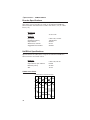
Compumotor
OEM670T
OEM675T
OEM670SD OEM675SD
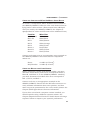
Servo Drive User Guide
Compumotor Division
Parker Hannifin Corporation
p/n 88-013599-01 E
Important User Information
Installation & Operation of Compumotor Equipment
It is important that Compumotor motion control equipment is installed and operated in such a
way that all applicable safety requirements are met. It is your responsibility as a user to ensure
that you identify the relevant standards and comply with them. Failure to do so may result in
damage to equipment and personal injury. In particular, you should review the contents of the
user guide carefully before installing or operating the equipment.
Under no circumstances will the suppliers of the equipment be liable for any incidental,
consequential, or special damages of any kind whatsoever, including but not limited to lost
profits arising from or in any way associated with the use of the equipment or this user guide.
Safety Warning
High-performance motion control equipment is capable of producing rapid movement and very
high forces. Unexpected motion may occur especially during the development of controller
programs. KEEP CLEAR of any machinery driven by stepper or servo motors and never touch
them while they are in operation.
High voltages exist within enclosed units, on rack system backplanes, and on transformer
terminals. KEEP CLEAR of these areas when power is applied to the equipment.
Parker Compumotor constantly strives to improve all of its products. We reserve the right to
modify equipment and user guides without prior notice. No part of this user guide may be
reproduced in any form without prior consent from Parker Compumotor.
For assistance in the United States, contact:
For assistance in Europe, contact:
Compumotor Division of Parker Hannifin
5500 Business Park Drive
Rohnert Park, CA 94928
Telephone: (800) 358-9070
Fax: (707) 584-8015
Parker Digiplan
21 Balena Close
Poole, Dorset
England BH17 7DX
Telephone: 0202-690911
Fax: 0202-600820
Compumotor
© Compumotor Division of Parker Hannifin 1998 All rights reserved
OEM670/OEM675 • Preface
OEM670/OEM675 Servo Drive User Guide
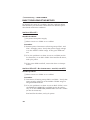
Revision E Change Summary
The following is a summary of the primary technical changes
to this user guide since the last version was released. This
user guide, p/n 88-013599-01 E (released on May 1, 1998),
supersedes 88-013599 D.
OEM SERIES MOTORS ARE OBSOLETE
OEM2300, OEM2303, OEM3400, and OEM3401 motors are
no longer sold by Compumotor. Information about these
motors appears has been removed from this user guide.
SM SERIES AND NEOMETRIC SERIES MOTORS ADDED
We have added Compumotor servo motors to this user guide.
For information about SM Series and NeoMetric Series servo
motors, see Chapter ➂ Specifications (page 57).
OEM675 DRIVE ADDED
Information for Compumotor's new OEM675T Drive and new
OEM675SD Drive has been added throughout this user guide.
OEM670SD USER GUIDE OBSOLETED
The OEM670SD Step & Direction Drive previously had its own
user guide. Information for the OEM670SD and the new
OEM675SD can now be found throughout this user guide.
OEM670X/OEM675X USER GUIDE ADDED
Information for the OEM670X previously appeared in this
user guide. A separate user guide now contains information
for the OEM670X and the new OEM675X.
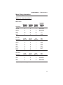
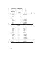
RESISTOR SELECTION SIMPLIFIED (PG. 18)
A new table (page 18) simplifies selection of response and
foldback resistors for Compumotor motors.
CE AND LVD INFORMATION (PG. 163)
CE and LVD installation information begins on page 163.
1
Preface • OEM670/OEM675
Product Type:
OEM670T, OEM675T Torque Servo Drive
OEM670SD, OEM675SD Step & Direction Servo Drive
The above products are in compliance with the requirements
of directives
• 72/23/EEC Low Voltage Directive
• 93/68/EEC CE Marking Directive
The OEM670/OEM675, when installed according to the
procedures in the main body of this user guide, may not
necessarily comply with the Low Voltage Directive (LVD) of the
European Community. To install the OEM670/OEM675 so
that it complies with LVD, you must follow the additional
procedures described in Appendix A, LVD Installation Instructions. If you do not follow these instructions, the LVD protection of the product may be impaired.
The OEM670/OEM675 Series of drives are sold as complex
components to professional assemblers. As
components, they are not required to be compliant with
Electromagnetic Compatibility Directive 89/336/EEC. However, information is offered in Compumotor's EMC Installation
Guide on how to install the OEM670/OEM675 in a manner
most likely to minimize the effects of drive emissions and to
maximize the immunity of drives from externally generated
interference.
Compumotor Division
2
OEM670/OEM675 • Preface
C O N T E N T S
PREFACE ....................................................................... 5
1 INTRODUCTION ......................................................... 7
Description .................................................................................................................... 7
Operation & Block Diagram .......................................................................................... 7
Related Products ........................................................................................................ 10
OEM670 versus OEM675: How to Choose? .............................................................. 14
2 INSTALLATION ........................................................ 15
OEM670/OEM675 Ship Kit ......................................................................................... 15
Installing Selectable Resistors .................................................................................... 16
Resistor Selection for Compumotor Motors ........................................................ 18
Resistor Selection for Non-Compumotor Motors ................................................ 19
Drive Mounting ............................................................................................................ 20
Drive Dimensions ................................................................................................ 20
Panel Layout ....................................................................................................... 21
Motor Mounting ........................................................................................................... 24
Connecting a Motor to the Drive ................................................................................. 28
Connecting Compumotor SM and NeoMetric Series Motors .............................. 29
Connecting Motors from Other Vendors ............................................................. 29
Connecting a Brushed DC Servo Motor .............................................................. 30
Shielded Motor Cables ........................................................................................ 30
Motor Grounding ................................................................................................. 30
OEM670T/OEM675T Inputs and Outputs ................................................................... 31
Command Input .................................................................................................. 31
Enable Input ........................................................................................................ 35
Fault Output ........................................................................................................ 36
Current Monitor ................................................................................................... 37
Ground Pins – Analog and Digital ....................................................................... 38
OEM670SD/OEM675SD Inputs and Outputs ............................................................. 39
Clockwise and Counterclockwise – Definitions ................................................... 39
Required Inputs ................................................................................................... 40
Optional Inputs and Outputs ............................................................................... 43
Connecting a Power Supply ........................................................................................ 48
Tuning – OEM670T/OEM675T Torque Drive ............................................................. 51
Tuning – OEM670SD/OEM675SD Step & Direction Drive ......................................... 51
3 SPECIFICATIONS .................................................... 57
Specifications: OEM670T/OEM675T Torque Drive .................................................... 58
Specifications: OEM670SD/OEM675SD Drive ........................................................... 60
Motor Specifications .................................................................................................... 62
Speed/Torque Curves ................................................................................................. 67
Motor Dimensions ....................................................................................................... 69
Encoder Specifications ............................................................................................... 72
Hall Effect Specifications ............................................................................................ 72
Motor Wiring Information ............................................................................................. 73
3
Preface • OEM670/OEM675
C O N T E N T S
4 SPECIAL INTERNAL CIRCUITS ............................. 75
Short Circuit Protection ............................................................................................... 75
Undervoltage ............................................................................................................... 78
Overvoltage ................................................................................................................. 79
Overtemperature ......................................................................................................... 80
Response Circuit ......................................................................................................... 82
Motor Inductance Affects Feedback ................................................................... 84
Selecting a Response Resistor ........................................................................... 89
Current Foldback ........................................................................................................ 93
Resistor Selection ............................................................................................... 99
How Long Will Foldback Protect Your System? ............................................... 103
5 HALL EFFECT SENSORS ..................................... 105
Hall Effect Sensors and Commutation ...................................................................... 105
The Hall Effect .................................................................................................. 106
Hall Effect Sensors ........................................................................................... 107
Hall Effect Sensors Used Inside Brushless Motors ........................................... 108
Windings in a Three Phase Brushless Motor .................................................... 109
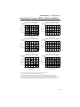
The Six Possible Hall States ............................................................................. 110
Commutation Based on Hall States .................................................................. 113
Connecting Motors from Other Vendors ................................................................... 115
Improper Wiring Can Result in Poor Performance ............................................ 115
Trial and Error Method ...................................................................................... 116
6 POWER SUPPLY SELECTION .............................. 117
How Much Power Does Your System Need? ........................................................... 118
Peak Power—A Calculation Method ................................................................. 118
Peak Power—A Graphical Method ................................................................... 125
Friction, Gravity, and Different Move Profiles ................................................... 130
Power Requirements—An Empirical Method .................................................... 133
Average Power Calculations ............................................................................. 136
Regeneration ............................................................................................................ 136
Power Flow During Deceleration ...................................................................... 137
Energy During Regeneration ............................................................................ 137
Regeneration Curves ........................................................................................ 140
What Voltage Do You Need? .................................................................................... 143
Power Supply Choices .............................................................................................. 145
Powering Multiple Axes ............................................................................................. 151
7 TROUBLESHOOTING ............................................ 153
Basic Troubleshooting Method ................................................................................. 156
Miscellaneous Problems ........................................................................................... 160
Product Return Procedure ........................................................................................ 162
APPENDIX: LVD INSTALLATION ............................. 163
INDEX ......................................................................... 167
4
OEM670/OEM675 • Preface
P
R
E
F A
C
E
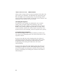
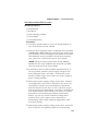
ABOUT THIS USER GUIDE
You may not need to read this user guide from cover to cover!
You can find essential information in the first three chapters—a product description in Chapter 1, installation instructions in Chapter 2, and specifications for the drive and motors
in Chapter 3. This may be all you need to use the OEM670/
OEM675.
Later chapters contain additional information about selected
topics. Read them if you need a deeper understanding about
these topics.
Special internal circuits, including an extended discussion of
the current foldback circuit and the response circuit, are
covered in Chapter 4. This chapter may interest you if you
want to achieve optimum performance from the drive by
adjusting the selectable resistors.
Hall effect sensors, and the way they affect commutation in
brushless servo motors, are described in Chapter 5. If you use
motors from manufacturers other than Compumotor, you may
need this information to determine how to connect your motor
to the drive.
Power supply selection is covered in Chapter 6. Read this
chapter for information about calculating the power your
system requires, how regeneration affects power supplies, and
how you can specify a power supply for your system.
Troubleshooting procedures are covered in Chapter 7.
5
Preface • OEM670/OEM675
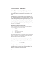
NAMES IN THIS USER GUIDE
This user guide describes four products:
•
OEM670T Torque Servo Drive
•
OEM675T Torque Servo Drive
•
OEM670SD Step & Direction Servo Drive
•
OEM675SD Step & Direction Servo Drive
In this user guide, when we use the name OEM670/OEM675,
it will apply to all four products. Because most features are
identical for the four products, this will usually be the case.
If we need to point out differences between the products, for
features that are not identical, we will specifically call the
product by its full name—OEM670T, OEM675T, OEM670SD,
or OEM675SD.
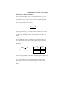
WARNINGS AND CAUTIONS
Warning and caution notes alert you to problems that may
occur if you do not follow the instructions correctly. Situations that may cause bodily injury are presented as warnings.
Situations that may cause system damage are presented as
cautions.
A typical warning note is shown below.
WARNING
Do not touch the motor immediately after it has been in use for an extended
period of time. The motor may be hot.
A typical caution note is shown below.
CAUTION
Do not turn on power unless the motor's Hall effect sensors, Hall +5, and
Hall GND are connected to the drive. The motor may be destroyed by
overheating if these connections are not made.
6
OEM670/OEM675 • ➀ Introduction
C
H
A
P
T
E
R
➀
Introduction
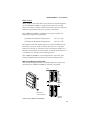
OEM670T/OEM675T DESCRIPTION
The OEM670T/OEM675T is a torque servo drive designed to
operate standard 3 phase brushless DC servo motors
equipped with Hall effect sensors, or equivalent feedback
signals. It can also operate brushed DC servo motors. It is a
high-performance module around which the Original Equipment Manufacturer (OEM) can design a motion control system. The drive offers a basic set of features designed to meet
the needs of most customers. It is compatible with standard
industry servo controllers, and is intended to be used in
positioning applications. It uses three-state current control for
efficient drive performance and cooler motor operation.
The OEM670T/OEM675T is small and convenient to use. It
installs with only two screws (the screws also provide grounding and captivate the cover). Its rightangle screw terminal
allows side-by-side mounting, and its small footprint maximizes cabinet space. The snap-on molded cover is removable
for drive configuration, and helps provide a barrier against
environmental contamination. The drive is the same size as a
3U Eurorack card. Its standard 25 pin D-connector is compatible with universally available connectors.
The drive is designed for manufacturability and reliability. It
uses surface mount components and a custom designed ASIC
to conserve space, reduce cost, and improve reliability. More
than 90% of the components are auto inserted, which reduces
assembly time and cost, and further improves reliability.
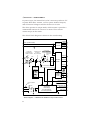
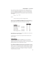
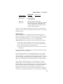
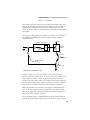
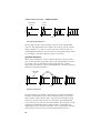
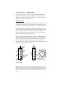
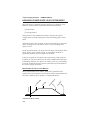
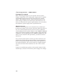
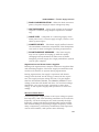
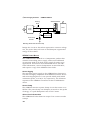
OEM670T/OEM675T OPERATION & BLOCK DIAGRAM
The OEM670T/OEM675T Torque Drive requires a single
external power supply. The drive accepts 24VDC to 75VDC for
7
➀ Introduction • OEM670/OEM675
its power input. Its internal DC-to-DC converter produces +5V
to power Hall effect sensors, ±15V to power isolated outputs,
and all internal voltages used for the drive’s circuits.
The drive operates in torque mode, which means it provides a
commanded amount of current to a motor. This current
causes torque in the motor.
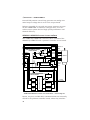
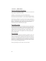
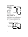
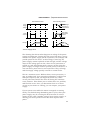
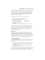
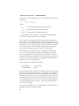
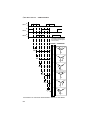
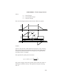
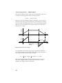
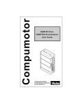
The drive’s block diagram is shown in the next drawing.
+15VDC
-15VDC
VDC+ (24VDC-75VDC)
DC to DC
Converter
VDC- (Ground)
Input Signals
Can Range From
-10VDC to +10VDC
Command+
Foldback Circuit
Can Clamp
Torque Command
Phase A
10KΩ
10KΩ
10KΩ
Current Loop
Error
Response
Amplifier Resistor R22
(User Selectable)
Hall +5V
Hall GND
+
Σ
PWM
ASIC
−
POWER
STAGE
Phase B
10KΩ
Command -
Phase C
CURRENT
FOLDBACK
CIRCUIT
Current Feedback
+5V
1K 1K 1K
R23
R24
Hall 1
COMMUTATION
LOGIC
R25
User
Selectable
Resistors
Hall 2
Hall 3
Current Monitor +
Current Monitor -
Ground to Enable
+5V
2.49KΩ
Enable In
Ground
22KΩ
22KΩ
FAULT & PROTECTION CIRCUITS
Short Circuit
Undervoltage
Over Temperature
Excess Regeneration
Green Power LED
Red Fault LED
Fault Output
(Low = No Fault)
Block Diagram — OEM670T & OEM675T Torque Servo Drive
8
OEM670/OEM675 • ➀ Introduction
Input to the drive is a voltage signal called command input. It
can range from -10VDC to +10VDC. Output current is scaled
so that each volt of command input corresponds to 1.2A of
output current. For example, a command input of 5V results
in a 6A output current. The maximum command input of 10V
results in the full 12A output current.
The command input terminals can accommodate single
ended, differential, or isolated controller wiring systems.
When the command input signal enters the drive, it is amplified, sent through a foldback circuit (which may or may not be
active) and an inverter, and summed with a current feedback
signal that is proportional to the actual output current.
An error signal—the difference between commanded and
actual output current—goes through an error amplifier. The
amplifier’s output controls a pulse width modulation (PWM)
circuit. If actual current is too low, the PWM circuit will send
longer pulses to the power stage. These pulses keep the stage
turned on longer, which results in more output current. If
actual current is too high, the PWM circuit sends shorter
pulses, resulting in less current.
A response resistor affects the signal level that goes into the
PWM circuit. The user can choose a value for this resistor that
produces the best current loop gain and system dynamics for
a particular motor.
The power stage has three outputs—each connects to a
particular motor coil. The drive gets inputs from the motor’s
Hall effect sensors, and determines which of six possible
positions the rotor is in. It then uses a six-state commutation
technique to send current into one coil and out of another (the
third coil receives no current). The current creates a torque on
the rotor, and the rotor turns to the next position. The drive
reads the new position from the Hall sensors, and switches
current to a different combination of coils. The rotor turns
further, and the process repeats. (The drive can also be
configured to commutate brushed servo motors.)
The drive has several fault and protection circuits. These
monitor temperature, regeneration, undervoltage, and short
circuits. They can shut down the drive if limits are exceeded.
LEDs indicate power and fault status.
9
➀ Introduction • OEM670/OEM675
A foldback circuit monitors motor current, and protects the
motor from overheating due to prolonged high currents. The
user can install resistors to set levels for peak current,
foldback current, and time constant. When the circuit invokes
foldback, it clamps the command input signal at a voltage
that reduces motor current to the preset level. After a period
of time, the circuit may release its clamp on the command
input signal, and normal operations can continue.
The drive has several other inputs and outputs. An enable
input must be grounded to enable the drive. A fault output is
held low if there are no faults. A current monitor output
provides a voltage scaled to represent the actual output
current. It can range from -10V to +10V, with one volt corresponding to 1.2 amps of output current.
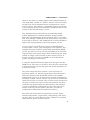
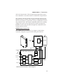
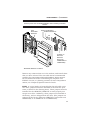
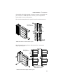
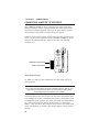
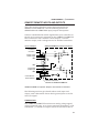
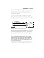
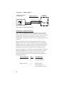
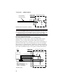
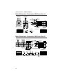
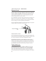
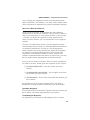
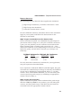
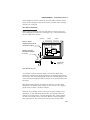
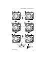
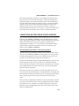
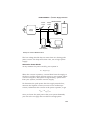
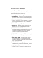
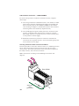
RELATED PRODUCTS
The OEM670T/OEM675T is the “building block” in a family of
servo drives. It has an internal slot where an additional circuit
board can be inserted to make a different product.
or
mot
pu
Com
M
OE
s
e
r
i
e
s
QUE
IVE
T
10
DR
Additional Circuit Board Can Mount Internally
O
Both Boards Slide Into Cover
Together as One Unit
O
C+
VD CVD D
GN
LL +5V
HA LL L 1
HA HALL 2
L
HALL 3
HA E A
AS B
PHASE C
H
P ASE
PH
SERV
R
Additional Circuit Board
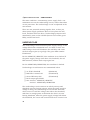
OEM670/OEM675 • ➀ Introduction
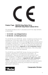
The additional circuit board is inserted at the factory, at the
time of manufacture. Externally, the new product looks just
like the OEM670T/OEM675T, except that the label is a
different color.
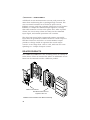
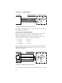
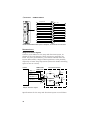
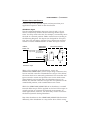
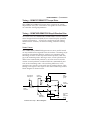
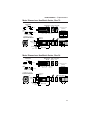
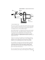
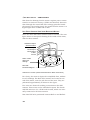
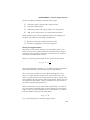
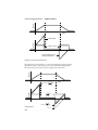
OEM670SD & OEM675SD STEP & DIRECTION SERVO DRIVE
The OEM670SD/OEM675SD Step & Direction Servo Drive
consists of the OEM670T/OEM675T with a position controller
circuit board added.
VDC+
VDC–
OEM670T/OEM675T
TORQUE DRIVE
CIRCUIT BOARD
+
Σ
−
PWM
ASIC
DC/DC
Encoder +5V
Converter
GND
POWER
STAGE
Phase A
Phase B
Phase C
MOTOR
FOLDBACK
COMMUT
LOGIC
FAULT &
PROTECTION
CIRCUITS
Enable
Current
Monitor
Fault
Output
Encoder
STEP & DIRECTION
CIRCUIT BOARD
Torque
Command
Integ. Disable
Deriv. Reduce
LEDs
Hall 1
Hall 2
Hall 3
P
I
D
PID
DISABLE
12-Bit DAC
CPE 1 Input
CPE 2 Input
Shutdown
Input
Step Input
Position
Error
16-Bit
Counter
Step-Count
Difference
+
Σ
FAULT
LATCH
Velocity
Monitor
Up/Down
Count
−
Direction
Input
Synch. Circuitry
Encoder
Count
Encoder
Direction
Isolated
Fault
Output
Quadrature
Detect
Channel A
Channel B
Position
Feedback
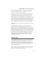
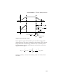
Block Diagram – OEM670SD/OEM675SD Step & Direction Servo Drive
The controller accepts step and direction position commands
from an indexer. It uses encoder signals for feedback. Its
11
➀ Introduction • OEM670/OEM675
internal PID position control loop generates an analog command output voltage that is sent to the torque board.
Indexers intended for use with step motor systems can operate the OEM670SD. It emulates a stepper drive, but can
achieve servo system levels of high speed performance and
thermal efficiency.
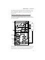
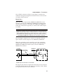
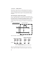
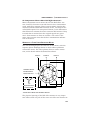
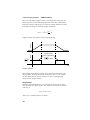
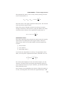
OEM670X & OEM675X POSITION CONTROLLER/DRIVE
The OEM670X/OEM675X Controller/Drive consists of the
OEM670T/OEM675T with a position controller circuit board.
VDC+
VDCOEM670T/OEM675T TORQUE
CIRCUIT BOARD
+
RS-232C
Σ
Commun.
Inputs
Outputs
PWM
ASIC
−
DC/DC
Encoder +5V
Converter
GND
POWER
STAGE
Phase A
Phase B
Phase C
MOTOR
FOLDBACK
COMMUT
LOGIC
Enable
FAULT/PROTECTION CIRCUITS
LEDs
Hall 1
Hall 2
Hall 3
Current
Monitor
Fault
Encoder
Torque Command
POSITION CONTROLLER
CIRCUIT BOARD
RS-232C
Comm
INPUTS
OUTPUTS
M
I
C
R
O
P
R
O
C
E
S
S
O
R
PID
+
Σ
−
Position
Feedback
ENABLE
FAULT
MONITOR
OEM670X/OEM675X Position Controller/Drive — Block Diagram
Inputs, outputs, and RS-232C communications are internally
routed to the position controller board, where they interface
12
OEM670/OEM675 • ➀ Introduction
with a microprocessor. The microprocessor generates a position command. It can also enable or disable the torque board.
The position controller board receives feedback about actual
position from an encoder, and compares commanded position
with actual position. It generates a torque command to correct
any position errors. The torque command (which is an analog
voltage) then goes to the torque board, passes through the
foldback circuit, and proceeds through the remainder of the
torque board’s circuits.
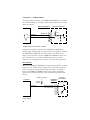
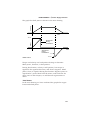
OEM070 SERVO CONTROLLER
The OEM070 Servo Controller is a compact, stand-alone
controller designed to operate with analog servo drives.
SERVO DRIVE
0
07
M
OE
POWER
OUTPUT
POWER
INPUT
MOTOR
ER
W
PO
+5V
V
+15
5V
-1
D
GN
Encoder
or
mot
pu
Com
Torque Command
Output
POWER INPUT
+5V
+15V
–15V
Ground
RS-232C
Commun.
RS-232C
Comm
Inputs
INPUTS
Outputs
OUTPUTS
+
Fault
Input
DAC
OEM070 SERVO CONTROLLER
M
I
C
R
O
P
R
O
C
E
S
S
O
R
Enable
Output
PID
Σ
−
ENABLE
Position
Feedback
FAULT
MONITOR
OEM070 Servo Controller – Block Diagram
13
➀ Introduction • OEM670/OEM675
The OEM070 contains the same position controller board
used in the OEM670X/OEM675X. The board is packaged by
itself in a minimum depth, small footprint housing. It controls
motor torque or velocity with a ±10V command output signal.
Through its I/O and RS-232C ports, the OEM070 can interface with external devices such as incremental encoders,
switches, computers, and programmable control units.
SM AND NEOMETRIC SERIES SERVO MOTORS
Compumotor offers SM Series and NeoMetric Series servo
motors designed to operate with OEM Series servo drives.
Each motor is equipped with Hall effect outputs and an
encoder.
OEM670 versus OEM675: How to Choose?
You can decide whether to use an OEM670 or OEM675 based
upon the motor you choose for your application.
Compumotor SM Series Motor: choose an OEM675. Its current
compensation loop is optimized for SM (slotless) motors.
Compumotor NeoMetric Series Motor: choose an OEM670. Its
current compensation loop is optimized for NeoMetric (slotted)
motors.
Non-Compumotor Motor: If yours is a non-Compumotor motor,
examine the motor specification tables for Compumotor motors in
Chapter ➂ Specifications, and find a motor with inductance and
resistance similar to yours. If the similar motor is an SM Series
motor, choose an OEM675. If the similar motor is a NeoMetric
Series motor, choose an OEM670.
If you cannot find a similar motor in the specification tables, you
may need to contact a Compumotor Applications Engineer (800358-9070) for advice on choosing a drive for use with your motor.
14
OEM670/OEM675 • ➁ Installation
C
H
A
P
T
E
R
➁
Installation
Complete the following installation steps before you use the
OEM670/OEM675 drive.
INSTALLATION STEPS
➀
➁
➂
➃
➄
➅
➆
➇
Verify shipment is correct.
Install selectable resistors.
Mount the drive.
Mount the motor.
Connect the motor to the drive.
Connect inputs, outputs, and controller.
Connect a power supply to the drive.
Tune the drive (OEM670SD/OEM675SD only).
The sections in this chapter give basic instructions about how
to complete each of these steps.
OEM670/OEM675 SHIP KIT
Inspect the OEM670/OEM675 upon receipt for obvious
damage to its shipping container. Report any damage to the
shipping company. Parker Compumotor cannot be held
responsible for damage incurred in shipment. You should
receive one or more drives, depending upon what you ordered.
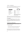
Compare your order with the units shipped.
Component
OEM670 or OEM675 Drive
Resistor Kit
Accessories
OEM670/OEM675 User Guide
Heatsink
Part Number
OEM670T, OEM675T,
OEM670SD, OEM675SD
73-016979-01
88-013599-01
OEM -HS1
User guides are not sent with each product. They are available
upon request. Please order user guides as needed.
15
➁ Installation • OEM670/OEM675
The following SM and NeoMetric Series servo motors are
designed to be used with the OEM670/OEM675. Compare
your order with the motors shipped.
Motor Size
Size 16
Size 23
Size 34
Size 70mm
Part Number
SM160A, SM160B, SM161A, SM161B
SM162A, SM162B
SM230A, SM230B, SM231A, SM231B,
SM232A, SM232B, SM233A, SM233B
NO341D, NO341F, NO342E, NO342F
NO701D, NO701F, NO702E, NO702F
INSTALLING SELECTABLE RESISTORS
You must install four resistors into sockets on the OEM670/
OEM675’s circuit board. Three of these are foldback resistors;
they determine the parameters for the current foldback circuit, which can protect your motor from overheating due to
prolonged high currents. The fourth resistor is a response
resistor—it affects the gain and frequency response of the
current loop.
The drive you ordered determines whether or not resistors are
installed when it arrives:
OEM670 – Ships from factory with resistors installed. These
resistors are not appropriate for most applications. You
must select other resistors and install them in the drive.
OEM675 – Ships from factory without resistors installed. You
must select and install resistors for the drive to work.
A resistor kit for use with Compumotor SM and NeoMetric
Series motors is included with the drive. Resistors in the kit
have a four digit code. The first three digits are resistance
values; the fourth digit is a multiplier.
Example:
3013 = 301 x 103 = 301KΩ
6492 = 649 x 102 = 64.9 KΩ
Note: zero ohm resistors may be color coded (black band)
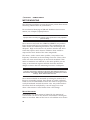
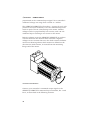
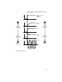
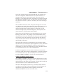
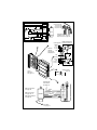
To install selectable resistors, remove the drive’s molded
plastic cover. Apply pressure to the D-connector while you
hold the cover's sides. The circuit board will slide out. The
resistors and their sockets are located near the corner of the
board, close to the 25 pin D-connector, as shown below.
16
OEM670/OEM675 • ➁ Installation
WARNING
Remove power from the OEM670/OEM675 before installing selectable
resistors.
User
Selectable
Resistors
Response Resistor
Foldback Resistors
R25
R24
R23
R22
r
oto
um
mp
Co
M
OE
s
e
r
i
e
s
QUE
T
IVE
O
C+
VD CVD D
GN V
L
L +5
HA LL L 1
HA HALL 2
L
HALL 3
HA E A
AS B
PHASE C
H
P ASE
PH
SERV
R
O
Jumpers on
First Four
Positions
(except on
OEM670SD or
OEM675SD)
DR
Selectable Resistor Locations
Remove any resistors that are in the sockets, and install those
that you have selected. The next table shows recommended
resistors for Compumotor SM and NeoMetric Series motors.
For full details on further customizing the response and
foldback circuits, or choosing resistors for non-Compumotor
motors, see Chapter ➃ Special Internal Circuits.
NOTE: A 34 pin header is located below the selectable resistors. Four jumpers should be installed in the first four positions, as shown in the drawing above. These jumpers must be
installed for the OEM670T/OEM675T to work properly as a
torque servo drive. Ordinarily, these jumpers are installed at
the factory, and are shipped with the drive. (The jumpers are
removed at the factory when an OEM670T is converted to an
OEM670SD, or an OEM675T to an OEM675SD.)
17
➁ Installation • OEM670/OEM675
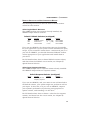
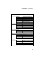
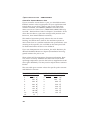
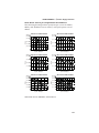
RESISTOR SELECTION FOR COMPUMOTOR MOTORS
If your drive is an OEM670, use the first table below to select
resistors for use with Compumotor's SM or NeoMetric Series
motors. If your drive is an OEM675, use the second table.
OEM670 – Resistors for SM and Neometric Motors at 75VDC*
Motor
SM160A**
SM160B**
SM161A
SM161B
SM162A
SM162B
SM230A
SM230B
SM231A
SM231B
SM232A
SM232B
SM233A
SM233B
NO701D/NO341D
NO701F/NO341F
NO702E/NO342E
NO702F/NO342F
R22, Rresponse R23, Tc-therm
100 KΩ
5.1 MΩ
500 KΩ
10 MΩ
100 KΩ
5.1 MΩ
301 KΩ
10 MΩ
90.9 KΩ
5.1 MΩ
205 KΩ
10 MΩ
100 KΩ
5.1 MΩ
301 KΩ
10 MΩ
64.9 KΩ
5.1 MΩ
205 KΩ
10 MΩ
40.2 KΩ
5.1 MΩ
150 KΩ
10 MΩ
30.1 KΩ
5.1 MΩ
100 KΩ
10 MΩ
205 KΩ
10 MΩ
750 KΩ
10 MΩ
750 KΩ
10 MΩ
604 KΩ
10 MΩ
R24, Ipk-tune
348 KΩ (5 A)
64.9 KΩ (10 A)
450 KΩ (4 A)
124 KΩ (8 A)
450 KΩ (4 A)
124 KΩ (8 A)
348 KΩ (5 A)
64.9 KΩ (10 A)
450 KΩ (4 A)
124 KΩ (8 A)
450 KΩ (4 A)
124 KΩ (8 A)
450 KΩ (4 A)
124 KΩ (8 A)
249 KΩ (6 A)
90.9 KΩ (9 A)
182 KΩ (7 A)
90.9 KΩ (9 A)
R24, Ipk-final
150 KΩ (7.5 A)
0 Ω (12 A)
249 KΩ
(6 A)
0 Ω (12 A)
249 KΩ
(6 A)
0 Ω (12 A)
150 KΩ (7.5 A)
0 Ω (12 A)
249 KΩ
(6 A)
0 Ω (12 A)
249 KΩ
(6 A)
0 Ω (12 A)
249 KΩ
(6 A)
0 Ω (12 A)
90.9 KΩ
(9 A)
0 Ω (12 A)
64.9 KΩ (10 A)
0 Ω (12 A)
R25, Ifold
500 KΩ
100 KΩ
500 KΩ
100 KΩ
500 KΩ
100 KΩ
500 KΩ
100 KΩ
500 KΩ
100 KΩ
500 KΩ
100 KΩ
500 KΩ
100 KΩ
165 KΩ
100 KΩ
165 KΩ
100 KΩ
(1.5 A)
(2.8 A)
(1.5 A)
(2.8 A)
(1.5 A)
(2.8 A)
(1.5 A)
(2.8 A)
(1.5 A)
(2.8 A)
(1.5 A)
(2.8 A)
(1.5 A)
(2.8 A)
(2.0 A)
(2.8 A)
(2.0 A)
(2.8 A)
R25, Ifold
500 KΩ
100 KΩ
500 KΩ
100 KΩ
500 KΩ
100 KΩ
500 KΩ
100 KΩ
500 KΩ
100 KΩ
500 KΩ
100 KΩ
500 KΩ
100 KΩ
(1.5 A)
(2.8 A)
(1.5 A)
(2.5 A)
(1.5 A)
(2.5 A)
(1.5 A)
(2.8 A)
(1.5 A)
(2.5 A)
(1.5 A)
(2.5 A)
(1.5 A)
(2.5 A)
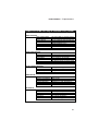
OEM675 – Resistors for SM Motors at 75VDC*
Motor
SM160A
SM160B
SM161A
SM161B
SM162A
SM162B
SM230A
SM230B
SM231A
SM231B
SM232A
SM232B
SM233A
SM233B
R22, Rresponse R23, Tc-therm R24, Ipk-tune
249 KΩ
5.1 MΩ
348 KΩ (5 A)
750 KΩ
10 MΩ
64.9 KΩ (10 A)
301 KΩ
5.1 MΩ
450 KΩ (4 A)
750 KΩ
10 MΩ
124 KΩ (8 A)
205 KΩ
5.1 MΩ
450 KΩ (4 A)
402 KΩ
10 MΩ
124 KΩ (8 A)
402 KΩ
5.1 MΩ
348 KΩ (5 A)
1 MΩ
10 MΩ
64.9 KΩ (10 A)
402 KΩ
5.1 MΩ
450 KΩ (4 A)
604 KΩ
10 MΩ
124 KΩ (8 A)
205 KΩ
5.1 MΩ
450 KΩ (4 A)
500 KΩ
10 MΩ
124 KΩ (8 A)
500 KΩ
5.1 MΩ
450 KΩ (4 A)
750 KΩ
10 MΩ
124 KΩ (8 A)
R24, Ipk-final
150 KΩ (7.5 A)
0 Ω (12 A)
249 KΩ
(6 A)
0 Ω (12 A)
249 KΩ
(6 A)
0 Ω (12 A)
150 KΩ (7.5 A)
0 Ω (12 A)
249 KΩ
(6 A)
0 Ω (12 A)
249 KΩ
(6 A)
0 Ω (12 A)
249 KΩ
(6 A)
0 Ω (12 A)
* For supply voltages less than 75VDC, calculate R22 using the following equation: R22new = (R22old • Vbus)/75,
where R22old is the value from the table above (at 75VDC). R23, R24, R25 remain the same as for 75VDC.
**Although the OEM670 can be used with the SM160A and SM160B motors, Compumotor recommends
using the OEM675 for optimum performance with the SM160A and SM160B motors.
R24 – “pk-tune” and “pk-final”
Note that there are two values recommended for R24. Use the
first value (pk-tune) when you begin your tuning procedure.
This keeps peak currents low, to avoid the damaging currents
that instability during tuning can cause. As you refine your
tuning settings, replace R24 with the second value (pk-final), if
your application requires more torque.
18
OEM670/OEM675 • ➁ Installation
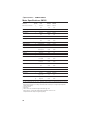
RESISTOR SELECTION FOR NON-COMPUMOTOR MOTORS
The following two sections describe how to choose resistor
values for other motors.
Selecting Foldback Resistors
The OEM670 ships with resistors already installed; the
OEM675 ships without resistors.
Default Foldback Resistors (as shipped)
Res. #:
R25
R24
R23
Function
Foldback Current
Peak Current
Time Constant
OEM670
23.7 KΩ (6A)
Ø Ω (12A)
5.1 MΩ
OEM675
none installed
none installed
none installed
If you use an OEM670, the values above may not be suitable
for your application. If your system cannot withstand the peak
torque, if your controller cannot detect a mechanical jam, or if
you use an OEM675, you should determine foldback resistor
values appropriate to your application and install them in
your drive.
For full details about how to choose foldback resistor values,
and about how the foldback circuit works, see Chapter ➃
Special Internal Circuits.
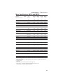
Selecting a Response Resistor
The OEM670 ships with a response resistor already installed:
the OEM675 ships without a response resistor.
Default Response Resistor (as shipped)
Res. #:
R22
Function
Optimize gain and
frequency response
OEM670
100 KΩ
OEM675
none installed
If you use an OEM670, and your motor is not well matched to
the default resistor, your system might not perform as well as
you expect. In this case, or if you use an OEM675, improve
your system’s performance by selecting an appropriate response resistor, and installing it in the drive.
For full details about how to choose a value for the response
resistor, and about how the circuit works, see Chapter ➃
Special Internal Circuits.
19
➁ Installation • OEM670/OEM675
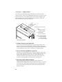
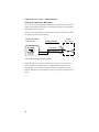
0.420
(10.67)
DRIVE MOUNTING
This surface must be
thermally coupled to a
cold plate in most
applications
2x 0.177 (4.496)
thru (clearance
for #8 (M4)
mounting screw)
1.625 (41.28)
3.555 (90.30)
3.315 (84.20)
SER
POWER
FAULT
VDC+
VDCHALL GND
HALL +5V
HALL 1
HALL 2
HALL 3
PHASE A
PHASE B
PHASE C
1.000 (25.40)
7.000 (177.80)
Mounting Clearance
ORQU
IVE
T
OEM
s
e
r
i
e
s
E
5.000 (127.00)
5500 Business Park Dr.
Rohnert Park, CA 94928
Compumotor
VO DR
Compumotor
4.650 (118.11)
0.175 (4.45)
0.812 (20.62)
1.000 (25.40)
2.000 (50.80)
Mounting Clearance
Exposed aluminum
for electrical
grounding
0.335
(8.51)
Dimensions in
inches (millimeters)
OEM670/OEM675 Dimensions
DRIVE DIMENSIONS
The OEM670/OEM675 is designed to minimize panel area, or
footprint, in an equipment cabinet. Dimensions are shown in
the drawing. You can mount the drive in a “minimum depth”
configuration if you use an optional heatsink. (See below.)
20
OEM670/OEM675 • ➁ Installation
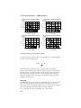
PANEL LAYOUT
Move profiles and loads affect the amount of heat dissipated
by the OEM670/OEM675. Applications with low average
power (less than 3 Amps continuous motor current) and mild
ambient temperatures may not require a heatsink.
The OEM670/OEM675 is designed to operate within the
following temperature guidelines:
❏ Maximum Ambient Temperature:
45°C (113°F)
❏ Maximum Heatsink Temperature
45°C (113°F)
For applications with higher power or elevated ambient temperatures, you may need to mount the drive in a way that
removes heat from it. The drive uses a heatplate design as a
pathway to dissipate its excess heat; it should be mounted to
a heatsink or a suitable heat sinking surface.
The OEM670/OEM675 is overtemperature protected. (See
Chapter ➃ Special Internal Circuits for more information.)
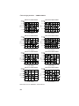
Mounting Without a Heatsink
The next drawing shows the recommended panel layout for
mounting the OEM670/OEM675 without a heatsink.
0.375
(9.52)
Compumotor
OEM
OEM
ORQU
POWER
FAULT
VDC+
VDCHALL GND
HALL +5V
HALL 1
HALL 2
HALL 3
PHASE A
PHASE B
PHASE C
VDC+
VDCHALL GND
HALL +5V
HALL 1
HALL 2
HALL 3
PHASE A
PHASE B
PHASE C
2 (50.80)
4.65
(118.11)
Compumotor
OEM
OEM
s
e
r
i
e
s
ORQU
ORQU
O
D RI
IVE
SER
SER
VO DR
Panel Layout (Without a Heatsink)
T
s
e
r
i
e
s
E
T
Compumotor
E
Dimensions in
inches (millimeters)
2.35 (59.69)
IVE
C+
VD CVD D
GN
LL +5V
HA LL L 1
HA HALL 2
L 3
A
H LL
HA E A
AS B
PHASE C
PHASE
PH
VO DR
V
TO
IVE
IVE
VO DR
POWER
FAULT
QUE
SE R
VE
VO DR
s
e
r
i
e
s
R
SER
M
OE
SER
or
mot
mpu
Co
T
s
e
r
i
e
s
ORQU
E
s
e
r
i
e
s
E
T
Compumotor
POWER
FAULT
POWER
FAULT
VDC+
VDCHALL GND
HALL +5V
HALL 1
HALL 2
HALL 3
PHASE A
PHASE B
PHASE C
VDC+
VDCHALL GND
HALL +5V
HALL 1
HALL 2
HALL 3
PHASE A
PHASE B
PHASE C
2 (50.80)
Minimum
21
➁ Installation • OEM670/OEM675
Mounting With Compumotor Heatsink OEM-HS1
A heatsink designed to work with the OEM670/OEM675 can
be purchased from Compumotor (Part Number OEM-HS1).
This heatsink is sufficient for most applications operating in
45°C (113°F) or lower ambient temperatures.
The drive may be mounted in two different configurations.
One configuration uses a minimum amount of mounting area
(minimum area). The other configuration uses a minimum
amount of mounting depth (minimum depth).
Heatsink dimensions are shown in the next drawing.
1.175
(29.84)
2x #8-32 UNC-2B
Thru One Fin
4.650
(118.11)
2x Ø0.187 (4.75) Thru
0.175
(4.44)
0.200
(5.08)
2x #8-32 UNC-2B Thru
0.637 (16.18)
0.450 (11.43)
4.650
(118.11)
2.100
(53.34)
2.000
(50.8)
0.200
(5.08)
OEM-HS1 Heatsink Dimensions
0.175
(4.44)
1.287
(32.69)
5.000
(127.00)
Dimensions in
inches (millimeters)
Two #8-32 screws are needed to mount the OEM670/
OEM675 to the OEM-HS1 heatsink. Use a star washer on the
bottom screw to ensure proper electrical grounding. Use two
#8 screws to mount the OEM-HS1 to the cabinet.
Do not use a star washer between the back of the OEM670/
OEM675 heatplate and the mounting surface. The mounting
surface must be flat. Use silicone thermal joint compound or
thermal pads to facilitate heat transfer from the drive’s
heatplate to your mounting surface.
22
OEM670/OEM675 • ➁ Installation
A heatsink with holes tapped for metric screws is available. Its
part number is OEM-HS1-M4. Consult your Compumotor
sales guide for more information.
The next drawing shows the panel layout for minimum area.
0.5
(12.7)
Compumotor
OEM
OEM
ORQU
VDC+
VDCHALL GND
HALL +5V
HALL 1
HALL 2
HALL 3
PHASE A
PHASE B
PHASE C
2.35 (59.69)
Compumotor
Compumotor
OEM
OEM
SER
SER
IVE
T
DR
T
ORQU
E
s
e
r
i
e
s
ORQU
E
s
e
r
i
e
s
IVE
O
T
SERV
IVE
POWER
FAULT
VDC+
VDCHALL GND
HALL +5V
HALL 1
HALL 2
HALL 3
PHASE A
PHASE B
PHASE C
VO DR
QUE
R
IVE
IVE
VO DR
s
e
r
i
e
s
4.65
(118.11)
SER
M
OE
O
POWER
FAULT
2 (50.80)
mpu
Co
C+
VD CVD D
GN
LL +5V
HA LL L 1
HA HALL 2
L
HALL 3
HA E A
AS B
PHASE C
PHASE
PH
SER
or
mot
T
s
e
r
i
e
s
ORQU
E
s
e
r
i
e
s
E
T
Compumotor
VO DR
Dimensions in
inches (millimeters)
VO DR
POWER
FAULT
POWER
FAULT
VDC+
VDCHALL GND
HALL +5V
HALL 1
HALL 2
HALL 3
PHASE A
PHASE B
PHASE C
VDC+
VDCHALL GND
HALL +5V
HALL 1
HALL 2
HALL 3
PHASE A
PHASE B
PHASE C
2.5 (63.50)
Minimum
OEM-HS1 Minimum Area Panel Layout
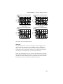
The following drawing shows dimensions for a minimum
depth panel layout.
3
(76.2)
Dimensions in
inches (millimeters)
4.65
(118.81)
2.35 (59.69)
2 (50.80)
or
mot
mpu
Co
M
OE
s
e
r
i
e
s
QUE
O
T
IVE
SERV
R
O
C+
VD CVD D
GN
LL +5V
HA LL L 1
HA HALL 2
L
HALL 3
HA E A
AS B
PHASE C
PHASE
PH
DR
5.95 (160.53)
Minimum
Between Mounting Holes
OEM-HS1 Minimum Depth Panel Layout
23
➁ Installation • OEM670/OEM675
MOTOR MOUNTING
The following guidelines present important points about motor
mounting and its effect on performance.
For mechanical drawings of SM and NeoMetric Series servo
motors, see Chapter ➂ Specifications
WARNING
Improper motor mounting can reduce system performance and jeopardize
personal safety.
Servo motors used with the OEM670/OEM675 can produce
large torques and high accelerations. This combination can
shear shafts and mounting hardware if the mounting is not
adequate. High accelerations can produce shocks and vibrations that require much heavier hardware than would be
expected for static loads of the same magnitude.
The motor, under certain move profiles, can produce lowfrequency vibrations in the mounting structure. These vibrations can cause metal fatigue in structural members if harmonic resonances are induced by the move profiles you are
using. A mechanical engineer should check the machine
design to ensure that the mounting structure is adequate.
CAUTION
Consult a Compumotor Applications Engineer (800-358-9070) before you
machine the motor shaft. Improper shaft machining can destroy the motor’s
bearings. Never disassemble the motor.
Servo motors should be mounted by bolting the motor’s face
flange to a suitable support. Foot mount or cradle configurations are not recommended because the motor’s torque is not
evenly distributed around the motor case. Any radial load on
the motor shaft is multiplied by a much longer lever arm
when a foot mount is used rather than a face flange.
MOTOR HEATSINKING
Performance of a servo motor is limited by the amount of
current that can flow in the motor’s coils without causing the
motor to overheat. Most of the heat in a brushless servo motor
24
OEM670/OEM675 • ➁ Installation
is dissipated in the stator—the outer shell of the motor.
Performance specifications usually state the maximum allowable case temperature. Exceeding this temperature can
permanently damage the motor.
If yours is a demanding application, your motor may become
quite hot. The primary pathway through which you can
remove the heat is through the motor’s mounting flange.
Therefore, mount the motor with its flange in contact with a
suitable heatsink.
Specifications for Compumotor SM and NeoMetric Series servo
motors apply when the motor is mounted to a ten inch by ten
inch aluminum mounting plate, 1/4 inch thick. To get rated
performance in your application, you must mount the motor
to a heatsink of at least the same thermal capability. Mounting the motor to a smaller heatsink may result in decreased
performance and a shorter service life. Conversely, mounting
the motor to a larger heatsink can result in enhanced performance.
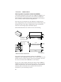
ATTACHING THE LOAD
Your mechanical system should be as stiff as possible. Because of the high torques and accelerations of servo systems,
the ideal coupling between a motor and load would be completely rigid. Rigid couplings require perfect alignment, however, which can be difficult or impossible to achieve. In real
systems, some misalignment is inevitable. Therefore, a certain
amount of flexibility may be required in the system. Too much
flexibility can cause resonance problems, however.
These conflicting requirements are summarized below.
❏ Maximum Stiffness (in the mechanical system)
❏ Flexibility (to accommodate misalignments)
❏ Minimum Resonance (to avoid oscillations)
The best design solution may be a compromise between these
requirements.
25
➁ Installation • OEM670/OEM675
MISALIGNMENT & COUPLERS
The type of misalignment in your system will affect your
choice of coupler.
Parallel Misalignment
The offset of two mating shaft center lines, although the
center lines remain parallel to each other.
Angular Misalignment
When two shaft center lines intersect at an angle other than
zero degrees.
End Float
A change in the relative distance between the ends of two
shafts.
There are three types of shaft couplings: single-flex, doubleflex, and rigid. Like a hinge, a single-flex coupling accepts
angular misalignment only. A double-flex coupling accepts
both angular and parallel misalignments. Both single-flex and
double-flex, depending on their design, may or may not accept
endplay. A rigid coupling cannot compensate for any misalignment.
Single-Flex Coupling
When a single-flex coupling is used, one and only one of the
shafts must be free to move in the radial direction without
constraint. Do not use a double-flex coupling in this situation: it will allow too much freedom and the shaft will rotate
eccentrically, which will cause large vibrations and catastrophic failure. Do not use a single-flex coupling with a
parallel misalignment: this will bend the shafts, causing
excessive bearing loads and premature failure.
Double-Flex Coupling
Use a double-flex coupling whenever two shafts are joined
that are fixed in the radial and angular direction (This is the
most common situation. It results from a combination of
angular and parallel misalignment).
Rigid Coupling
As mentioned above, rigid couplings would be ideal in servo
systems, but are not generally recommended because of
26
OEM670/OEM675 • ➁ Installation
system misalignment. They should be used only if the motor
or load is on some form of floating mounts that allow for
alignment compensation. Rigid couplings can also be used
when the load is supported entirely by the motor’s bearings. A
small mirror connected to a motor shaft is an example of such
an application.
RESONANCE ISSUES
A coupler that is too flexible may cause a motor to overshoot
its commanded position. When the encoder sends a position
feedback signal, the controller will command a correction
move in the opposite direction. If the resonant frequency of
the system is too low (too flexible), the motor may overshoot
again and again. In extreme cases, the system could become
an oscillator.
To solve resonance problems, increase the mechanical stiffness of the system to raise the resonant frequency so that it
no longer causes a problem.
If you use a servo as a direct replacement for a step motor,
you may need to modify your mechanical coupling system to
reduce resonance. For example, we recommend using a
bellows-style coupler with servo motors, rather than the
helical-style coupler that is often used with step motors.
Helical couplers are often too flexible, with resonant frequencies that can cause problems. Bellows couplers are stiffer, and
perform better in servo systems.
27
➁ Installation • OEM670/OEM675
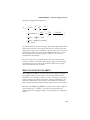
CONNECTING A MOTOR TO THE DRIVE
The OEM670/OEM675 drive is designed to work with threephase brushless motors equipped with Hall effect sensors or
equivalent feedback signals. The typical motor has a permanent-magnet rotor with four poles (two pole pairs).
Connect your motor’s phase wires and Hall effect sensor wires
to the 10-pin screw terminal on the OEM670/OEM675. Each
terminal is labeled with the name of the wire you should
connect to it.
POWER
FAULT
Hall Effect Connections
Motor Connections
VDC+
VDCHALL GND
HALL +5
HALL 1
HALL 2
HALL 3
PHASE A
PHASE B
PHASE C
10-Pin Screw Terminal
14 AWG (2.5 mm2) is the maximum wire size that can fit in
the connector.
CAUTION
Do not turn on power unless the motor’s Hall effect sensors, Hall +5, and
Hall GND are connected to the drive. The motor may be destroyed by
overheating if these connections are not made.
If the Hall effects are not connected, the drive determines that
it is configured to run a brushed servo motor. With power and
a command input applied, the drive will send the commanded
DC current through the motor. If the motor is a brushless
motor, it will not turn. Full current may flow in the motor and
cause overheating, or destroy the motor within a short period
of time.
28
OEM670/OEM675 • ➁ Installation
CONNECTING COMPUMOTOR SM AND NEOMETRIC SERIES MOTORS
To connect a Compumotor SM or NeoMetric Series motor to
the OEM670/OEM675, follow the color code shown below for
flying lead or cable versions. (These motors have additional
wires not used by the OEM670/OEM675. See Chapter ➂
Specifications for colors and functions of the additional wires.)
Function
Hall Ground
Hall +5V
Hall 1
Hall 2
Hall 3
Phase A
Phase B
Phase C
Wire Color
White/Green
White/Blue
White/Brown
White/Orange
White/Violet
Red/Yellow
White/Yellow
Black/Yellow
Connect each motor wire to its appropriate screw terminal on
the OEM670/OEM675. Wire sizes used for Compumotor
motors are:
Phase:
Hall/Encoder:
18 AWG (O.75 mm2)
24 AWG (0.25 mm2)
CONNECTING MOTORS FROM OTHER VENDORS
Before connecting a motor from another vendor, you must
determine which motor phase wires correspond to Phase A,
Phase B, and Phase C on the OEM670/OEM675. Similarly,
you must determine which Hall effect wires correspond to
Hall 1, Hall 2, and Hall 3.
Connect each wire to its appropriate terminal on the
OEM670/OEM675. Ensure that the Hall effect sensors accurately transmit information about rotor position, and that
motor current is commutated to the correct motor phases. See
Chapter ➄ Hall Effect Sensors for more information.
If your drive arrived with a response resistor installed, you
should consider using a different response resistor. See
Chapter ➃ Special Internal Circuits for details about selecting a
response resistor to improve your system’s performance.
29
➁ Installation • OEM670/OEM675
CONNECTING A BRUSHED DC SERVO MOTOR
You can use the OEM670/OEM675 as a drive for brushed DC
servo motors. Follow these steps:
➀ Make no connections to the drive’s Hall inputs.
➁ Connect the drive’s Phase A to your motor’s positive input.
➂ Connect the drive’s Phase C to your motor’s negative input.
Under these conditions, the drive’s internal logic determines
that a brushed motor is connected. DC current will flow out of
Phase A, through the motor, and back into the drive through
Phase C. The amount and polarity of the current will be
determined by the command input signal.
SHIELDED MOTOR CABLES
Prevent electrical noise from interfering with the signals that
the Hall effect sensors send to the drive. Position the motor as
close to the drive as possible. If you need to connect a long
cable between the drive and motor, we recommend you use a
shielded cable for the Hall wires (Hall 1, Hall 2, Hall 3, +5V,
GND). Run the power wires (phase A, B, and C) separately
from the Hall wires.
MOTOR GROUNDING
For safety reasons, the motor should be grounded. Often, the
motor can be grounded through the equipment to which it is
mounted. This requires a good electrical connection between
the motor’s mounting flange and the equipment, and that the
equipment be connected to ground. Check with the National
Electrical Code (NEC) and your local electrical code to ensure
you use proper grounding methods.
Proper grounding can also reduce electrical noise.
30
OEM670/OEM675 • ➁ Installation
OEM670T/OEM675T INPUTS AND OUTPUTS
Note: This section describes inputs and outputs for the
OEM670T and OEM675T. See the following section for
OEM670SD and OEM675SD input/output descriptions.
Connect command and enable signals from your controller to
the 25 pin D-connector mounted on the OEM670T/OEM675T.
The D-connector also contains a fault output, a current
monitor output, and a voltage source for isolated controllers.
Inputs & Outputs
Command +
Command -
OEM670T/OEM675T Internal Connections
1
10KΩ
2
10KΩ
1
+15VDC Output
-15VDC Output
GND
14
14
2
15
15
16
16
GND
7
Fault Output
Enable Input
GND
9
10KΩ
10KΩ
7
+5V
9
10
10
11
11
2.49KΩ
24
22KΩ
25
Current Monitor Current Monitor +
22KΩ
24
10KΩ
25
25 Pin D-Connector
Mounted on OEM670T/OEM675T
OEM670T/OEM675T Inputs & Outputs, and Internal Connections
The following sections give details about each input and
output, and a discussion about which ground pins to use for
each I/O signal.
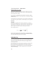
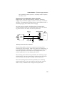
COMMAND INPUT
The OEM670T/OEM675T monitors an analog voltage signal,
called command input, at its input terminals (Command + and
Command –). It sends an output current to the motor that is
31
➁ Installation • OEM670/OEM675
proportional to the command input signal. Your controller’s
command voltage can range from -10VDC to +10VDC.
The OEM670T/OEM675T will produce 1.2 amps for each volt
present at its input terminals. A 10 volt command input will
result in peak current (12A) flowing to the motor. Smaller
voltages result in proportionally less current, with a Ø volt
command input resulting in no current to the motor.
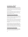
Positive voltages cause the OEM670T/OEM675T to produce
currents that turn the motor’s shaft clockwise. Negative
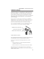
voltages cause currents that turn the shaft counterclockwise.
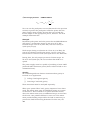
As the next drawing shows, shaft rotation is defined as the
direction the shaft rotates, as viewed from the mounting
flange end of the motor.
Clockwise Shaft Rotation
Connect your controller’s command output signal to the
OEM670T/OEM675T’s command input terminals, Pin 1 and
Pin 2, as described in the following sections.
32
OEM670/OEM675 • ➁ Installation
Controller with Single-Ended Output
If your controller uses a single-ended output—a single terminal that produces a voltage ranging from -10VDC to
+10VDC—connect that output to Command Plus (Pin 1) on
the OEM670T/OEM675T.
Connect wires from the OEM670T/OEM675T’s Command
Minus and Ground terminals to the controller’s ground terminal. If you connect the wires as shown in the next drawing,
you will minimize electrical noise in the circuit.
OEM670T/OEM675T Internal Connections
Controller
10KΩ
Command Out
(-10VDC to +10VDC)
CMD +
Command GND
CMD -
GND
GND
10KΩ
1
2
16
10KΩ
10KΩ
Controller—Single-Ended Output Connections
Bring both wires from the OEM670T/OEM675T to the controller, and connect them both to the controller. This will ensure
that the OEM670T/OEM675T’s Command Minus input and
Ground input are both referenced to the controller’s ground
terminal.
Controller with Differential Output
If your controller has a differential output, then it has two
command signals. One is a signal that ranges from -5VDC to
+5VDC. The other signal ranges from +5VDC to -5VDC. The
two signals mirror each other—their magnitudes are equal,
but they have opposite signs.
Your controller should also have a ground terminal to use as
a reference for the positive and negative command outputs.
33
➁ Installation • OEM670/OEM675
OEM670T/OEM675T
Controller
Internal Connections
10KΩ
+ Command Out
CMD +
- Command Out
CMD -
10KΩ
1
2
16
Command GND
10KΩ
10KΩ
GND
Controller—Differential Output Connections
The figure above shows how to connect these three outputs to
the OEM670T/OEM675T.
Controller with Isolated Output
Some controllers have isolated command outputs, and may
require a voltage source to power their outputs. The
OEM670T/OEM675T has three pins available to power isolated outputs on a controller. These pins provide:
❏ +15VDC
❏ -15VDC
❏ GROUND
on Pin 14
on Pin 15
on Pin 16
The next figure shows a typical controller with isolated differential outputs, and illustrates how you can connect it to the
OEM670T/OEM675T.
OEM670T/OEM675T
Controller
+15VDC In
Internal Connections
+15VDC
10KΩ
Isolated
Output
Circuitry
10KΩ
+ Command Out
CMD +
1
- Command Out
CMD -
2
14
15
-15VDC In
GND
-15VDC
GND
16
10KΩ
10KΩ
Controller—Isolated Output Connections
If your controller has an isolated single-ended output, connect
34
OEM670/OEM675 • ➁ Installation
the ±15VDC outputs as shown in this figure. Connect the
command and ground signals as shown earlier in the section
on single-ended outputs.
ENABLE INPUT
When the enable input of the OEM670T/OEM675T is connected to ground, the OEM670T/OEM675T is enabled, and
will function normally. To disable the OEM670T/OEM675T,
break the connection to ground, or connect the enable input
to +5VDC.
WARNING
Dangerous conditions can result if the enable input is not connected to a
suitable controller output. Many controllers produce uncontrolled command
output voltages during power up, power down, fault, or reset conditions.
Unpredictable and potentially dangerous machine movement may occur if
the OEM670T/OEM675T’s enable input is not properly connected.
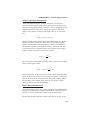
The next figure shows how to connect a controller with an
open collector enable output to the OEM670T/OEM675T.
When the transistor in the controller is on, the controller’s
enable output is effectively tied to ground. This grounds the
OEM670T/OEM675T’s enable input, and the OEM670T/
OEM675T is enabled.
Controller
Manual Disable
(normally closed)
OEM670T/
OEM675T
Internal Connections
+5V
2.49KΩ
Enable Out
ENABLE IN
10
11
Ground
GND
22KΩ
22KΩ
Enable Input Connected to a Controller
This figure also shows an optional switch that can be used as
a manual disable switch. The switch is normally closed. When
it is opened, the drive will be disabled.
35
➁ Installation • OEM670/OEM675
As the next figure shows, the OEM670T/OEM675T could also
be enabled simply by closing a switch that connects its enable
input to ground.
OEM670T/OEM675T
Internal Connections
+5V
2.49KΩ
ENABLE IN
Enable Out
10
11
Ground
22KΩ
GND
22KΩ
Enable Input Connected to a Switch
Connecting a jumper between the OEM670T/OEM675T’s
enable input and ground is a quick way to temporarily enable
the OEM670T/OEM675T. You may wish to do this, for example, if you need to test the OEM670T/OEM675T when it is
not connected to a controller. Enabling the drive in this
manner may be dangerous, however—see the warning above.
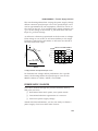
FAULT OUTPUT
When the OEM670T/OEM675T is operating normally, its fault
output is low. Under these conditions, an internal transistor
acts as a switch, and grounds the fault output. To signal a
fault, the OEM670T/OEM675T will turn off the transistor,
and the fault output will float. The next drawing shows this
circuit.
+5VDC to +24VDC
Controller
Pull-up
Resistor
Fault Input
Internal
OEM670T/ Connections
OEM675T
ON = Normal
OFF = Fault
FAULT OUTPUT
(Can sink 20 mA)
Fault Output
36
9
OEM670/OEM675 • ➁ Installation
Use a pull-up resistor connected to a DC voltage source to
ensure the appropriate signal level at your controller’s fault
input. The OEM670T/OEM675T can sink 20 mA maximum.
Use the following formula to calculate the value of your pullup resistor.
Rpull-up = VS / 5 mA
where
VS is the value of your DC voltage source.
You can use the OEM670T/OEM675T’s fault output as a
signal to your controller that a fault has occurred. The following conditions will cause the fault output to go high.
Condition
Drive Not Enabled
Over Temperature
Overvoltage
Undervoltage
Short Circuit
Power Supply Fault
(Latched)
(Latched)
(Latched)
(Latched)
LED Status
RED
GREEN
On
On
On
On
On
On
On
On
On
OFF
On
OFF
The foldback circuit illuminates the red LED, but it does not
make the fault output go high.
Latched means you must cycle power before the drive will
operate again.
CURRENT MONITOR
You can use the OEM670T/OEM675T’s current monitor
output to measure motor current. Connect pin 25 to the
positive input of your oscilloscope, meter, etc. Use pin 24 as a
signal ground for your oscilloscope or meter.
The OEM670T/OEM675T monitors the actual motor current.
It puts out a voltage on pin 25 that is proportional to current,
with 1 volt out = 1.2 amps of motor current. Positive voltages
correspond to clockwise rotation (as viewed from the mounting flange end of the motor). Negative voltages correspond to
counterclockwise rotation.
37
➁ Installation • OEM670/OEM675
Oscilloscope, Meter,
Controller, Etc.
Internal
Connections
OEM670/OEM675
Current Monitor IN +
24
25
Current Monitor +
10KΩ
IN -
Current Monitor Output Connections
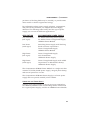
GROUND PINS – ANALOG AND DIGITAL
The OEM670T/OEM675T has four ground pins, located at
pins 7, 11, 16, and 24. For noise-sensitive circuits, such as
command input and current monitor output, use the “analog”
ground pins, 16 and 24. For digital circuits, such as the
enable input or the fault output, use the “digital” ground pins,
7 and 11.
Why the distinction? The analog grounds are for use with
signals where electrical noise should be kept to a minimum.
Digital circuits can be quite noisy. If a clean analog ground is
connected to a noisy digital ground, some of the noise from
the digital circuit may be coupled into the analog circuit.
The four grounds are eventually connected together inside the
OEM670T/OEM675T, but there are features in the internal
circuitry that keep noise in digital circuits from entering
sensitive analog circuits. So, for noise sensitive signals, use
the analog grounds.
38
Type of Ground
Analog Ground
Pin #
16
24
Intended Use
Command Input
Current Monitor
Digital Ground
11
7
Enable Input
Fault Output, or
Misc. Digital Circuitry
OEM670/OEM675 • ➁ Installation
OEM670SD/OEM675SD INPUTS AND OUTPUTS
Note: This section describes inputs and outputs for the
OEM670SD and OEM675SD. See the previous section for
OEM670T and OEM675T input/output descriptions.
You must connect step and direction, enable, and encoder
signals to the OEM670SD/OEM675SD for it to work. Connections are described below under Required Inputs. Use the
drive’s other inputs and outputs, described under Optional
Inputs and Outputs, for your application’s specific requirements.
CLOCKWISE AND COUNTERCLOCKWISE – DEFINITIONS
Shaft rotation is defined as the direction the shaft rotates,
when viewed from the mounting flange end of the motor. (See
the drawing several pages earlier, which illustrates the clockwise direction.)
Unlike a step motor system, which operates open loop, the
OEM670SD/OEM675SD is a closed loop servo system. It
requires feedback from the encoder for stability. For each step
pulse received while Direction+ is positive, the drive will make
the motor turn in the positive direction a distance of one
positive encoder count. For stability, it is important that you
connect your system so that a positive step command causes
the encoder position to increment, not decrement.
If the system is connected incorrectly, each step pulse will
cause the encoder to move in the wrong direction, causing
increasing position errors. This could lead to instability and a
motor runaway, in which the motor spins faster and faster,
eventually going out of control.
39
➁ Installation • OEM670/OEM675
OEM
series
Velocity Monitor
1
CPE2 (Position Error)
2
Step+
3
Direction+
4
Derivative Gain Reduction 5
R
&DI EC
NSE
TIO
E STEP
Compumotor
O DRIV
RV
POWER
FAULT
VDC+
VDCHALL GND
HALL +5V
HALL 1
HALL 2
HALL 3
PHASE A
PHASE B
PHASE C
Integral Gain Disable
6
Ground
7
CPE1 (Position Error)
8
Fault (not isolated)
9
Enable
10
Ground
11
Shutdown+
12
Shutdown–
13
14 Step15 Direction16 Encoder GND
17 Encoder +5V
18 Encoder A+
19 Encoder A20 Encoder B+
21 Encoder B22 Fault+ (isolated)
23 Fault– (isolated)
24 Current Monitor25 Current Monitor+
OEM670SD/OEM675SD Inputs & Outputs, and Internal Connections
REQUIRED INPUTS
Step & Direction Inputs
Connect your indexer to the step and direction inputs, as
shown in the next drawing. These inputs are optically isolated. For best performance, your indexer should drive the
inputs differentially. Single-ended operation is also possible,
especially at lower step frequencies (where the diode switching
speed is not as critical).
OEM670SD/
OEM675SD
Indexer
Internal Connections
+5V
Step– 14
464Ω
464Ω
Step+ 3
1
14
Direction– 15
2
+5V
15
HCPL2631
3
Direction+ 4
4
464Ω
464Ω
HCPL2631
Step & Direction Inputs
Specifications for the step and direction inputs are as follows:
40
OEM670/OEM675 • ➁ Installation
Specifications
Applied Voltage
Input Current
Step+/Step–
Dir+/Dir–
5 V maximum
(pins 3 & 14)
(pins 4 & 15)
12 mA maximum
6.3 mA minimum
Step Pulse
500 nsec minimum pulse width
Setup Time
Direction input may change polarity coincident
with the last step pulse. The direction input
must be stable for 500 nsec before the drive
receives the first step pulse.
You can use an input voltage higher than 5V if you install a
resistor, in series with the input, to limit current to the range
specified above.
Enable Input
You must connect the enable input to ground before you
power up the drive, in order for the drive to be enabled. This
input is internally pulled up to +5V. If you break the connection to ground while the drive is on, the OEM670SD/
OEM675SD’s fault circuitry will activate with these results:
❏
❏
❏
❏
The drive will shut down power output to the motor.
The motor will freewheel (it may not stop immediately).
The red Fault LED will be illuminated.
The fault output will become active (no current will flow
through it).
To reset the drive, reestablish the connection between enable
and ground, and cycle power.
In most applications, you can permanently wire the enable
input to ground. If you need to disable the drive during normal operations, you should use the shutdown input—it allows
you to re-enable the drive from the indexer without cycling
power. The shutdown input is described later in this section.
If you need to disable the drive in an emergency, use the
enable input—not the shutdown input. Connect a manual
disable switch to the enable input, as the next drawing shows.
The switch is normally closed. When it is opened, the drive
will be disabled. The load can freewheel—therefore, you
should use a brake to stop the motor immediately in applications where a freewheeling motor can cause injury or damage.
41
➁ Installation • OEM670/OEM675
OEM670SD/
OEM675SD
Manual Disable
(normally closed)
Internal Connections
+5V
2.49KΩ
Enable
10
11
22KΩ
Ground
22KΩ
Enable Input Connected to a Switch
WARNING
Do not use the ENABLE INPUT by itself as an emergency stop. The motor
can freewheel when the drive is disabled and may not stop immediately. Use
a mechanical brake or some other method to stop the motor quickly.
Encoder Input Connections
You must connect an encoder to the OEM670SD/
OEM675SD's encoder inputs. These are differential inputs;
therefore, your encoder should have differential outputs.
Single-ended operation is possible, but is more susceptible to
electrical noise and is not recommended. If you use an OEM
Series motor, see Specifications: Encoder in Chapter ➂ Specifications for the pinout of the encoder connector. Up to 200 mA
at 5 volts is available on pin 17 to power encoder electronics.
Motor
OEM670SD/
OEM675SD
14
Internal Connections
200mA max. at 5V available on
pin 17 to power encoder electronics
15
MOTOR
Encoder
Encoder Ground
+5V (to encoder)
A+
AB+
B-
+5V
16
17
18
19
681Ω
681Ω
B+
20
21
B-
• Maximum low input: 0.8V
• Minimum high input: 2.0V
• Maximum input frequency: 1 MHz
• A Leads B – CW Rotation
• B Leads A – CCW Rotation
Encoder Input
42
26LS32
681Ω
Internal Connections for CHA (18,19)
and CHB (20,21) are identical
OEM670/OEM675 • ➁ Installation
OPTIONAL INPUTS AND OUTPUTS
Connect any of the optional inputs and outputs that your
application requires. Each is described below.
Shutdown Input
Use the isolated shutdown input on pins 12 and 13 if you
need to temporarily disable the drive during normal operations. You may wish to do this, for example, to manually move
the load to a desired position. Make connections according to
the following diagram. The inputs are designed for 5V operation. You can use higher voltages if you connect an external
resistor in series with Shutdown+ to limit the input current.
Indexer,
Switch, etc.
OEM670SD/
OEM675SD
Applied Voltage: 5 V maximum
Input Current: 12 mA maximum
6.3 mA mininum
+5V
221Ω
11
Shutdown+
Internal Connections
1.6MΩ
0.33µF
12
13
Shutdown–
Shutdown Input
When +5V is applied to the Shutdown+ input, the
OEM670SD/OEM675SD's power output stage remains active,
but its internal controller commands zero torque. This allows
the motor shaft to be manually positioned. The controller will
ignore encoder counts and position error as the shaft turns.
Approximately one second after the shutdown input is released, the internal controller accepts the new position as the
commanded position, and reestablishes servo action.
While the OEM670SD/OEM675SD is in shutdown, it's small
internal offset torque will be applied to the load. This torque is
usually too low to overcome friction and cause motion. In
some applications, however, the shaft may need to be held in
the desired position during shutdown.
Note that shutdown in the OEM670SD/OEM675SD functions
differently than shutdown in a step motor drive. When a step
43
➁ Installation • OEM670/OEM675
motor drive is shut down, it actually shuts down its power
output stage. When it comes out of shutdown, the step motor
drive will command phase currents that immediately apply
torque to the shaft, which holds it in some position between
the poles.
CPE1 and CPE2 – Position Error Inputs
You can configure position error (CPE) with two position error
inputs, CPE1 and CPE2, on pins 8 and 2 respectively. Position
error faults provide warnings of impending problems such as
increased friction, or of immediate problems such as a mechanical jam. Position error is measured in post-quadrature
encoder counts. Four settings are available, as the next table
shows.
OEM670SD/OEM675SD
Internal Connections
+5V
681Ω
1
CPE2
2
3
26LS32
4
5
6
681Ω
7
CPE1
8
26LS32
CPE1 and CPE2 – Position Error Inputs
Number of Revolutions
Position Error Settings
500 Line
1000 Line
CPE1 CPE2
Error*
Encoder
Encoder
low
low
2047
1.024
0.512
high
low
4095
2.048
1.024
low
high
8191
4.096
2.048
(default) high
high
16383
8.196
4.096
high = not connected
low = connected to ground
*error is measured in post-quadrature encoder counts
When the OEM670SD/OEM675SD ships from the factory,
neither CPE1 nor CPE2 is connected to ground. This is the
44
OEM670/OEM675 • ➁ Installation
default setting; it selects the widest position error range. You
might begin with this setting when you start configuring your
system. This will give you the widest range of motion. Once
your system is tuned and performing properly, you can select
one of the other three settings by connecting either or both of
the inputs to ground.
The position error feature works as follows. Internally, the
drive generates a control voltage proportional to the difference
between the number of step pulses received and the number
of post-quadrature encoder counts received. The first 2047
counts in each direction produce an increasing error voltage.
This creates an increasing torque to move the load towards
the commanded position. After the first 2047 counts, maximum torque is being commanded. Additional error counts
have no immediate effect on torque, but they are accumulated
until the error is reduced by shaft motion, or the CPE limit is
reached. Reaching the limit causes a fault that disables the
drive and illuminates the red LED. You can clear the fault by
cycling power. Or, you can use the shutdown input to reset
the drive—this will clear the position error fault.
Velocity Monitor Output
A velocity monitor is available on pin 1. Its output is a voltage
signal proportional to encoder speed. You can connect a
voltmeter to the output to measure velocity, or you can connect an oscilloscope to help you tune your system. See the
Tuning section at the end of this chapter for more information.
The signal is always positive, regardless of the direction of
encoder rotation. It is scaled so that a pre-quadrature encoder
count frequency of 10 kHz produces an output of one volt.
The maximum output is +10V. (For example, a 1000 line
encoder rotating at 100 rps (100 kHz) will produce the maximum signal of +10V. The same encoder at 10 rps will produce
a signal of +1V.)
Encoder counts come slowly at low velocities, which can
cause the velocity monitor to show ripple at four times the line
frequency, resulting in a “fat” trace on the oscilloscope.
The next drawing shows typical connections to the velocity
monitor. Use pin 24 as a ground reference for your signal.
45
➁ Installation • OEM670/OEM675
Oscilloscope, Meter, etc.
OEM670SD
OEM675SD
Internal Connections
1
Velocity Monitor
Signal Scaling: 1V per 10 kHz
encoder frequency
(pre-quadrature)
Range: 0V to +10V max
(always positive)
Load: 2 KΩ min load
2
3
IN +
23
Monitor Reference
IN -
24
25
Velocity Monitor Output Connections
Derivative Gain Reduction – Input
This input (pin 5) can affect the derivative gain in the
OEM670SD/OEM675SD’s internal feedback loop. If no connections are made to the input, it leaves the gain unchanged.
If the input is connected to ground, the drive gradually reduces derivative gain to a low value whenever motion stops.
When commanded motion starts again, or if the motor shaft
moves, the drive instantly increases derivative gain to the
value set by the derivative tuning pot. See the Tuning section
at the end of this chapter for more information. The internal
schematic for the input is shown in the next drawing.
OEM670SD/OEM675SD
Internal Connections
+5V
1
2
3
10KΩ
10KΩ
4
Derivative Gain Reduction
Integral Gain Disable
Ground
5
6
26LS32
7
8
26LS32
Derivative Gain Reduction & Integral Gain Disable Inputs
46
OEM670/OEM675 • ➁ Installation
Integral Gain Disable – Input
This input (pin 6) can disable the integral gain in the
OEM670SD/OEM675SD’s internal feedback loop. If this input
is grounded, integral gain is disabled. If it is not grounded,
integral gain is determined by the tuning pot setting. We
recommend disabling integral gain by grounding pin 6, as an
initial setting to simplify tuning. You can add integral gain
later, if necessary. The internal schematic for the input is
shown above. See the Tuning section at the end of this chapter
for more information.
Fault Output – Isolated and Non-Isolated
The OEM670SD/OEM675SD has two fault output signals.
One is isolated (pins 22 and 23); the other is not isolated (pin
9). We recommend that you use the isolated fault output if
you need a fault signal for your system. The schematic and
specifications are:
OEM670SD/OEM675SD
Internal Connections
+5V
Fault Output
Not Isolated
221Ω
9
22
Isolated
23
24
Fault Output+
Fault Output–
25
ILD2
Fault Output – Isolated and Non-Isolated
Specifications
Maximum Applied Voltage
Maximum Current
Active Level
Isolated
Non-Isolated
Fault Output
Fault Output
(pin 22 & 23)
(pin 9)
50 V
24 V
10 mA
20 mA
No Fault: Transistor on, current flows
Fault: Transistor off, no current flows
When the OEM670SD/OEM675SD is operating normally,
each fault output’s internal transistor is in the “on” state, and
conducts current. If the OEM670SD/OEM675SD detects a
fault, it turns off the transistors, and current stops flowing.
47
➁ Installation • OEM670/OEM675
You can use the OEM670SD/OEM675SD’s fault output as a
signal to an indexer or PLC that a fault has occurred. The
following conditions will activate the fault output.
LED Status
Red
Green
Fault Condition
Drive Not Enabled
Over Temperature
Overvoltage
Undervoltage
Excess Position Error
Short Circuit
Power Supply Fault
Foldback
(latched)
(latched)
(latched)
(latched)
(latched)
(latched)
On
On
On
On
On
On
On
On
On
On
On
On
Off
Off
Foldback is not a fault; the red LED is
ON during foldback, but the fault
output is not activated.
Latched means you must cycle power before the drive will
operate again. You can also use the shutdown input to clear
position error faults, and to clear some undervoltage faults.
Current Monitor
The OEM670SD/OEM675SD’s current monitor output is
identical to the OEM670T/OEM675T’s current monitor output. See the current monitor description in the previous
section, OEM670T/OEM675T Inputs and Outputs, for more
information.
CONNECTING A POWER SUPPLY
The OEM670/OEM675 requires a single external power
supply with these features:
❏ 24VDC to 75VDC
❏ Fast Transient Response (can quickly supply enough
current to meet your application's requirements)
❏ Power Dump (not required for all applications)
The power dump may be required if your system produces
excess regenerated energy. To avoid damage, dissipate the
regenerated energy in a power resistor, store it in extra ca48
OEM670/OEM675 • ➁ Installation
pacitance (a blocking diode may be needed), or provide some
other means to absorb regenerated energy.
For information about power supply selection, regeneration,
and power dump methods, see Chapter ➅ Power Supply
Selection. The following table briefly lists the type of power
supply you can use for different applications.
APPLICATION
Very Low Power
(low regen)
RECOMMENDED POWER SUPPLY
24-48VDC Switching Power Supply
24-48VDC Linear Unregulated Supply
OEM300 Power Module
Low Power
(with regen)
Switching Power Supply with blocking
diode and extra capacitance.
Linear Unregulated Supply
OEM300 Power Module
High Power
(low regen)
Linear Unregulated Supply
with Transformer
OEM1000 Power Supply
High Power
(with regen)
Linear Unregulated Supply with added
Capacitance or added Power Dump
OEM1000 Power Supply
The Compumotor OEM300 Power Module is a single unit that
contains a 75VDC/300W power supply, integral power dump,
and several protective circuits.
The Compumotor OEM1000 Power Supply is a linear power
supply that can provide 1000W/15A at 70VDC.
CONNECTING THE POWER SUPPLY
Connect your power supply to the 10 pin screw terminal on
the OEM670/OEM675. The next drawing shows connections
for a typical power supply, and for an OEM300 Power Module.
49
➁ Installation • OEM670/OEM675
OEM300
POWER
MODULE
(RESERVED)
GND
+75VDC @ 2.7A
GND
POWER
TYPICAL
POWER
SUPPLY
POWER
FAULT
VDC+
VDCHALL GND
HALL +5
HALL 1
HALL 2
HALL 3
PHASE A
PHASE B
PHASE C
VDC+
GND
POWER
FAULT
VDC+
VDCHALL GND
HALL +5
HALL 1
HALL 2
HALL 3
PHASE A
PHASE B
PHASE C
Power Supply Connections
❏ Connect the positive DC terminal of your power supply
to the VDC+ input on the OEM670/OEM675’s 10-pin
screw terminal.
❏ Connect the ground terminal of your power supply to
VDC- on the OEM670/OEM675.
To reduce electrical noise, minimize the length of the power
supply wires and twist them tightly together.
Grounding
Internally, the Hall Ground and the grounds on the 25 pin Dconnector (pins 7, 11, 16, 24) are connected to VDC-. Do not
connect your power supply’s ground to these pins, however.
Connect it only to VDC-.
The shell of the 25 pin D-connector and the heatplate are
connected internally. They are not connected to VDC-, Hall
Ground, or the D-connector grounds (pins 7, 11, 16, 24).
Wire size
Use 18 AWG (0.75 mm2) or greater diameter wire for power
connections. For applications that use high peak power, use
larger diameter wires. 14 AWG (2.5 mm2) wire is the biggest
wire that will fit in the 10-pin screw terminal.
50
OEM670/OEM675 • ➁ Installation
Tuning – OEM670T/OEM675T Torque Drive
The OEM670T/OEM675T Torque Drive requires no tuning
adjustments. See your controller’s user guide for instructions
on controller tuning adjustments.
Tuning – OEM670SD/OEM675SD Step & Direction Drive
You must tune the OEM670SD/OEM675SD’s internal Proportional Integral Derivative (PID) servo control loop for optimum
system performance. A properly tuned system will exhibit
smooth motor rotation, accurate tracking, and fast settling
time.
TUNING THEORY
The OEM670SD/OEM675SD generates a move profile based
on step and direction signals from the indexer. Incoming steps
represent commanded position, and go to a summing node.
Incoming encoder counts represent actual position, and also
go to the summing node. During a move, actual position will
differ from commanded position by at least several encoder
counts. Actual position is subtracted from commanded position at the summing node—the resulting difference is the
position error, which is converted into an analog voltage. This
analog error signal is the input to the PID control loop, whose
block diagram is shown below.
Proportional
Gain Adjust
Integral
Gain
Disable
(pin 6)
Integral
Gain Adjust
KI
RI
Error
Signal
from DAC
+
KP
(fixed)
Loop Gain
+
Σ
Torque
Command
+
KD
Derivative
Gain Adjust
PID Control Loop – Block Diagram
Gain Reduction
Control Circuit
Derivative
Gain
Reduction
(pin 5)
51
➁ Installation • OEM670/OEM675
You can adjust three potentiometers (pots) to tune the PID
loop. These pots control the settings for proportional gain,
integral gain, and derivative gain. You have two other options:
you can connect pin 5 to ground to reduce derivative gain;
and you can connect pin 6 to ground to disable integral gain.
Each tuning parameter is described in the following sections.
Proportional Gain
Proportional gain provides a torque that is directly proportional to the magnitude of the error signal. Proportional gain is
similar to a spring—the larger the error, the larger the restoring force. It determines the stiffness of the system and affects
the following error. High proportional gain gives a stiff, responsive system, but can result in overshoot and oscillation.
Damping—provided by derivative gain—can reduce this
overshoot and oscillation.
Notice from the block diagram that adjusting proportional
gain affects the loop gain. This means that integral gain and
derivative gain are both affected by changes in the proportional gain tuning pot. This arrangement simplifies tuning;
once you set the integral and derivative gains in the correct
ratio to proportional gain, you only need to adjust proportional gain—integral and derivative gain will follow.
Derivative Gain
Derivative gain provides a torque that is directly proportional
to the rate of change of the error signal. When the error’s
instantaneous rate of change, or derivative, increases, derivative gain also increases. Derivative gain opposes rapid
changes in velocity. It will dampen the resonance effects of
proportional gain. With higher derivative gain, you can use
higher proportional gain.
Derivative Gain Reduction (Grounding Pin 5)
Many applications require high derivative gain for proper
performance. High derivative gain, however, can cause jitter
and audible shaft noise when the motor is at rest. Many
applications have enough stiction that high derivative gain is
not necessary for stability when the system is at rest. If your
application must hold position with minimum jitter or noise,
connect pin 5 to ground (see the Inputs and Outputs section
earlier in this chapter). With this pin grounded, the drive will
52
OEM670/OEM675 • ➁ Installation
gradually reduce derivative gain to a low value whenever
motion stops. When motion starts again, or if the motor shaft
moves, the drive will instantly increase derivative gain to the
value set by the tuning pot.
Integral Gain
Integral gain provides a torque that is directly proportional to
the sum, over time, of the error signal—the integral of the
error. If the error persists, integral gain provides a restoring
force that grows larger with time. Integral gain can remove
steady state errors that are due to gravity or a constant static
torque. It can also correct velocity lag and following error in a
constant velocity system.
Too much integral gain can cause overshoot during acceleration and deceleration, which will increase settling time. You
should use only as much as your application requires; if your
application does not need any integral gain, you should
disable it by grounding pin 6 (see below).
Integral Gain Disable (Grounding Pin 6)
You can permanently disable integral gain by wiring pin 6 to
ground. Notice on the block diagram that even if you zero the
integral gain pot, integral gain is not reduced to zero, just to a
lower value. There will still be integral gain in the system
(because of voltage on resistor RI). The only way you can
eliminate integral gain is to connect pin 6 to ground.
Or, you can use a control signal to temporarily disable integral
gain, by connecting pin 6 to ground only during acceleration
and deceleration. This will disable integral gain during those
parts of the move, which should decrease overshoot and
settling time. When the system reaches constant velocity or
comes to rest, use your control signal to break the ground
connection, which will re-enable integral gain.
TUNING PROCEDURE
In the procedure described below, you will systematically vary
the tuning pots until you achieve a move that meets your
requirements for accuracy and response time. For the best
results, make a consistent, repetitive move that is representative of your application.
53
➁ Installation • OEM670/OEM675
Access to the pots is through three holes in the top of the
drive’s plastic cover. The proportional gain pot is closest to the
front of the drive; the integral gain pot is in the middle; and
the derivative gain pot is closest to the heatsink. Turn the
pots clockwise to increase the gains.
e
tiv
l
va al
i
na
r
r
De teg ortio
In rop
P
Tuning Pots are 12 turn pots
To Zero:
turn pot 12 turns
counterclockwise
To Increase Gain:
turn pot clockwise
Factory Default Settings:
P: 3 turns clockwise
I : 0 turns clockwise
D: 4 1/2 turns clockwise
Tuning Pot Locations
➀ Disable Integral Gain (optional)
If you do not need integral gain in your application, wire
pin 6 to ground to permanently disable integral gain (see
above). If you do use integral gain, tuning will be simplified
if you disable it now, and re-enable it in Step ➆ below.
➁ Set up the Velocity Monitor (optional)
Connect an oscilloscope to the velocity monitor output on
pin 1 of the 25 pin D-connector, as described earlier in the
Inputs and Outputs section. You can tune without the
velocity monitor, but using it will clearly show how your
system responds when you adjust the tuning pots.
➂ Set Pots to their Default Values
The tuning pots were set at default values when the
OEM670SD/OEM675SD shipped from the factory. If yours
is a new unit, skip this step and proceed to step ➃. Otherwise, follow this procedure to return the settings to their
default values:
54
OEM670/OEM675 • ➁ Installation
1. Turn each pot 12 turns counterclockwise (zero each pot).
2. Turn the proportional gain pot 3 turns clockwise.
3. Leave the integral gain pot at zero.
4. Turn the derivative gain pot 41⁄2 turns clockwise.
These settings will provide a stable but “mushy” response
with most motors and light loads.
➃ Increase Proportional Gain
Increase proportional gain until the system oscillates or
becomes unstable, then decrease the gain until the system
returns to stability (at least 1⁄2 turn counterclockwise).
➄ Increase Derivative Gain
Increase derivative gain until the system oscillates or
becomes unstable, then decrease the gain until the system
returns to stability (at least 1⁄2 turn counterclockwise).
➅ Repeat Step ➃ and Step ➄
With the increased damping from step ➄, you should now
be able to increase proportional gain further. With higher
proportional gain, you may need higher derivative gain. So,
iteratively repeat steps ➃ and ➄ until your system is critically damped. In general, you will want values for proportional and derivative gain that are as high as possible,
without producing unacceptable motor vibrations, overshoot, or ringing.
➆ Adjust Integral Gain
If you need integral gain in your application, adjust it now.
You should set integral gain to the lowest value that will
correct following errors and static position errors, but not
increase overshoot or settling time. Adjusting integral gain
may require you to readjust the derivative and integral gain
pots. In a system without static torque loading, you may
wish to disable integral gain entirely (see ➀ above).
This completes the tuning procedure.
55
➁ Installation • OEM670/OEM675
56
OEM670/OEM675 • ➂ Specifications
C
H
A
P
T
E
R
➂
Specifications
Complete specifications for the OEM670/OEM675 Drive are
listed in the following pages.
Specifications are also listed for Compumotor SM and
NeoMetric Series servo motors, along with speed/torque
curves and dimensions for the motors.
The motors are described by the following numbering system:
SM
SM Series
Frame,
Magnet
Length
161
162
231
232
233
Winding
A
B
Feedback
1
D – 500 ppr encoder
1
E – 1,000 ppr encoder
H – Hall-effect only
R – resolver
1
2
3
4
N
NeoMetric
Series
Frame,
Magnet
Length
xxxy
xxx = flange dia.
070 for 70 mm
092 for 92 mm
y = magnet length
reference 1 to 4
Winding
Identifying
character
D, E, F, etc.
Shafting
Connections
Options
MS – military style
N – none
3
4
10 – 10' cable
V – shaft seal
3
25 – 25' cable
FL – 18" leads
TQ – TQ amp seriesibl
N – normal
F – flat
2
K – keyway
L – extended
includes Hall-effect
not available on size 16
cable is hare-wired
size 23 w/MS or TQ connectors—IP65
Feedback
2
D – 500 ppr encoder
E – 1,000 ppr encoder
H – Hall-effect only
R – resolver
Shafting
Connections
Options
N – normal
F – flat
K – keyway
FL
MS
TQ
1
PT
2
10
B – brake
N – none
V – IP65
W – IP67
bl
1
2
92 mm motors only
70 mm motors only
The motors are equipped with Hall effect outputs for commutation feedback. Each motor has an encoder for feedback to
the controller. The motors are available with NEMA flanges for
compatibility with standard X-Y stages and gear boxes.
Encoder specifications and pinouts are listed after the motor
specifications.
57
➂ Specifications • OEM670/OEM675
Specifications: OEM670T/OEM675T Torque Drive
OEM670T/OEM675T Torque Drive – Specifications
POWER INPUT
Voltage
Current
POWER OUTPUT—MOTOR
Peak Current
Continuous Current
Voltage
Peak Power
Continuous Power
Switching Frequency
Bandwidth
Transconductance
Commutation
Short Circuit Protected
24-75VDC
Ø-12 amps
12A (approx 2 sec maximum duration
at 45°C ambient temperature.
See Current Foldback for details)
6A
90VDC maximum
840W (1.1 hp) (@75V supply voltage)
420W (0.56 hp)
20 kHz
2 kHz typical (dependant on motor)
1 volt = 1.2 amp
120° Hall Effect Sensors for
Six-State Commutation Method,
or Brushed DC Motor
Yes
POWER OUTPUT—HALL EFFECT SENSORS
+5VDC ± 0.5VDC
Voltage
50 mA (maximum)
Current
NO
Short Circuit Protected
POWER OUTPUT—TO CONTROLLER OUTPUT STAGE
Voltage
+15VDC ± 1.5VDC
-15VDC ± 1.5VDC
10 mA maximum, each output
Current
NO
Short Circuit Protected
CONTROL INPUTS
Command Input
Enable Input
-10V to +10V analog voltage
1 volt input = 1.2 amp output
Active LOW: Ø-0.8V @ 2mA
When disabled: Internal 2.49 KΩ
pullup resistor to +5VDC
Low State
High State
Input Frequency
Ø-0.8V
Internal 1 KΩ pullup resistor to +5V
Ø-2 kHz maximum
HALL INPUTS
58
OEM670/OEM675 • ➂ Specifications
OEM670T/OEM675T Torque Drive – Specs. (contin.)
SIGNAL OUTPUTS
Fault Output
Current Monitor
LEDs
PROTECTIVE CIRCUITS
Short Circuit
Over Temperature
Overvoltage
Undervoltage
Current Foldback
MOTOR CHARACTERISTICS
Minimum Inductance
Minimum Resistance
Loop Gain Adjustment
Active HIGH: open collector output,
maximum volts = 24VDC
Inactive LOW: Ø-0.4VDC at Ø-20 mA
-10V to +10V analog voltage
Scale: 1V corresponds to 1.2A output
Output Impedance: 10 KΩ
GREEN: power
RED: various fault conditions
see Troubleshooting for details
Turns Off Outputs to Motor; Latched
55°C ± 5°C trip temperature; Latched
95V ± 5V trip voltage; Latched
21.5V maximum; not Latched
Configurable with 3 resistors
see Special Internal Circuits for details
50 µH (micro Henrys)
0.25 Ω
Configurable with one resistor
see Special Internal Circuits for details
TEMPERATURE
Minimum Temperature
Maximum Temperature
Max. Heatplate Temp
Package Dissipation
Ø°C (32°F)
45°C (113°F)
45°C (113°F)
Heatplate: 0 to 30W, depending on
motor current; P = (IAVG/12 A)30 W
Cover: 3 watts maximum
Power Connector
10 pin screw terminal
14 AWG (2.5 mm2) maximum wire size
25 Pin D-connector
5 x1.6x3.5 in (127x41x89 mm) approx.
see Chapter ➁Installation
12 ounces (0.35 kg)
MECHANICAL
Input/Output Connector
Size
Dimensions
Weight
59
➂ Specifications • OEM670/OEM675
Specifications:
OEM670SD/OEM675SD Step & Direction Drive
OEM670SD/OEM675SD Step & Direction Drive
POWER INPUT
Voltage
Current
POWER OUTPUT—MOTOR
Peak Current
Continuous Current
Voltage
Peak Power
Continuous Power
Switching Frequency
Bandwidth
Transconductance
Commutation
Short Circuit Protected
24-75VDC
Ø-12 amps
12A (approx 2 sec maximum duration
at 45°C ambient temperature.
See Current Foldback for details)
6A
90VDC maximum
840W (1.1 hp) (@75V supply voltage)
420W (0.56 hp)
20 kHz
2 kHz typical (dependant on motor)
1 volt = 1.2 amp
120° Hall Effect Sensors for
Six-State Commutation Method,
or Brushed DC Motor
Yes
POWER OUTPUT—HALL EFFECT SENSORS
Voltage
+5VDC ± 0.5VDC
Current
50 mA (maximum)
NO
Short Circuit Protected
POWER OUTPUT—TO ENCODER
Voltage
Current
Short Circuit Protected
CONTROL INPUTS
Step+/Step–
+5VDC
200 mA maximum, each output
NO
Direction+/Direction–
5V maximum input
Input current: 12 mA max., 6.3 mA min.
5V maximum input
Input current: 12 mA max., 6.3 mA min.
Pos. input = clockwise motor rotation
Low State
High State
Input Frequency
Ø-0.8V
Internal 1 KΩ pullup resistor to +5V
Ø-2 kHz maximum
HALL INPUTS
60
OEM670/OEM675 • ➂ Specifications
OEM670SD/OEM675SD Step & Direction Drive (contin.)
SIGNAL OUTPUTS
Fault Output-Isolated
Fault Output-Not Isolat.
Velocity Monitor
Current Monitor
LEDs
PROTECTIVE CIRCUITS
Short Circuit
Over Temperature
Overvoltage
Undervoltage
Current Foldback
Position Error
MOTOR CHARACTERISTICS
Minimum Inductance
Minimum Resistance
Loop Gain Adjustment
50V max voltage, 10 mA max current
24V max voltage, 20 mA max current
1V per 10 kHz pre-quad. encoder freq.
1V output per 1.2A motor current
Output Impedance: 10 KΩ
GREEN: power
RED: various fault conditions
see Troubleshooting for details
Turns Off Outputs to Motor; Latched
55°C ± 5°C trip temperature; Latched
95V ± 5V trip voltage; Latched
21.5V maximum; not Latched
Configurable with 3 resistors
see Special Internal Circuits for details
2047–16383 post-quad encoder counts
50 µH (micro Henrys)
0.25 Ω
Configurable with one resistor
see Special Internal Circuits for details
TEMPERATURE
Minimum Temperature
Maximum Temperature
Max. Heatplate Temp
Package Dissipation
Ø°C (32°F)
45°C (113°F)
45°C (113°F)
Heatplate: 0 to 30W, depending on
motor current; P = (IAVG/12 A)30 W
Cover: 3 watts maximum
Power Connector
10 pin screw terminal
14 AWG (2.5 mm2) maximum wire size
25 Pin D-connector
5 x 1.6 x 3.5 in (127 x 41 x 89 mm) approx.
see Chapter ➁Installation
14 ounces (0.4 kg)
MECHANICAL
Input/Output Connector
Size
Dimensions
Weight
61
➂ Specifications • OEM670/OEM675
Motor Specifications: SM160
Parameter
Symbol
Units
SM160A
SM160B
Stall Torque Continuous1
Tcs
lb-in/oz-in
0.88/14.1
0.89/14.2
N-m
0.10
0.10
Stall Current Continuous1
Ics
amperes-rms
2.6
5.1
Rated Speed2
ωr
rpm
7500
7500
Peak Torque1,6
Tpk
lb-in/oz-in
2.65/42.4
2.67/42.7
N-m
0.30
0.30
Peak Current, rms
1
Ipk
amperes
7.8
15.2
Torque @ Rated Speed1
Tc
lb-in/oz-in
0.66/10.5
0.66/10.5
N-m
0.075
0.075
Rated Power–Output Shaft1
Po
watts
58
58
3,4
Kb
volts/radian/sec
0.0384
0.0198
Voltage Constant3,4
Ke
volts/KRPM
4.02
2.08
Torque Constant3,4
Kt
oz-in/amp rms
5.43
2.81
N-m/amp rms
0.038
0.020
R
ohms
3.43
0.9
0.13
Voltage Constant
Resistance1,3
Inductance
5
L
millihenries
0.53
Thermal Resistance1
Rth
°C/watt
3.2
3.2
Motor Constant
Km
oz-in/√watt
2.93
2.96
N-m/√watt
0.021
0.021
oz-in/Krpm
0.267
0.267
N-m/Krpm
0.002
0.002
oz-in
1.0
1.0
N-m
0.007
0.007
Viscous Damping
Torque/Static Friction
B
Tf
Thermal Time Constant
τth
minutes
23
23
Electrical Time Constant
τe
milliseconds
0.16
0.15
Mechanical Time Constant
τm
milliseconds
0.73
0.72
Rotor Inertia
J
lb-in-sec 2
0.0000443
0.0000443
kg-m 2 x 10⁻⁶
5.0
5.0
Weight
#
pounds
0.72
0.72
kg
kilograms
0.327
0.327
H
H
Winding Class
1
2
3
4
5
6
@ 25°C ambient with 10 x 10 x 25 in. aluminum mounting plate, 90°C winding temperature. At 40°C
ambient, derate phase currents and torques by 12%.
With 500 ppr encoders. For 1,000 ppr encoders, derate to 6,000 rpm. For higher speed operation,
please contact factory.
±10% line-to-line
Peak value
±30%, line-to-line, inductance bridge measurement @ 1 kHz
Peak current for 1 second with initial winding temperature of 60°C or less.
All specifications are subject to engineering change.
62
OEM670/OEM675 • ➂ Specifications
Motor Specifications: SM161 and SM162
Parameter
Stall Torque Continuous1
Symbol
Units
SM161A
SM161B
SM162A
SM162B
Tcs
lb-in/oz-in
1.5/24
1.5/24
2.75/44
2.75/44
N-m
0.169
0.169
0.311
0.311
Stall Current Continuous1
Ics
amperes-rms
2.1
4.1
2.1
4.0
Rated Speed2
ωr
rpm
7,500
7,500
7,500
7,500
Peak Torque1,6
Tpk
lb-in/oz-in
4.5/72
4.5/72
8.25/132
8.25/132
N-m
0.509
0.509
0.933
0.933
Peak Current, rms
1
Ipk
amperes
10.5
20.5
10.5
20.0
Torque @ Rated Speed 1
Tc
lb-in/oz-in
1.25/20
1.25/20
2.56/41
2.56/41
N-m
0.141
0.141
0.290
0.290
Rated Power–Output Shaft1
Po
watts
110
110
222
227
3,4
Kb
volts/radian/sec
0.079
0.041
0.147
0.078
Voltage Constant3,4
Ke
volts/KRPM
8.27
4.29
15.39
8.17
Torque Constant3,4
Kt
oz-in/amp rms
11.18
5.8
20.8
11.05
N-m/amp rms
0.079
0.041
0.147
0.078
Resistance1,3
R
ohms
4.53
1.24
6.5
1.73
0.334
Voltage Constant
Inductance
5
L
millihenries
0.808
0.21
1.39
Thermal Resistance1
Rth
°C/watt
2.75
2.67
2.0
2.01
Motor Constant
Km
oz-in/√watt
5.36
5.26
8.66
8.36
N-m/√watt
0.038
0.037
0.061
0.059
oz-in/Krpm
0.257
0.171
0.234
0.276
N-m/Krpm
0.002
0.001
0.002
0.002
oz-in
1.0
1.0
1.1
1.1
N-m
0.007
0.007
0.007
0.007
Viscous Damping
Torque/Static Friction
B
Tf
Thermal Time Constant
τth
minutes
30
30
30
3.0
Electrical Time Constant
τe
milliseconds
0.178
0.169
0.21
0.193
Mechanical Time Constant
τm
milliseconds
9.2
9.4
5
6.2
Rotor Inertia
J
lb-in-sec 2
0.000094
0.000094
0.000163
0.000163
kg-m 2 x 10⁻⁶
10.6
10.6
18.4
18.4
Weight
#
pounds
1.1
1.1
1.6
1.6
kg
kilograms
0.50
0.50
0.73
0.73
H
H
H
H
Winding Class
1
2
3
4
5
6
@ 25°C ambient with 10 x 10 x 25 in. aluminum mounting plate, 90°C winding temperature. At 40°C
ambient, derate phase currents and torques by 12%.
With 500 ppr encoders. For 1,000 ppr encoders, derate to 6,000 rpm. For higher speed operation,
please contact factory.
±10% line-to-line
Peak value
±30%, line-to-line, inductance bridge measurement @ 1 kHz
Peak current for 1 second with initial winding temperature of 60°C or less.
All specifications are subject to engineering change.
63
➂ Specifications • OEM670/OEM675
Motor Specifications: SM230 and SM231
Parameter
Stall Torque Continuous1
Symbol
Units
SM230A
SM230B
SM231A
SM231B
Tcs
lb-in/oz-in
1.8/28.9
1.7/27.6
2.87/50
2.87/46
N-m
0.204
0.195
0.353
0.353
Stall Current Continuous1
Ics
amperes-rms
2.5
5.0
2.1
4.1
Rated Speed2
ωr
rpm
7500
7500
7,500
7,500
Peak Torque1,6
Tpk
lb-in/oz-in
5.4/87
5.2/83
8.61/150
8.61/150
N-m
0.615
0.587
1.060
1.060
Peak Current, rms
1
Ipk
amperes
7.5
15
10.5
20.5
Torque @ Rated Speed 1
Tc
lb-in/oz-in
1.5/24
1.4/23
2.37/38
2.25/36
N-m
0.170
0.163
0.269
0.254
Rated Power–Output Shaft1
Po
watts
134
127
205
205
3,4
Kb
volts/radian/sec
0.081
0.0391
0.169
0.079
Voltage Constant3,4
Ke
volts/KRPM
8.52
4.09
16.86
8.27
Torque Constant3,4
Kt
oz-in/amp rms
11.52
5.54
22.8
11.18
N-m/amp rms
0.081
0.039
0.161
0.079
Resistance1,3
R
ohms
4.43
1.12
5.22
1.46
Voltage Constant
Inductance
5
L
millihenries
1.19
0.28
1.64
0.44
Thermal Resistance1
Rth
°C/watt
2.67
2.67
2.23
1.86
Motor Constant
Km
oz-in/√watt
5.47
5.24
9.97
9.68
N-m/√watt
0.039
0.037
0.070
0.068
oz-in/Krpm
0.375
0.375
0.565
0.266
N-m/Krpm
0.003
0.003
0.004
0.002
oz-in
1.0
1.0
1.2
1.2
N-m
0.007
0.007
0.008
0.008
Viscous Damping
Torque/Static Friction
B
Tf
Thermal Time C onstant
τth
minutes
30
30
30
30
Electrical Time Constant
τe
milliseconds
0.27
0.25
0.31
0.3
Mechanical Time Constant
τm
milliseconds
16.97
18.51
13.7
14.5
Rotor Inertia
J
lb-in-sec 2
0.000224
0.000224
0.00046
0.00046
kg-m 2 x 10⁻⁶
25.3
25.3
52.0
52.0
Weight
#
pounds
1.2
1.2
2.6
2.6
kg
kilograms
0.54
0.54
1.18
1.18
H
H
H
H
Winding Class
1
2
3
4
5
6
@ 25°C ambient with 10 x 10 x 25 in. aluminum mounting plate, 90°C winding temperature. At 40°C
ambient, derate phase currents and torques by 12%.
With 500 ppr encoders. For 1,000 ppr encoders, derate to 6,000 rpm. For higher speed operation, please
contact factory.
±10% line-to-line
Peak value
±30%, line-to-line, inductance bridge measurement @ 1 kHz
Peak current for 1 second with initial winding temperature of 60°C or less.
All specifications are subject to engineering change.
64
OEM670/OEM675 • ➂ Specifications
Motor Specifications: SM232 and SM233
Parameter
Symbol
Units
SM232A
SM232B
SM233A
SM233B
Stall Torque Continuous1
Tcs
lb-in/oz-in
5.75/92
6.12/98
8.75/144
8.75/140
N-m
0.650
0.693
1.08
0.989
Stall Current Continuous1
Ics
amperes-rms
2.1
4.1
2.1
4.1
Rated Speed
ωr
rpm
4,500
7,5002
2,800
7,5002
Peak Torque1,6
Tpk
lb-in/oz-in
17.25/276
18.36/294
26.25/432
26.25/432
N-m
1.95
2.08
3.05
3.05
Peak Current, rms
1
Ipk
amperes
10.5
20.5
10.5
20.5
Torque @ Rated Speed1
Tc
lb-in/oz-in
4.87/78
5.12/82
8.37/134
7.12/114
N-m
0.551
0.580
0.947
0.806
Rated Power–Output Shaft1
Po
watts
260
450
277
505
3,4
Kb
volts/radian/sec
0.31
0.169
0.484
0.242
Voltage Constant3,4
Ke
volts/KRPM
32.45
17.69
50.6
25.33
Torque Constant3,4
Kt
oz-in/amp rms
43.89
23.91
68.53
34.23
N-m/amp rms
0.310
0.169
0.484
0.242
R
ohms
7.5
2.01
9.65
2.58
Voltage Constant
Resistance1,3
Inductance
5
L
millihenries
2.9
0.782
4.08
1.06
Thermal Resistance1
Rth
°C/watt
1.58
1.5
1.25
1.26
Motor Constant
Km
oz-in/√watt
15.99
16.86
22.00
21.25
N-m/√watt
0.113
0.119
0.155
0.150
oz-in/Krpm
0.525
0.328
0.778
0.459
N-m/Krpm
0.004
0.002
0.005
0.003
oz-in
2.0
2.0
2.25
2.25
N-m
0.014
0.014
0.016
0.016
Viscous Damping
Torque/Static Friction
B
Tf
Thermal Time C onstant
τth
minutes
35
35
40
40
Electrical Time Constant
τe
milliseconds
0.39
0.39
0.42
0.41
Mechanical Time Constant
τm
milliseconds
8.6
8.8
5.4
7.0
Rotor Inertia
J
lb-in-sec 2
0.00082
0.00082
0.00117
0.00117
kg-m 2 x 10⁻⁶
92.6
92.6
132.2
132.2
Weight
#
pounds
3.5
3.5
4.4
4.4
kg
kilograms
1.59
1.59
2.00
2.00
H
H
H
H
Winding Class
1
2
3
4
5
6
@ 25°C ambient with 10 x 10 x 25 in. aluminum mounting plate, 90°C winding temperature. At 40°C
ambient, derate phase currents and torques by 12%.
With 500 ppr encoders. For 1,000 ppr encoders, derate to 6,000 rpm. For higher speed operation, please
contact factory.
±10% line-to-line
Peak value
±30%, line-to-line, inductance bridge measurement @ 1 kHz
Peak current for 1 second with initial winding temperature of 60°C or less.
All specifications are subject to engineering change.
65
➂ Specifications • OEM670/OEM675
Motor Specifications: NeoMetric N0701 and N0702
Parameter
Symbol
Units
Winding Selection
N0701
N0702
or N0341
or N0342
D
F
Stall Torque Continuous1, 4
Tcs
lb-in
Stall Current Continuous1, 2
Ics
amperes-rms
2.92
4850
E
F
5.8
N-m
10.6
0.65
1.20
4.56
3.36
7500
3025
4.67
7
ωr
rpm
Peak Torque1
Tpk
lb-in
Peak Current, rms1, 6
Ipk
amperes
Tc
lb-in
4.6
4.7
8.6
8.6
N-m
0.52
0.53
0.97
0.97
Rated Speed
17.3
N-m
Torque @ Rated Speed
1
1.96
8.8
4380
32.0
3.62
13.7
10.1
14.0
Rated Power–Output Shaft1
Po
watts
265
415
309
447
Voltage Constant3, 4
Kb
volts/radian/sec
0.221
0.14
0.353
0.253
Voltage Constant3, 4
Ke
volts/KRPM
23.11
14.67
36.97
26.52
3, 4
Kt
lb-in/amp rms
1.95
1.24
3.12
2.24
N-m/amp rms
0.22
0.14
0.35
0.25
Torque Constant
Resistance3
R
ohms
5.52
2.27
5.22
2.7
Inductance5
L
millihenries
12.98
5.23
15.86
8.16
Thermal Resistance1
Rth
°C/watt
Motor Constant
Km
lb-in/√watt
0.83
0.82
1.37
N-m/√watt
0.09
0.09
0.15
Viscous Damping
B
Torque-Static Friction
Tf
1.44
1.15
1.36
0.15
lb-in/Krpm
0.0438
0.050
N-m/Krpm
0.0050
0.0056
oz-in
1.4
2.1
N-m
0.010
0.015
Thermal Time Constant
τth
minutes
45
45
Electrical Time Constant
τe
milliseconds
2.35
3.03
Mechanical Time Constant
τm
milliseconds
1.3
0.77
Rotor Inertia
J
lb-in-sec 2
0.000106
0.000173
kg-m 2 x 10⁻⁶
12.0
19.5
Weight
#
pounds
3.54
4.53
kg
kilograms
1.47
2.05
H
H
Winding Class
1
@ 25°C ambient with 10 x 10 x 0.25 in. aluminum mounting plate, 90°C encoder temperature.
2
RMS current, line-to-line, six state commutation
3
±10% line-to-line
4
Peak value
5
±30%, line-to-line, inductance bridge measurement @ 1 kHz
6
Peak current for 2 second maximum with initial winding temperature of 40°C
7
For “E”, encoder option, 1000 ppr, maximum velocity is 6000 RPM
All specifications are subject to engineering change.
66
OEM670/OEM675 • ➂ Specifications
Speed/Torque Curves2,3: SM 160, SM161 and SM162
(N-m) oz-in
(0.38) 50
SM160A with OEM670/OEM6751
(N-m) oz-in
(0.30) 40
(0.23) 30
(0.23) 30
Torque
Torque
(0.30) 40
(0.15) 20
0
(N-m) oz-in
(0.61) 80
2000
4000
6000
(33)
(67)
(100)
Speed – RPM (rps)
0
8000
(133)
SM161A with OEM670/OEM6751
Torque
Torque
(0.15) 20
0
3
2000
4000
6000
(33)
(67)
(100)
Speed – RPM (rps)
SM161B with OEM670/OEM6751
(0.30) 40
0
8000
(133)
SM162A with OEM670/OEM675
(0.95) 125
(0.95) 125
(0.76) 100
(0.76) 100
(0.57) 75
(0.38) 50
(0.19) 25
(0.19) 25
1000
(17)
2000
3000
4000
(33)
(50)
(67)
Speed – RPM (rps)
5000
(83)
2000
4000
6000
(33)
(67)
(100)
Speed – RPM (rps)
8000
(133)
SM162B with OEM670/OEM6751
(0.57) 75
(0.38) 50
0
0
(N-m) oz-in
(1.14) 150
Torque
Torque
2
8000
(133)
(0.15) 20
(N-m) oz-in
(1.14) 150
1
2000
4000
6000
(33)
(67)
(100)
Speed – RPM (rps)
(0.46) 60
(0.30) 40
0
0
(N-m) oz-in
(0.61) 80
(0.46) 60
0
(0.15) 20
(0.08) 10
(0.08) 10
0
SM160B with OEM670/OEM6751
0
0
2000
4000
6000
(33)
(67)
(100)
Speed – RPM (rps)
8000
(133)
For "E" encoder option (1000 ppr), maximum velocity is 6,000 rpm (100 rps).
With 75VDC bus voltage; 25°C (77°F) ambient temperature.
Although speed/torque curves are the same for the OEM670 and OEM675, the OEM670's current
compensation loop is optimized for NeoMetric (slotted) motors; the OEM675's current compensation loop is
optimized for SM (slotless) motors. We strongly recommend that you use the OEM670 with NeoMetric
motors, and use the OEM675 with SM motors. This provides the optimum system transient response.
67
➂ Specifications • OEM670/OEM675
Speed/Torque Curves2,3: SM230, SM231, SM232, SM233
(N-m) oz-in
(0.76) 100
SM230A with OEM670/OEM6751
(N-m) oz-in
(0.61) 80
(0.46) 60
(0.46) 60
Torque
Torque
(0.61) 80
(0.30) 40
0
0
8000
(133)
SM231A with OEM670/OEM675
(0.95) 125
(0.76) 100
(0.76) 100
(0.57) 75
(0.38) 50
(0.19) 25
(0.19) 25
(N-m) oz-in
(2.28) 300
1000
(17)
2000
3000
4000
(33)
(50)
(67)
Speed – RPM (rps)
0
5000
(83)
SM232A with OEM670/OEM675
(1.52) 200
Torque
(1.90) 250
(1.52) 200
(0.76) 100
(0.38) 50
(0.38) 50
0
(N-m) oz-in
(3.81) 500
500
(8)
1000
1500
2000
(17)
(25)
(33)
Speed – RPM (rps)
0
2500
(42)
SM233A with OEM670/OEM675
Torque
Torque
(1.52) 200
3
2000
4000
6000
(33)
(67)
(100)
Speed – RPM (rps)
8000
(133)
SM232B with OEM670/OEM675
1000
(17)
2000
3000
4000
(33)
(50)
(67)
Speed – RPM (rps)
5000
(83)
SM233B with OEM670/OEM675
(1.52) 200
(0.76) 100
(0.76) 100
2
SM231B with OEM670/OEM6751
(2.28) 300
(2.28) 300
0
0
(N-m) oz-in
(3.05) 400
(3.05) 400
8000
(133)
(1.14) 150
(0.76) 100
0
0
(N-m) oz-in
(2.28) 300
(1.90) 250
(1.14) 150
2000
4000
6000
(33)
(67)
(100)
Speed – RPM (rps)
(0.57) 75
(0.38) 50
0
0
(N-m) oz-in
(1.14) 150
(0.95) 125
0
Torque
2000
4000
6000
(33)
(67)
(100)
Speed – RPM (rps)
Torque
Torque
(N-m) oz-in
(1.14) 150
1
(0.30) 40
(0.15) 20
(0.15) 20
0
SM230B with OEM670/OEM6751
0
500
1000
1500
(5)
(10)
(15)
(20)
Speed – RPM (rps)
2000
(25)
0
0
500
(8)
1000 1500 2000 2500 3000
(17) (25) (33) (42) (50)
Speed – RPM (rps)
For "E" encoder option (1000 ppr), maximum velocity is 6,000 rpm (100 rps).
With 75VDC bus voltage; 25°C (77°F) ambient temperature.
Although speed/torque curves are the same for the OEM670 and OEM675, the OEM670's current
compensation loop is optimized for NeoMetric (slotted) motors; the OEM675's current compensation loop is
optimized for SM (slotless) motors. We strongly recommend that you use the OEM670 with NeoMetric
motors, and use the OEM675 with SM motors. This provides the optimum system transient response.
68
OEM670/OEM675 • ➂ Specifications
Speed/Torque Curves1,2: NeoMetric Motors
NO701D/NO341D with OEM670/OEM675
NO701F/NO341F with OEM670/OEM675
(N-m) oz-in
(2.28) 300
(N-m) oz-in
(1.90) 250
(1.90) 250
(1.52) 200
Torque
Torque
(1.52) 200
(1.14) 150
(0.76) 100
0
0
500 1000 1500 2000 2500 3000 3500
(8) (17) (25) (33) (42) (50) (58)
Speed – RPM (rps)
(3.05) 400
(3.05) 400
(2.28) 300
(2.28) 300
(1.52) 200
0
1000
(17)
2000
3000
4000
(33)
(50)
(67)
Speed – RPM (rps)
5000
(83)
NO702F/NO342F with OEM670/OEM675
(N-m) oz-in
(3.81) 500
(0.76) 100
2
0
(N-m) oz-in
(3.81) 500
Torque
Torque
NO702E/NO342E with OEM670/OEM675
1
(0.76) 100
(0.38) 50
(0.38) 50
0
(1.14) 150
(1.52) 200
(0.76) 100
0
500
(8)
1000
1500
2000
(17)
(25)
(33)
Speed – RPM (rps)
0
2500
(42)
0
500
(8)
1000 1500 2000 2500 3000
(17) (25) (33) (42) (50)
Speed – RPM (rps)
With 75VDC bus voltage; 25°C (77°F) ambient temperature.
Although speed/torque curves are the same for the OEM670 and OEM675, the OEM670's current
compensation loop is optimized for NeoMetric (slotted) motors; the OEM675's current compensation loop is
optimized for SM (slotless) motors. We strongly recommend that you use the OEM670 with NeoMetric
motors, and use the OEM675 with SM motors. This provides the optimum system transient response.
Motor Dimensions: Compumotor SM160 and SM230
SM160
SM230
(4x) Ø0.125 (3.175) thru holes
equally spaced on a
Ø1.838 (46.685) bolt circle
0.788 ± 0.001
(20.02 ± 0.025) 0.98
(24.89)
0.92
(23.37)
1.30 sq
(33.02)
1.60 sq
(40.64)
0.2500 + 0.0000
- 0.0005
(6.35 + 0.0000)
-0.0127)
2.87
(72.89)
1.97
(50.04)
0.37
(9.39)
Dimensions in inches
(millimeters)
0.78
(4x) Ø0.218 (5.537)
(19.81)
thru holes equally
spaced on a Ø2.625
(66.675) bolt circle 1.500 ± 0.001
(38.1 ± 0.025)
1.856 sq
(47.142)
2.24 sq
(56.9)
0.2500 + 0.0000
- 0.0005
(6.35 + 0.0000)
-0.0127)
0.34
(8.64)
0.71
(18.03)
2.01
(51.05)
2.91
(73.91)
69
➂ Specifications • OEM670/OEM675
Motor Dimensions: Compumotor SM Series, Size 16
Flying Leads
Cable Option
0.98 (24.89)
0.92 (23.37)
0.2500 + 0.0000
- 0.0005
(6.35 + 0.0000)
- 0.0127)
Ø0.788 ± 0.001
(20.02 ± 0.025)
0.37 (9.4)
1.30
(33.02) Sq.
1.60
(40.64) Sq.
(4x) Ø.125 thru holes equally
spaced on a Ø1.838 bolt circle
Motor Length
Cable Options
Part # Description
- FL 18" Flying Leads
10 ft. Cable
- 10
Longer lengths available
Consult Compumotor for information
Shaft Options
Ø0.250 (6.35)
-N
(None)
Dimensions in inches
(millimeters)
0.230 (5.842)
Motor Sizes
Motor Length Model
4.79 (121.66) 162 Motor
3.79 (96.27) 161 Motor
-F
(Flat)
Motor Dimensions: Compumotor SM Series, Size 23
Flying Leads
Cable Option
MS Connectors
Ø0.3750 + 0.0000
- 0.0005
(9.525 + 0.0000)
- 0.0127)
2.99
(75.95)
0.81 (20.57)
0.75 (19.05)
Ø1.500 ± 0.001
(38.1 ± 0.025)
Motor Length
1.856 (47.142) Sq.
2.25 (57.15) Sq.
(4x) Ø 0.218 (5.537)
thru holes equally spaced
on Ø2.625 (66.675) bolt circle
Dimensions in inches
(millimeters)
Shaft Options
Cable Options
Description
Part #
- FL 18" Flying Leads
10 ft. Cable
- 10
Longer lengths available
Consult Compumotor
for information
70
Ø0.375
(9.525)
0.340
(8.636)
0.60
(15.24)
Motor Sizes
0.94
(23.88)
1.25 (31.75)
1.19 (30.23)
0.416
(10.566)
-N
(None)
-F
(Flat)
-K
(Sq Key)
-L
(1.25 (31.75) Lg.)
Motor Length
Model
5.98 (151.89) 233 Motor
4.98 (126.49) 232 Motor
3.98 (101.09) 231 Motor
OEM670/OEM675 • ➂ Specifications
Motor Dimensions: NeoMetric Series, Size 70
Shaft Options
0.197
(5)
Ø0.43 (11)
- N (None)
MS Connectors Cable Flying Leads
-MS, -TQ
-10, -25
-FL
0.409 (10.4)
Dimensions in inches
(millimeters)
- F (Flat)
Motor Sizes
0.500
(12.7)
0.158
(4.01)
0.492 (12.49)
Feedback Conn
MS 14 - 18
- K (Sq. Key)
4 x Ø0.228 (5.8) Thru Holes
Eq Spaced on a Ø 2.953 (75.00)
Bolt Circle for 5mm or #10 Bolt
Brake Option -B
3.26
(82.8)
0.012)
(60 +
- 0.007)
Ø0.4331 + 0.003
- 0.001
(11.001 + 0.007)
- 0.002)
8.00 (203.20) 70-2 Brake
7.00 (177.80) 70-1 Brake
5.94 (150.88)
70-2
4.94 (125.48)
70-1
0.910 (23.1)
0.093 (2.36)
0.0005
Ø2.3622 +
- 0.0003
2.75
(69.85) Sq.
Motor Conn
MS 14 - 12
0.530
(13.46)
2.05
(52.1)
Motor Length
Motor Dimensions: NeoMetric Series, Size 34
MS Connectors Cable Flying Leads
-MS, -TQ
-10, -25
-FL
Shaft Options
0.228 (5.8)
0.473 (12.01)
Ø0.500 (12.7)
- N (None)
0.500
(12.7)
Dimensions in inches
(millimeters)
- F (Flat)
0.125
(3.175)
Feedback Conn
MS 14 - 18
0.56 (14.22)
Motor Conn
MS 14 - 12
- K (Sq. Key)
4 x Ø0.223 (5.66) Thru Holes
Eq Spaced on a Ø 3.875 (98.43)
Bolt Circle for 5mm or #10 Bolt
1.190 (30.23)
0.063 (1.6)
Ø2.875 ± 0.002
(73.03 ± 0.05)
3.25
(82.6) Sq.
Ø0.5000 + 0.0000
- 0.0005
(12.7 + 0.000)
- 0.012)
Motor Sizes
Motor Length
Model
8.00 (203.20) 34-2 Brake
7.00 (177.80) 34-1 Brake
5.94 (150.88)
34-2
4.94 (125.48)
34-1
Brake Option -B
3.26
(82.8)
0.250
(6.35)
2.05
(52.1)
Motor Length
71
➂ Specifications • OEM670/OEM675
Encoder Specifications
The same type of encoder is used on all SM and NeoMetric
Series motors. Encoders have either 500 lines ("-D") or 1000
lines ("-E).
Mechanical
Accuracy
±2 min of arc
Electrical
Input power
Operating frequency
Output device
Sink/Source, nominal
Suggested user interface
5 VDC ±5%, 135 mA
100 kHz max
26LS31
20 mA
26LS32
Hall Effect Specifications
Specifications for Hall effect outputs on SM and NeoMetric
Series motors are listed below.
Electrical
Input power
Output device, open collector
Maximum pull up
Sink
5 VDC ±5%, 80 mA
LM339
30 VDC
16 mA
COMMUTATION CHART
Clockwise rotation as viewed from front shaft.
Phase
B-A
Phase
A-C
Phase
C-B
Hall #1
Hall #2
Hall #3
72
OEM670/OEM675 • ➂ Specifications
Motor Wiring Information
SM MOTORS – SIZE 16 AND SIZE 23
Motor Phase
Designation
Phase A
Phase B
Phase C
Ground
Shield
Temp1
Temp1
-MS Option
Pin No.
MS14-12
-TQ Option
Pin No.
MS14-12
-H Option
Pin No.
MS14-12
-FL Option
-10 Option
-25 Option
Wire
Color
J
K
L
M
NC
G
H
J
K
L
M
NC
G
H
J
K
L
M
NC
G
H
Red/Yellow
White/Yellow
Black/Yellow
Green/Yellow
—
Yellow
Yellow
Pin No.
MS14-18
Pin No.
MS14-18
Not
Applicable
Wire
Color
H
G
A
B
C
D
E
F
NC
H
G
A
B
C
D
E
F
NC
—
—
—
—
—
—
—
—
—
Red
Black
White
Yellow
Green
Blue
Orange
Brown
—
Pin No.
MS14-18
Pin No.
MS14-12
Pin No.
MS14-12
Wire
Color
K
M
T
U
P
F
B
C
D
E
F
B
C
D
E
White/Green
White/Blue
White/Brown
White/Orange
White/Violet
Encoder
Designation
Vcc
Ground
CH A+
CH ACH B+
CH BIndex +
Index Shield
Hall-effect
Designation
Hall GND
Hall +5
Hall 1
Hall 2
Hall 3
Wiring color is provided for flying lead or cable versions.
73
➂ Specifications • OEM670/OEM675
NEOMETRIC MOTORS – SIZE 070 (SIZE 034)
Motor Phase
Designation
Pin No.
MS14-12
Phase A
Phase B
Phase C
Ground
Shield
J
K
L
M
NC
Continue for “H” or “TQ” Options
Temp
G
Temp
H
Hall GND
F
Hall +5
B
Hall 1
C
Hall 2
D
Hall 3
E
Wire Color
Red/Yellow
White/Yellow
Black/Yellow
Green/Yellow
—
Orange/Yellow
or Yellow (T)
White/Green
White/Blue
White/Brown
White/Orange
White/Violet
Encoder/Commutation Connections
Pin No.
MS14-18
Wire Color
Encoder
+5 VDC
Ground
CH A+
CH ACH B+
CH BIndex +
Index -
H
G
A
B
C
D
E
F
Red
Black
White
Yellow
Green
Blue
Orange
Brown
Commutation
Hall GND
Hall +5
Hall 1
Hall 2
Hall 3
Temp
Temp
K
M
T
U
P
L
N
White/Green
White/Blue
White/Brown
White/Orange
White/Violet
Orange/Yellow
or Yellow (T)
Brake Option
Brake
Brake
R
S
Red/Blue
Red/Blue
Designation
74
OEM670/OEM675 • ➃ Special Internal Circuits
C
H
A
P
T
E
R
➃
Special Internal Circuits
The OEM670/OEM675 has several internal circuits that can
protect the drive, protect equipment connected to the drive, or
change the drive’s performance characteristics.
Four of the built-in circuits work automatically. Their performance cannot be changed or altered.
❏ Short Circuit Protection
❏ Undervoltage
❏ Overvoltage
❏ Overtemperature
Two of the circuits use removable resistors in sockets. You
can change these resistors to alter the circuit parameters.
❏ Response Circuit
❏ Current Foldback Circuit
This chapter explains the performance of these circuits.
SHORT CIRCUIT PROTECTION
The OEM670/OEM675 continuously monitors the current it
sends to the motor. If it detects excessive current, it interprets
the excessive current as a short circuit fault in the motor or
cabling. The OEM670/OEM675 disables its power output to
the motor terminals—Phase A, Phase B, and Phase C.
To show that a short circuit fault has occurred, the drive
illuminates the red LED, turns off the green LED, and causes
the fault output (pin 9) to go high. Other power outputs—
Hall +5, +15VDC, -15VDC—remain on.
75
➃ Special Internal Circuits • OEM670/OEM675
The short circuit fault is a latched condition. Latched means
that the output will remain off until power is cycled. To cycle
power, turn off the power to the drive, wait approximately 30
seconds, then turn on the power.
The other power outputs (Hall +5, +15VDC, -15VDC) are not
short circuit protected.
Short circuit protection features are summarized below.
❏ Power to motor is turned OFF
❏ Red LED is turned ON
(Illuminated)
❏ Green LED is turned OFF (Not Illuminated)
❏ Fault output goes HIGH
❏ Latched
❏ Hall +5, +15VDC, -15VDC remain powered
❏ Hall +5, +15VDC, -15VDC are not short circuit protected
(Troubleshooting Note: Other faults will also turn on the red
LED, but they leave the green LED illuminated. Short circuit
protection is the only fault that will turn off the green LED
when it turns on the red LED.)
A short circuit fault is not the only event that can trigger this
circuit. A power supply fault can also trigger short circuit
protection. The fault can occur if the supply is undersized,
and cannot provide enough power during demanding move
profiles.
The next drawing shows graphs for motor current and power
supply voltage during a normal move profile.
76
OEM670/OEM675 • ➃ Special Internal Circuits
Normal Move Profile
Move Causing a Fault
Power
Supply
Voltage
Undervoltage
trips short circuit protection
Motor
Current
Drive Shuts
Down Motor
Current
Velocity
Time
Time
Power Supply Fault
The drawing also shows what happens to voltage if the power
supply is inadequate. During the first part of the move, energy
stored in the power supply (in the capacitors, for example) can
provide power for the move. As this energy is used up, the
power supply cannot replenish it fast enough, and the voltage
drops. If the voltage gets too low, short circuit protection is
turned on, and shuts down motor current. At this point the
power supply no longer needs to provide power to the drive. It
can now direct power into its own capacitors. They recharge,
and the supply voltage quickly returns to normal levels.
This is a transient event. Without short circuit protection, it
may go undetected. Your system’s performance could be less
than you expected, and you might not know why. Short
circuit protection latches the drive off during the transient
event, however. This allows you to realize there is a problem,
and find the cause. Once you determine there is no short
circuit in your motor or cabling, you can inspect your power
supply.
If your system runs while the motor is stopped or turning
slowly, but faults during demanding move cycles, then your
power supply may be causing the fault because it is inadequate for the task. Consider using a larger power supply, or
altering your move profile so that the move requires less
power.
77
➃ Special Internal Circuits • OEM670/OEM675
The same condition—a momentary power supply fault—can
sometimes turn on the undervoltage circuit, rather than short
circuit protection. The undervoltage circuit is explained in the
next section.
There are two potential warning signals, then, to alert you
about power supply problems. Short circuit protection will
latch, and shut down the drive. Undervoltage protection will
momentarily turn on the red LED (but not turn off the green
LED), and will not latch.
UNDERVOLTAGE
The undervoltage circuit monitors power supply voltage. If the
voltage falls below a threshold level—21.5VDC or less—the
undervoltage circuit will illuminate the red LED, and cause
the fault output (pin 9) to go high. The green LED remains
illuminated.
For the OEM670T/OEM675T, this condition is not latched. If
the power supply voltage rises above the threshold, the red
LED turns off, and the fault output goes low.
For the OEM670SD/OEM675SD, this condition is latched.
Undervoltage circuit features are summarized below.
❏ 21.5VDC threshold
(Maximum)
❏ Red LED is turned ON
(Illuminated)
❏ Green LED stays ON
(Illuminated)
❏ Fault output goes HIGH
❏ Not Latched – OEM670T/OEM675T
Latched – OEM670SD/OEM675SD
The undervoltage circuit ensures an orderly startup and
shutdown process. During startup, when the power supply’s
voltage is rising, the undervoltage circuit will not allow the
drive to turn on until the voltage rises above the threshold,
and there is enough power to maintain the drive’s circuits.
During shutdown, when the power supply voltage falls below
the threshold, the circuit will turn off the drive’s circuits in an
78
OEM670/OEM675 • ➃ Special Internal Circuits
orderly and systematic manner. You may see the red LED
come on briefly when the drive is turned on or off. This is
normal, and does not indicate a problem.
One problem situation—a power supply undervoltage fault—
can trigger the undervoltage circuit. (See the power supply
fault explanation above, under Short Circuit Protection.) An
undervoltage fault can trigger either the undervoltage circuit
or short circuit protection. Sometimes the undervoltage circuit
will react first, and turn on the red LED and send the fault
output high. At other times, short circuit protection will react
first, and latch the drive off. Which circuit reacts first depends
on the dynamics of the fault, and is not easily predictable.
The undervoltage circuit can help you diagnose power supply
problems.
OEM670T/OEM675T Example: You use a 24VDC power
supply to power an OEM670T/OEM675T. During certain
parts of the move, your system’s performance is less than you
expect, and you notice that the red LED flashes. The flashing
LED indicates that either the drive is in current foldback, or
that the power supply’s voltage is too low. If you monitor the
fault output and notice that Pin #9 goes high when the LED
flashes, you can rule out foldback. Foldback does not make
the fault output go high. The problem is a power supply
undervoltage fault. Try a larger power supply, or a less demanding move profile.
OVERVOLTAGE
The overvoltage circuit protects the drive from regeneration.
The OEM670/OEM675 monitors voltage at its motor output
terminals—Phase A, Phase B, and Phase C. If the motor
regenerates energy, and the voltage rises above a threshold
level—95VDC ± 5VDC—the circuit will disable power output
to the motor. This is a latched condition. You must cycle
power to restart the drive.
The circuit also turns on the red LED, and activates the fault
output. Other power outputs—Hall +5, +15VDC, -15VDC—
remain on. The green LED also stays on.
79
➃ Special Internal Circuits • OEM670/OEM675
Overvoltage circuit features are listed below.
❏
❏
❏
❏
❏
❏
❏
❏
95VDC ± 5VDC threshold
Power to motor is turned OFF
Red LED is turned ON
(Illuminated)
Green LED stays ON
(Illuminated)
Fault output goes HIGH
Latched
Motor freewheels to a stop
Does not protect against power supply overvoltage
After an overvoltage fault, the drive does nothing to stop the
motor. When it stops receiving current, the motor will freewheel to a stop. If you have components that could be damaged by a freewheeling motor, consider using an external
brake.
For example, in a system that raises and lowers a load, regeneration may occur while the load is being lowered. If the
regeneration exceeds the 90VDC threshold and the overvoltage circuit shuts down motor current, the motor might freewheel, and the load could plunge to the floor. To avoid damage, a brake could be employed to stop the load in the event of
a sudden loss of motor torque.
CAUTION
The overvoltage protection circuit can shut down current to the motor. This
can cause a sudden and unexpected loss of motor torque. The motor will
freewheel to a stop. Consider using a brake to arrest motion if your system
regenerates energy.
Another possible concern is power supply overvoltage. The
overvoltage circuit only monitors voltage at the output terminals to the motor. It does not monitor power supply voltage.
This means that the drive is not protected from a defective
power supply that produces excessive voltage. To protect the
drive in this situation, use a power supply with built-in
overvoltage protection on its outputs, such as Compumotor’s
OEM300 Power Module.
OVERTEMPERATURE
The overtemperature circuit protects the OEM670/OEM675
from damage due to overtemperature conditions. This circuit
80
OEM670/OEM675 • ➃ Special Internal Circuits
monitors the temperature of the drive’s heatplate. A temperature rise above 50°C (122°F) will cause an overtemperature
fault. The protection circuit will disable power output to the
motor, turn on the red LED, and activate the fault output.
This is a latched condition. Other power outputs—Hall +5,
+15VDC, -15VDC—remain on.
Overtemperature circuit features are listed below.
❏
❏
❏
❏
❏
❏
❏
55°C ± 5°C (131°F ± 9°F) threshold
Power to motor is turned OFF
Red LED is turned ON
(Illuminated)
Green LED stays ON
(Illuminated)
Fault output goes HIGH
Latched
Cool below 40°C (104°F) and cycle power to restart
The overtemperature protection circuit has built-in thermal
hysteresis. This means that the OEM670/OEM675 cannot
operate again until it has had time to cool below approximately 40°C (104°F). Once it has cooled, you must cycle
power to restart the drive.
Design Tip
Use 50°C (122°F) as the maximum heatplate temperature
allowed for continuous operation of the drive. Because of
manufacturing tolerances on circuit components, different
OEM670/OEM675 units will shut down at different temperatures in the 50°C to 60°C range (122°F to 140°F). For predictability, use 50°C (122°F) as the shutdown temperature.
Troubleshooting Note
An overtemperature fault is a sign that something is wrong
with your installation. Typical causes of overtemperature
faults are:
❏ Inadequate Ventilation (broken fan, blocked vent, etc.)
❏ Inadequate Heatsink (too small, missing, not cooled
properly, etc.)
❏ Assembly mistakes (mounting screw not tight, poor
thermal contact, etc.)
If your drive has an overtemperature fault, do not simply cool
the drive, cycle power, and resume operations. Instead, find
the problem that caused the fault, and fix the problem.
81
➃ Special Internal Circuits • OEM670/OEM675
Response Circuit
All servo motors are not the same! The inductance of different
motors covers a wide range. When you select a motor for use
with the OEM670/OEM675, its inductance affects the gain
and frequency response of the current feedback loop, and
thus the performance of your system.
To accommodate the wide range of motors that customers are
likely to use, the drive has a response circuit that is adjustable. You can tailor the response circuit to match your motor.
This can help you achieve optimum performance.
You can adjust the response circuit by changing the response
resistor, R22, on the drive’s circuit board.
Response Resistor,
R22
R25
R24
R23
R22
Response Resistor Location
See Installing Selectable Resistors in Chapter ➁ Installation for
instructions about installing a different response resistor, and
for a list of resistors to use with Compumotor motors.
In the following sections, we will explain how the current
feedback loop works, how motor inductance affects the loop,
and how the response resistor can adjust drive performance
to compensate for different motor inductances. Then, we will
give detailed instructions for selecting a response resistor.
CURRENT FEEDBACK LOOP
The following section of the OEM670/OEM675’s block diagram shows the main components in the current feedback
loop. This diagram shows the drive in one particular Hall
state, with current flowing into phase A and out of phase C.
Five other Hall states are possible. Their diagrams are similar.
82
OEM670/OEM675 • ➃ Special Internal Circuits
Error
Amplifier
+
Torque
Command
Response
Resistor R22
Σ
Vsupply
i
PWM
−
Phase A
A
POWER
STAGE
Current Feedback
Signal, Vf b
i
Phase C
+
Vf b
−
B
C
i
Current Monitor +
MOTOR
One of
six possible
commutation states
Current Monitor -
Current Feedback Loop
The torque command is a signal that tells the drive how much
current to produce. This desired current is called commanded
current. It enters the loop through a summing node, where it
is combined with a current feedback signal.
The feedback signal is a voltage that represents actual current
flowing in the motor. The signal’s polarity is adjusted so that
it is inverted at the summing node. (Inverters and other
components that accomplish this are not shown in the diagram.) This makes it a negative feedback signal. If actual
current is identical to commanded current, the sum of the two
signals will be zero.
If the two currents are not identical, the summing node will
produce an error signal, which enters an error amplifier. This
amplifier has very high gain at low frequencies, and will
amplify even very small signals by a factor of thousands.
The amplified error signal next passes through the response
resistor, which can change the level of the error signal, and
thus modify the gain of the error amplifier. Higher resistor
values will reduce the signal; lower values will increase it.
(More information about selecting a response resistor will be
given at the end of this section.)
The error signal enters a pulse width modulation (PWM) circuit
that controls the power stage. The drawing shows a simplified
83
➃ Special Internal Circuits • OEM670/OEM675
conceptual representation of how this control is accomplished. Voltage from a PWM pulse causes a switch to close.
Current can then flow from an external power supply, through
two coils of the motor, a sense resistor, and to ground. When
the PWM pulse stops, the voltage controlled switch opens,
which disconnects the power supply from the motor.
Together, the error amplifier, PWM circuit, and power stage
form a voltage–to–current converter. A voltage that represents
commanded current is converted to an actual current flowing
in the motor. Longer PWM pulses will cause more current to
flow; shorter pulses will cause less current to flow.
Notice that the motor current goes through a sense resistor
before it reaches ground. The sense resistor is a current–to–
voltage converter. Motor current flowing through it generates
a voltage across the resistor. This voltage is proportional to
actual current. It is used as the current feedback signal, vfb,
which is fed back to the summing node. This signal is also
accessible to the user at the current monitor output.
MOTOR INDUCTANCE AFFECTS FEEDBACK
L
+
V
–
i
Current
So far, we have seen that there is motor inductance in the
feedback loop, but we have not discussed its significance. To
understand how inductance can affect a circuit, let us first
look at a very simple circuit.
Final Value
= V/ R amps
Time
R
Higher inductance slows
current rise time
Time
Lower inductance allows
faster current rise time
Inductance Controls Rise Time
This circuit consists of a battery, an inductor, a resistor, and
a switch. When the switch is closed, current begins to flow in
the circuit. The final value of the current depends on the
voltage of the battery, V, and the size of the resistor, R. Its
value is
84
OEM670/OEM675 • ➃ Special Internal Circuits
Ifinal = V/R amps
How long until the current reaches this final value? The rise
time is determined by the size of the inductor. The inductor
opposes the change in current flow. A large inductor will
cause slow rise times. A small inductor will allow much faster
rise times.
This circuit, although quite simple, is actually very similar to
the OEM670/OEM675’s current feedback loop, which is
redrawn below.
Vsupply
CONTROL CIRCUITRY
+
Torque
Command
Σ
−
POWER
STAGE
PWM
Response
Resistor
Motor
Inductance
Current Feedback
Signal, Vf b
+
Vf b
−
i
Sense Resistor
0.03Ω
Inductance in Feedback Loop
Compare this circuit to the simple circuit with a battery,
switch, inductor and resistor. In this circuit, the battery has
been replaced with a power supply, the switch has been
replaced by the power stage, the inductor has been replaced
by the motor inductance, and the resistor has been replaced
with a sense resistor (and motor and cabling resistance).
Most importantly, the switch is no longer controlled manually—it is now automatically controlled by a feedback loop.
The most important control elements are shown together in
the box labeled Control Circuitry.
In the feedback loop, commanded current is compared with
actual current 20,000 times each second. After each compari85
➃ Special Internal Circuits • OEM670/OEM675
son, the control circuit increases or decreases current flow by
changing the width of PWM pulses. Feedback about results of
the change is not instantaneous, however, because time
delays are built into each step of the feedback loop. Each
PWM setting is maintained for 50 microseconds, until the next
comparison is made. At that time, the control circuit compares the feedback signal to the command signal, adjusts
PWM pulses—and the whole process repeats.
How does motor inductance affect feedback and the current
control process? We will consider several situations in which
the only variable that changes is motor inductance. In each of
the following examples, assume that the power supply voltage
and error amplifier gain do not change.
Response with Low Inductance Motor
The first drawing shows what can happen when the motor’s
inductance is low.
Actual
Current
Current
Commanded
Current
t1
t2
t3
t4
Time
Underdamped Response
Recall that a low inductance permits a fast current rise. In
this drawing, the system is given a commanded current. The
drive compares actual current with commanded current, sees
a large error, and directs the PWM circuit to produce maximum current. Motor inductance barely opposes current rise;
because of the error amplifier’s high gain, the current quickly
rises to a level higher than commanded current.
At time t1, the drive again compares actual with commanded
current, and sees that actual current is too high. As a result,
it reduces the power stage’s current output. The change
quickly results in an actual current that, at the next sample
86
OEM670/OEM675 • ➃ Special Internal Circuits
time t2, is too low. Current is increased, and by the next
sample point, time t3, it is once again too high. Adjustments
continue in this manner, and eventually the amount of actual
current settles near the commanded current level.
This type of response is called an underdamped response. For
a given loop gain and power supply voltage, the main component influencing this response is the inductance of the motor.
If the inductance is very low, the system can oscillate, with
actual current never settling near commanded current. The
next drawing shows this case.
Actual
Current
Current
Commanded
Current
t1
t2
t3
t4
Time
Oscillating Response
Here we see that current rise is so fast that the current output
saturates at its maximum level before each successive
sample. With 12A set as the maximum current, for example,
actual current will oscillate between +12A and -12A. The
motor will probably not turn—it can not respond as fast as
the quickly changing currents—but it may become excessively
hot due to the oscillating currents.
Response with High Inductance Motor
Next, we consider the effects that a high inductance motor
has on the feedback loop. The drawing below shows the
overdamped response that is typical with high inductance.
87
➃ Special Internal Circuits • OEM670/OEM675
Actual
Current
Current
Commanded
Current
t1
t2
t3
t4
Time
Overdamped Response
We see that actual current slowly rises to meet commanded
current. The high inductance limits the current rise so much
that by times t1, t2, and t3, actual current is still too low. In
overdamped situations, we can achieve very good control, with
no overshoot—but the response time is very slow.
Optimum Response
What type of response, then, is best? We want a fast current
rise, so the system can quickly get to the commanded current
level. But, the rise should not be so fast that the system
repeatedly overshoots, and is underdamped. The next drawing
shows an optimum response.
Actual
Current
Current
Commanded
Current
t1
t2
t3
t4
Time
Optimum Response
In this example, the motor’s inductance is well matched with
the gain and timing of the current feedback loop. The inductance allows a fast current rise—but just fast enough so that,
when the actual current level is rising past the commanded
current level, it is time for the next sample. The control circuit
compares commanded with actual current, and makes an
adjustment. There is little overshoot, with a minimum settling
time before actual current reaches commanded current.
88
OEM670/OEM675 • ➃ Special Internal Circuits
If you change one component in this well-matched system—
motor inductance, for example—you may need to adjust some
other component to maintain the system’s optimum response.
SELECTING A RESPONSE RESISTOR
In the previous section, we discussed the effect different
motors have on the drive’s response. Once you have chosen a
motor, the inductance in your system is fixed—it is no longer
a variable. To adjust the response of your system for the
motor you have chosen, you can install the correct response
resistor.
If yours is a Compumotor motor, use the response resistor
recommended for your motor in Installing Selectable Resistors
in Chapter ➁ Installation. If yours is a non-Compumotor
motor, examine the motor specification tables for Compumotor motors in Chapter ➂ Specifications; find a motor with
inductance and resistance similar to yours, and use the
resistor recommended for that motor. In either case, you may
have to make further adjustments as described below.
Once you have chosen a resistor, there are three possibilities
for what to do next, based upon the response of your system.
❏ OPTIMUM RESPONSE – Use the resistor you have
chosen.
❏ UNDERDAMPED RESPONSE – Use a higher value than
the resistor you have chosen.
❏ OVERDAMPED – Use a lower value than the resistor you
have chosen.
We will discuss each of these options below, and show a
method for viewing response waveforms on an oscilloscope.
Optimum Response
If your system has an optimum response with the resistor you
have chosen, no further adjustments are necessary.
Underdamped Response
To optimize if your system is underdamped, use a resistor
89
➃ Special Internal Circuits • OEM670/OEM675
whose value is larger. The increased resistance will reduce the
gain of the error amplifier, and diminish the signal that goes
into the PWM circuit. Consequently, the power stage will be
on for a shorter period of time, current rise will be slowed, and
damping in your system will be increased.
Overdamped Response
To optimize if your system is overdamped, use a resistor
whose value is smaller. With less resistance, the error
amplifier’s gain will be higher, a larger signal will reach the
PWM circuit, and the power stage will stay on longer. More
current will flow, which will cause a faster current rise. The
system will have less damping, and will respond more quickly.
A Graphical Representation
The next drawing provides a visual summary of effects you
can expect from changing either the motor inductance or the
response resistor.
Arrows on the left side of the drawing show the effects of
changing the motor inductance while keeping other components unchanged. Increasing the inductance will cause
overdamping; decreasing the inductance will cause
underdamping.
Arrows on the right side of the drawing show the effects of
changing the response resistor while keeping other components unchanged. Increasing the resistance will make your
system overdamped; decreasing the resistance will make it
underdamped.
90
OEM670/OEM675 • ➃ Special Internal Circuits
Voltage
Command
Input
Overdamped
HIGHER
MOTOR
INDUCTANCE
HIGHER
RESISTOR
VALUES
Optimum
Underdamped
LOWER
MOTOR
INDUCTANCE
LOWER
RESISTOR
VALUES
(Very Low
Inductance)
Current
Oscillate
(Zero Ohms)
Time
Response Waveforms
91
➃ Special Internal Circuits • OEM670/OEM675
Viewing the Response Waveform
You can view your system’s response waveforms on an oscilloscope, and compare them to the drawings we have presented
throughout this section.
Connect an oscilloscope to the drive’s current monitor output,
as shown in the next drawing.
Oscilloscope, Meter,
Controller, Etc.
Internal
Connections
OEM670/OEM675
Current Monitor IN +
24
25
Current Monitor +
10KΩ
IN -
Current Monitor Output Connections
From the picture on your oscilloscope screen, you can see if
your system is overdamped or underdamped. If necessary,
change the value of the response resistor to improve performance. Monitor the waveforms until you get the response you
want.
92
OEM670/OEM675 • ➃ Special Internal Circuits
CURRENT FOLDBACK
A mechanical jam in a servo system can cause the motor to
overheat. In contrast to a stepper motor, which does not run
hotter when jammed, a servo will apply full current (for full
torque) while it attempts to move as commanded. Usually,
this current will be much higher than the motor can withstand
continuously. If it persists indefinitely, it may damage the
motor’s windings.
To help protect the motor from overheating, the OEM670/
OEM675 has a current foldback circuit. If high motor current
continues for too long, the circuit reduces the current to a
lower level, which decreases the rate of motor heating.
You can adjust the foldback circuit by changing three resistors on the drive’s circuit board—R23, R24, and R25.
Foldback Current Level, R25
Peak Current Level, R24
Thermal Time Constant, R23
R22
Foldback Resistor Locations
See Installing Selectable Resistors in Chapter ➁ Installation for
an explanation on how to change foldback resistors.
You have two options for choosing resistors for current
foldback:
❏ Select resistors to use with Compumotor SM and
NeoMetric Series motors.
❏ Select resistors to use with motors from other vendors.
The following sections will explain when you should use
foldback, how the current foldback circuit works, and how to
choose resistor values.
93
➃ Special Internal Circuits • OEM670/OEM675
WHEN DO YOU NEED FOLDBACK?
If you have properly sized the motor for your application, and
you use a controller that can detect a mechanical jam, you do
not need foldback. The controller can protect the motor more
quickly and completely than a foldback circuit can. It can also
keep the machine from producing bad parts, which sometimes
happens when one axis folds back and others continue to run
normally.
In the most common method of detecting a jam, the controller
shuts down the system if the actual position is significantly
different from the commanded position. All servo applications
should include a position error shutdown, if possible.
If your controller cannot detect a jam, or if you need to limit
peak torque in your system, you should use the foldback
circuit.
CURRENT FOLDBACK—HOW DOES IT WORK?
The OEM670/OEM675 does not directly measure motor
temperature. Instead, it uses an electrical circuit to model the
motor’s thermal performance. Actual current flows in the
motor; a replica of the actual current flows in the foldback
circuit. Current in the motor is converted to heat, and the
motor temperature rises; current in the foldback circuit
charges a capacitor, and the voltage on the capacitor rises.
The drive uses the capacitor voltage to represent motor temperature.
The following drawing shows the relationship between current, heat, and temperature in the motor. (For clarity, only
positive motor currents are shown.)
94
OEM670/OEM675 • ➃ Special Internal Circuits
Heat due to Motor Current
Peak
Continuous
Foldback
t1
t2
t3
t4
t5
Time
Temperature
Motor Current
Maximum Rated
Motor Temperature
Time
Motor Temperature
Current Foldback
The current waveforms for several moves are shown. The rotor
becomes locked at time t1, and peak current flows in the
motor (for maximum torque). Current is converted to heat,
and the motor temperature rises. When the temperature
reaches the motor’s maximum rating at time t2, the foldback
circuit takes control, and reduces motor current to a lower
level. The motor can then cool down.
At times t3 and t4, the foldback circuit permits full current to
flow again. Because the rotor is still locked, the foldback cycle
repeats. By time t5, however, the rotor has been released.
Normal operations can now continue. (Note: Sometimes when
the drive goes into foldback, it stays in foldback until the
command input voltage is reduced. The system’s parameters
determine whether the drive goes in and out of foldback, as
shown in the drawing above, or stays in foldback.)
While the rotor was locked, the foldback circuit reduced the
rate of motor heating.
Notice the relationship between current, heat, and motor
temperature. Current is converted to heat in the motor. The
95
➃ Special Internal Circuits • OEM670/OEM675
heat’s magnitude is proportional to the square of the current.
As this heat is dumped into the motor, the motor’s temperature rises. The temperature is the accumulation, over time, of
the net heat in the motor. It is also proportional to the square
of the motor current.
You can match the foldback circuit to your particular motor
and application by selecting three resistors. The following
sections describe the function of each resistor.
Peak Current: Ipk, R24
Peak current is the maximum current the OEM670/OEM675
will produce in the motor. You can set it as high as 12 amps.
For Compumotor SM motors with "A" windings, and
NeoMetric motors with "D" or "E" windings, recommended
peak currents are in the 6 – 10 amp range.
In applications where you wish to limit peak current, or the
peak torque applied to mechanical assemblies, use R24 to
reduce the peak current the drive supplies to your motor.
Foldback Current: Ifold, R25
When the foldback circuit takes control, it reduces motor
current to a lower level, which is called the foldback current.
R25 sets the foldback current level.
To ensure that the rate of motor heating is reduced, the
foldback circuit enforces a limited duty cycle between operations at high current and operations at foldback current. The
average power in the motor during this period is approximately equal to the power that would be produced if the motor
operated at its rated continuous current level for the same
period of time.
The motor's continuous current rating specifies the maximum
current at which the motor can run indefinitely without
overheating. Try to match your motor’s current rating to your
application and operating conditions.
If you use R24 to limit peak current, be sure to also change
R25, so that the foldback current is lower than the peak
current.
96
OEM670/OEM675 • ➃ Special Internal Circuits
Thermal Time Constant: Tc-therm, R23
Every motor has its own particular winding-to-stator time
constant. This is the time it takes for the motor winding to
reach 63% of its equilibrium temperature, after application of
rated current. The time for the motor case to reach equilibrium temperature is different, and is usually much longer.
Small motors usually have much shorter time constants than
large motors. Heat dumped into a small motor causes a fast
rise to the equilibrium temperature. A large motor has a much
greater thermal mass—consequently, the same quantity of
heat will cause a much lower temperature rise. The large
motor can absorb heat over a longer period of time before it
reaches its maximum rated winding temperature.
The next drawing shows time constants for a small motor and
a large motor.
Temperature
Small Motor
Large Motor
63%
Tc
63%
Time
Tc
Time
Motor Time Constant
The drive uses an electrical circuit to model the motor’s
thermal characteristics. The next drawing shows the part of
the circuit that models the motor’s thermal time constant.
Low Resistance
High Resistance
i
R
63%
v
+
–
Vc
–
63%
Volts
+
Tc
Time
Tc
Time
Capacitor Voltage, Vc
Foldback Time Constant
97
➃ Special Internal Circuits • OEM670/OEM675
In this circuit, the voltage source v is proportional to heat in
the motor.
v ∝ (Ireplica)2 – (Ifoldback)2
where
Ireplica
is a scaled replica of the motor current
(Ireplica)2 represents heat entering the motor
(Ifoldback)2 represents heat leaving the motor
vc, the voltage on the capacitor, represents motor temperature. R23 controls how fast vc can change.
If you select an appropriate value for R23, the RC time constant of the circuit will match the thermal time constant of
your motor. In the drawing above, the two graphs on the right
show that a low resistance produces a time constant similar
to a small motor’s time constant; a high resistance gives a
longer time constant, similar to that in a large motor.
R23, therefore, controls the time constant in the foldback
circuit. It is scaled to one second per megohm. Very small
motors should use a lower (faster) value for R23. For larger
motors that need peak power for long acceleration times, you
can increase R23 to as high as 10 megohms. Values higher
than this are not recommended.
These points are summarized below.
❏ SCALING:
1 sec per MΩ
❏ MAXIMUM:
10 MΩ
Notice that the time constant averages the flow of heat in the
motor. This means that previous circuit behavior will affect
foldback. If the motor has been working hard, then suddenly
demands peak current, the time to foldback will be short. On
the other hand, if the motor has been idle much of the time,
its average heat will be low. The circuit will recognize this—if
the motor demands peak current, the time before foldback
occurs will be longer.
As a general guideline, if you reduce R23 by half, then time to
foldback will be cut almost in half.
98
OEM670/OEM675 • ➃ Special Internal Circuits
RESISTOR SELECTION
The following sections describe three application situations.
❏ High Torque Permitted / Controller Can Detect a Jam
❏ High Torque Not Permitted
❏ Controller Cannot Detect a Jam
To select foldback resistors, determine which of the situations
apply to your system, and follow the instructions in the
relevant section below.
High Torque Permitted/Controller Detects Jam
If your mechanical system can withstand the peak torque of
your motor with 12 amps in it, and your controller can detect
a jam, you can probably use the resistors in the table below.
These resistors allow 12 amps peak current for 0.5 – 2 seconds before foldback occurs (depending on the level of current
before the peak), and will allow currents up to 6 amps continuously.
Foldback Resistors for 12A Peak, 6A Continuous
Res. #:
R25
R24
R23
Function
Foldback Current
Peak Current
Time Constant
Resistor Value
23.7 KΩ
Ø
Ω
5.1 MΩ
Current
6A
12A
To verify that these resistors are suitable for your application,
test your system as described below.
If you experience undesired foldback (red LED lights, but goes
out when the command input voltage is reduced), the foldback
circuit can be disabled by replacing R25 with a 0 – 10 ohm
resistor. Even with foldback disabled, you can still limit peak
current (and thus peak torque), by installing an appropriate
resistor value for R24, Ipk.
High Torque Not Permitted
If your mechanical system cannot withstand the peak torque
that the OEM670/OEM675 can produce, you can limit peak
current, and thus peak torque, with R24. See the Peak Current table below for appropriate resistor values.
99
➃ Special Internal Circuits • OEM670/OEM675
Controller Cannot Detect a Jam
If your controller cannot detect a jam, you should determine
foldback resistor values appropriate for your application and
install them in your drive. When a jam occurs with these
resistors installed, the OEM670/OEM675 will reduce the
motor current to a lower level. (OEM670SD/OEM675SD only:
see CPE – Position Error Limits in Chapter 2, Installation. If the
drive does not detect a jam soon enough with position error
limits set, then install foldback resistors.)
This mode of operation greatly reduces the rate of motor
heating, and allows more time for the machine operator to
notice that there is a problem and shut the system down. As a
warning to the operator, the red LED on the front panel will
be illuminated while the drive is in foldback.
If you use Compumotor servo motors, the table Resistors for
SM and NeoMetric Motors in Chapter ➁ Installation lists suggested resistors for you to use.
These values will be appropriate for most applications. However, there are many variables that affect the actual motor
operating temperature (see the list below in Application Conditions Affect Foldback). You may need to adjust these resistors
further.
The next table gives resistor values for specific peak currents
and foldback currents.
R24, PEAK CURRENT
(amps) R24
3
845 KΩ
4
450 KΩ
5
348 KΩ
6
249 KΩ
7
182 KΩ
8
124 KΩ
9
86.6 KΩ
10
56.2 KΩ
12
Ø
Ω
100
R25, FOLDBACK CURRENT Ipk
Ifold (amps)
R25
1
1.2 MΩ
2
165
KΩ
3
86.6 KΩ
4
53.6 KΩ
5
34.8 KΩ
6
23.7 KΩ
7
16.9 KΩ
8
12.3 KΩ
OEM670/OEM675 • ➃ Special Internal Circuits
A starting point for Ifold is to choose R25 so that the foldback
current is 70% of the motor’s continuous current rating.
If you experience “nuisance” foldback where the current is
reduced, but the motor is not too hot and no jam exists, try
increasing the foldback current.
To disable current foldback, replace R25 with a 0 – 10 ohm
resistor. You can still specify peak current with R24—but the
drive will never reduce current with R25 below 10 ohms.
Application Conditions Affect Foldback
The foldback circuit is well defined, but it is a simplified,
approximate model of what actually occurs in the motor.
Circuit limitations and differences in application conditions
can cause widely varying results.
Some conditions that affect motor temperature are:
❏ Ambient temperature
❏ Air flow on the motor
❏ Heatsinking of motor (size, composition, and temperature of the motor mounting surface)
❏ Move profile and duty cycle
❏ Motor core losses
Other conditions may be important in your system.
Because many variables affect motor temperature, we recommend that you treat the suggested resistor values as a starting point in developing your thermal management strategy.
You may need to determine the best values empirically. For
optimum motor protection, choose values as conservatively as
possible. Finally, test your system as described below.
Application Examples
If you have a load that is primarily frictional (for example, a
spindle drive), you can set the peak current limit resistor,
R24, to a value that will keep the current below the continuous current rating of your motor. This will ensure that the
current cannot exceed the motor’s rating. Check the motor
temperature under actual operating conditions.
If you have a load that is primarily inertial (for example, a
point-to-point move with low friction), you can set the
101
➃ Special Internal Circuits • OEM670/OEM675
foldback current resistor, R25, to a low value that will protect
against a jam but still allow full peak current for the acceleration portion of the move. If the move duty cycle is low, the
overall average power will also be low, even though the peak
power may be quite high. Therefore, you can use a low
foldback current setting.
TEST YOUR SYSTEM
Once you have selected and installed foldback resistors, you
should perform two tests to verify that the foldback circuit
adequately protects your motor.
❏ Measure Motor Temperature
❏ Simulate a Jam
These tests are described below.
Measure Motor Temperature
Measure the motor case temperature under actual operating
conditions. Make your measurements after the motor temperature has reached equilibrium (which can take several
hours). Compare the results with the motor's ratings.
Compumotor servo motors have an internal thermoswitch,
with normally closed contacts. If the motor windings exceed
predetermined temperature levels, the contacts will open.
Monitor the thermoswitch to verify that the contacts remain
closed during operating conditions.
Simulate a Jam to Verify Resistor Values
Set controller position-error shutdown limits to appropriate
values. To avoid motor overheating, follow these steps:
1. With foldback resistors installed, start your test with a cold motor.
Command full current while you simulate a jam.
3. Monitor the red LED. It will illuminate when the drive goes into foldback.
Do not overheat the motor! If the drive does not go into foldback when
you expect it to, stop the test immediately.
4. Monitor the fault output. It should be low at the start of your test, and
should remain low when the drive goes into foldback. (Foldback is the
only condition where the red LED illuminates, but the fault output is low.)
5. Watch to see that the drive comes out of foldback, indicated by the red
LED turning off. If the drive does not come out of foldback on its own,
reduce the command input voltage; the red LED should then turn off.
102
OEM670/OEM675 • ➃ Special Internal Circuits
The results of your test indicate how much time an operator
has to shut down the system in the event of an actual jam.
HOW LONG WILL FOLDBACK PROTECT YOUR SYSTEM?
Ideally, foldback should prevent the motor from overheating
under all conditions of improper application. In practice,
because of the many variables affecting motor temperature,
foldback can only delay motor overheating. This will allow
more reaction time for an operator or control system to detect
that the machine is jammed.
With foldback, the time before motor overheating occurs can
be increased from a few minutes to 10 – 30 minutes for large
motors, or from seconds to 1 – 2 minutes for small motors.
The degree of expected operator attention is also a factor. If
the machine will be running unattended, we strongly recommend you use a controller that can detect a jam. (For the
OEM670SD/OEM675SD, we recommend you set tight position error limits.)
If your controller cannot detect a jam, use a conservative
approach and select foldback resistors that limit worst-case
motor temperature to a safe value for an indefinitely long
period of time.
If the machine operator is nearby and will notice within a
reasonable period of time that the machine is jammed, you
can use a more aggressive approach to selecting resistors.
Different resistors may allow higher motor performance, yet
still limit the rate of rise of motor temperature so that the
operator has time to react, and shut the machine down.
103
➃ Special Internal Circuits • OEM670/OEM675
104
OEM670/OEM675 • ➄ Hall Effect Sensors
C
H
A
P
T
E
R
➄
Hall Effect Sensors
The OEM670/OEM675 works with three-phase brushless
motors equipped with Hall effect sensors or equivalent feedback signals. In this chapter we will explain how Hall effect
sensors are used in brushless motors, and how the OEM670/
OEM675 uses Hall effect outputs from Compumotor servo
motors for commutation.
If you are using a motor from another vendor, obtain information about your motor's Hall signals and commutation sequence. Then use the information in this chapter to help you
connect your motor to the OEM670/OEM675.
HALL EFFECT SENSORS AND COMMUTATION
To move the rotor in the commanded direction, the drive will
send current through two of the motor’s stator coils. This
current produces electromagnetic fields that develop a torque
on the rotor, and the rotor turns. The rotor will stop if it can
reach a position where its permanent magnets are next to the
magnetic fields that attract them. Before the rotor can get to
this position, though, the drive switches the current to a new
combination of stator coils, and creates a new set of electromagnetic fields that cause the rotor to continue its movement.
The process of continually switching current to different
motor coils to produce torque on the rotor is called commutation.
If the drive knows the position of the rotor’s permanent magnets, it can set up magnetic fields in the stator that have the
correct location and polarity to cause the rotor to turn. How
can the drive know rotor position? Three Hall effect sensors
105
➄ Hall Effect Sensors • OEM670/OEM675
located in the motor are affected by the rotor’s permanent
magnets. The three sensors transmit a unique pattern of
signals for each rotor position. The drive uses these signals to
determine the position of the rotor.
THE HALL EFFECT
Electrically charged particles moving through a magnetic field
experience a deflecting force perpendicular to both the direction of their motion and the direction of the magnetic field.
The Hall effect is a phenomenon which shows that if a magnetic field is perpendicular to a thin strip of conductive material, and an electric current flows lengthwise through the
strip, the mobile charges that carry the current will drift to
one edge as they move along the strip.
In the example shown in the next drawing, assume that the
conductive strip is metal. Electrons are the mobile charges.
With a current i as shown in the drawing, the electrons will
move upwards through the strip. In the presence of the
magnetic field B, shown in the drawing, the electrons will drift
toward the right edge of the strip.
i
i
+
-
0
+
-
M
ag
Fi ne
el ti
d c
B
Volts
Measuring the
Hall Effect Voltage
The Hall Effect
Because electrons are concentrated along one edge, there is a
potential voltage difference across the strip. This voltage is
known as the Hall effect voltage. The drawing shows a voltmeter connected across the strip to measure Hall effect voltage.
106
OEM670/OEM675 • ➄ Hall Effect Sensors
If the magnetic field is removed, the Hall effect voltage disappears. If the magnetic field is reversed, the Hall effect voltage
will also be reversed.
HALL EFFECT SENSORS
Many types of sensors use the Hall effect to sense the presence of magnetic fields. The next figure is a conceptual drawing of a Hall effect sensor.
Ground
Sensor—shown
magnified, with internal
components visible
+5VDC
Hall Strip
Output
+5VDC
Digital
Circuitry
Rotating magnetic
field affects Hall strip
in sensor
Ground
S
N
Actual Size
(approx.)
Hall Effect Sensor
A constant current runs through a conductive Hall strip
inside the sensor. The drawing shows a rotating magnet near
the sensor. The alternating field from this rotating magnet will
cause an alternating Hall effect voltage to be generated across
the strip.
This alternating voltage waveform is fed into circuitry that
shapes the waveform. The output of the circuitry is a digital
signal that is either +5VDC or ØVDC.
Sensors are available with a variety of output voltages and
polarities. In the following discussion, we assume that the
sensor is turned ON by a south magnetic pole, and remains
on after the south pole is removed. When a north magnetic
pole approaches, the north pole will turn the sensor OFF.
107
➄ Hall Effect Sensors • OEM670/OEM675
Note from the drawing that the sensor requires power connections for its internal circuitry (+5VDC and Ground). Also note
that although the actual Hall effect voltage generated inside
the sensor is an analog signal, the output from the sensor is a
digital signal that is either ON or OFF.
HALL EFFECT SENSORS USED INSIDE BRUSHLESS MOTORS
There are three Hall effect sensors inside of a motor. The next
figure shows a conceptual drawing of the inside of the motor,
and the three sensors.
Hall Sensor Output
and Power Wires
Hall #2 Output
Hall #3 Output
Hall #1 Output
+5 VDC
Ground
Hall Sensor
S
S
N
N
Stator—shown
without coil
windings
Rotor with
Permanent Magnets
Hall Sensor Location (Shown Mounted Above Stator Pole Faces)
For clarity, the stator is depicted in simplified form, without
its coil windings. The Hall effect sensors are located at one
end of the stator, near the pole faces of the rotor. They are
positioned approximately as shown in the figure.
Five wires are shown for making connections to the Hall
sensors. Three wires are for individual outputs. The fourth
and fifth wires are for +5VDC and Ground, which are internally connected to all three sensors.
Note that Hall #3 is positioned between Hall #1 and Hall #2.
108
OEM670/OEM675 • ➄ Hall Effect Sensors
Do Compumotor Motors Have Hall Effect Sensors?
Most Compumotor servo motors do not use Hall effect sensors. Instead, the motor's encoder has an extra commutation
track, with three outputs. These outputs mimic signals that
would be obtained from Hall sensors; in fact, the outputs are
called Hall outputs. For conceptual reasons, in the discussion
that follows we assume the motor contains Hall sensors. Keep
in mind that no matter how the original signals are generated—from sensors or from an encoder—the result is the
same: three output wires that deliver commutation information to the drive.
WINDINGS IN A THREE PHASE BRUSHLESS MOTOR
The next drawing depicts an end view of the motor, with the
separate phase windings shown in their relative positions
around the stator. The three phases share a center connection, as the detail within the dotted line shows.
Phase C
Hall Effect Sensor
Mounted Above
Stator Pole Face
Phase B
Phase A
N
S
N
A
S
B
C
Equivalent Motor
Coil Schematic
3-Phase Servo Motor with Hall Effect Sensors
The physical spacing of the Hall effect sensors is very important. Notice that one pole of the rotor can affect two sensors at
109
➄ Hall Effect Sensors • OEM670/OEM675
the same time. In this drawing, the rotor’s north pole is
adjacent to both Hall 2 and Hall 3. Since south turns a sensor
ON and north turns it OFF, the Hall outputs in this drawing
would be 1ØØ. (In this example, 1 = ON and Ø = OFF. 1ØØ,
therefore, means that Hall 1 is ON, Hall 2 is OFF, and Hall 3
is OFF.)
The OEM670/OEM675 will send current into one phase and
out of another—the third phase receives no current. When
current flows through a phase, two magnetic poles of the
same sign are formed on opposite sides of the motor. We will
use the convention in these drawings that when current flows
from the drive into a coil, it will produce a north pole. When it
flows from a coil to the drive, it will form a south pole.
For example, suppose current goes into the motor through
Phase A, and exits through Phase B. (Phase C has no current
in it.) The current will flow through the windings in A and
form north magnetic poles on opposite sides of the stator. The
current flows through the center connection, and enters B’s
windings, where, because of the direction of the current,
south magnetic poles are formed on opposite sides of the
stator. (Refer to the previous drawing.)
From this example, notice that, although the stator has six
locations for pole faces, there are only four poles at any one
time. The other two pole faces have windings that carry no
current—therefore no magnetic poles are formed by those
windings.
THE SIX POSSIBLE HALL STATES
The next figure illustrates that, as the rotor turns, six different Hall states will be produced in a predictable and repeatable sequence.
This drawing shows the rotor, stator, phase coils, and Hall
sensors. A small black dot has been drawn next to one of the
south poles, to help show the motion of the rotor as it turns.
(The two south poles in the rotor are actually indistinguishable from each other, as are the north poles.)
110
OEM670/OEM675 • ➄ Hall Effect Sensors
i
C
i
B
A
i
C
B
i
N
N
S
N
S
100
S
S
101
S
N
S
C
S
i
S
i
C
C
110
N
001
N
S
i
C
S
i
B
S
N
N
S
N
A
A
i
N
N
B
B
S
S
i
i
A
S
N
S
S
N
B
N
N
N
N
i
A
A
S
N
010
S
N
011
N
N
N
S
N
S
N
S
S
S
Hall 3
Hall 1
= ON
= OFF
Hall 2
N
Hall 1 = ON
Hall 2 = OFF
Hall 3 = OFF
S
100
Hall Sensor States
111
➄ Hall Effect Sensors • OEM670/OEM675
For each of the six different rotor positions in the drawing, a
current is shown that will cause the rotor to rotate in a clockwise direction. The stator is labeled with N or S, to show the
magnetic fields the current produces. These fields exert the
torque on the rotor that causes it to move.
Each rotor position is labeled with its corresponding Hall state
(100, 101, 001, etc.). These numbers represent the three Hall
sensors, and whether they are on or off. The first digit corresponds to Hall 1, the second to Hall 2, and the third to Hall 3.
What voltage levels correspond to on and off? We use the
following convention:
❏ 1 = ON = +5VDC
❏ Ø = OFF = ØVDC
❏ Voltage is measured at the OEM670/OEM675’s Hall
input, with the Hall wire connected to the input, and the
drive turned on.
❏ If no drive is available, connect the Hall wire to a 1KΩ
pullup resistor. Connect the resistor to +5VDC. Connect
Hall +5 and Hall Gnd to your power supply. Measure the
voltage at the point where the Hall wire is connected to
the resistor.
To understand this drawing, examine the rotor position at
Hall state 100. The south pole turns Hall 1 on. The north pole
turns off Hall 2 and Hall 3. The Hall state, therefore, is 100.
(Hall 1 = ON, Hall 2 = OFF, Hall 3 = OFF)
If current flows into phase B and out of phase A, north and
south poles form in the stator. These poles exert a strong
torque on the rotor’s north pole, and it will turn clockwise.
If the rotor could turn far enough so that its north pole was
aligned with the south pole in the stator, the rotor would stop.
However, immediately before the rotor reaches this position,
the Hall state changes. The south pole (with a dot on it, in this
figure) moves into position next to Hall 3 and turns it on. The
Hall state is now 101 (Hall 1 = ON, Hall 2 = OFF, Hall 3 = ON.
Remember, Hall 3 is located between Hall 1 and Hall 2. See
the detail at the bottom of the drawing.)
112
OEM670/OEM675 • ➄ Hall Effect Sensors
If current is now directed into phase B and out of phase C, a
new set of magnetic fields forms in the stator that exert a
strong torque on the rotor’s south pole. The rotor moves
further in a clockwise direction, and when it turns far enough,
the Hall state changes to 001. At this point, directing current
into phase A and out of phase C will keep the rotor turning to
state 001.
The next Hall states the rotor will pass through are 010 and
110. When the south pole without the dot reaches state 100, a
complete electrical cycle has occurred, and the rotor has
rotated through 360 electrical degrees. (Physically, it has
rotated through 180 mechanical degrees.) At this point, the
same sequence of Hall states begins again.
Notice that the Hall states are not determined by the current
flowing in the stator. They simply report information about
the position of the rotor. Whether you turn the rotor by hand,
or cause it to turn by directing current through the motor’s
coils, the Hall effect sensors are influenced only by the magnetic fields of the rotor.
The Hall effect outputs in Compumotor servo motors divide
the electrical cycle into three equal segments of 120° (electrical
degrees, not mechanical degrees). Outputs used in this arrangement are called 120° Hall effect outputs. The Hall states
111 and 000 never occur in this configuration.
Another arrangement, rarely used in modern servo motors,
uses a 60° Hall effect sensor configuration, in which the states
111 and 000 can occur. Do not attempt to use such a motor
with the OEM670/OEM675. It will not operate properly.
COMMUTATION BASED ON HALL STATES
The OEM670/OEM675 monitors its three Hall inputs. It uses
internal logic circuitry to assign a rotor position to each of the
six Hall states, and then direct a motor current that results in
rotor movement in the commanded direction.
The three Hall signals produced by clockwise shaft rotation
are shown at the top of the next drawing. The Hall states are
also listed, along with the table of phase currents the
OEM670/OEM675 uses for each Hall state.
113
➄ Hall Effect Sensors • OEM670/OEM675
5V
Hall 1
0
5V
Hall 2
0
5V
Hall 3
0
Clockwise Shaft Rotation
(as viewed from faceplate
end of motor)
PHASE
ABC
CURRENTS
i
A
B
- +
100
C
A
B
+ -
101
i
C
A
+
001
-
B
i
C
i
A
B
+ -
011
C
A
B
- +
010
i
C
A
110
-
+
B
i
C
Commutation for Clockwise Shaft Rotation—Based on Hall States
114
OEM670/OEM675 • ➄ Hall Effect Sensors
For counterclockwise rotation, two changes are made. First,
as the rotor moves counterclockwise, it passes through the
same Hall states, but in the opposite order. (In this drawing,
read the Hall states from the bottom up for counterclockwise
rotation.) The drive sends currents through the same coils
shown in this picture, but the direction of the current is
reversed from that shown. As a result, a torque is produced in
each state that causes the rotor to turn counterclockwise.
CONNECTING MOTORS FROM OTHER VENDORS
The previous discussion described Compumotor servo motors,
and how the OEM670/OEM675 drive operates them. If you
use a motor from another vendor, obtain information from the
motor’s manufacturer about its sequence of Hall states,
commutation scheme, etc. Use the above information about
Compumotor motors for guidance on how to connect your
motor to the OEM670/OEM675.
IMPROPER WIRING CAN RESULT IN POOR PERFORMANCE
Assume that you arbitrarily connect your motor’s three Hall
wires to the OEM670/OEM675’s Hall inputs. For any particular Hall wiring pattern, there are six different ways you can
connect wires to Phase A, Phase B, and Phase C.
Of these six possible phase wiring combinations, only one will
work properly. Three will not work at all. The other two deserve particular attention: if the motor is wired in one of these
two configurations, the motor will turn, but its performance
will be severely impaired.
How can you tell if your motor is wired improperly? If it is in
one of the two poor-performance configurations, its torque will
be much lower than the torque level of a properly wired motor.
Also, torque ripple will be very pronounced as the motor
turns.
The best way to determine whether or not your motor is wired
correctly is to find the three wiring configurations that enable
the motor to turn. Compare the motor’s torque in each configuration. The configuration with the most torque will be the
proper configuration.
115
➄ Hall Effect Sensors • OEM670/OEM675
TRIAL AND ERROR METHOD
You can use a trial and error method to connect your motor to
the OEM670/OEM675. Follow these steps:
➀ Arbitrarily assign numbers to your motor’s three Hall
output wires, and connect them to Hall 1, Hall 2, and
Hall 3 on the OEM670/OEM675.
➁ Connect Hall +5V and Hall GND.
➂ Arbitrarily assign letters (A, B, C) to your motor’s phase
wires, and connect them to Phase A, Phase B, and Phase C
on the OEM670/OEM675.
➃ If the motor turns, find the best phase wiring configuration:
❏ Move each phase wire over one position
( A B C ➔ C A B ). Compare torque and torque ripple.
❏ Move each phase wire one position further
( C A B ➔ B C A ). Compare torque and torque ripple.
❏ Use the wiring configuration that gives highest
torque and lowest torque ripple.
➄ If the motor does not turn, exchange two of the phase
wires. The motor should now turn. Go to Step #4, compare
the three wiring configurations that make the motor turn,
and use the proper one.
➅ If your motor turns in the opposite direction than you
want, you can reverse it using one of several methods.
❏ Reverse the command input wires.
❏ Reverse the appropriate encoder connections.
❏ Exchange two Hall input wires, then follow steps 2
through 5 above.
116
OEM670/OEM675 • ➅ Power Supply Selection
C
H
A
P
T
E
R
➅
Power Supply Selection
To choose a power supply for the OEM670/OEM675, you
need to answer some important questions.
❏ How many watts does your system need?
❏ Will regeneration be a concern ?
❏ At what voltage should your system operate?
❏ Should you use a linear power supply or a switching
power supply?
The sections in this chapter will help you answer these questions.
A Word About Units
We want a solution for power that is expressed in watts. To be
consistent with watts, we will express all quantities in SI
(metric) units, derived from kilograms, meters, and seconds.
The quantities and units we will use are:
QUANTITY
Torque
Shaft Velocity
SYMBOL
T
v
ω
Shaft Acceleration
a
α
Motor Resistance
Ω
Torque Constant
kT
Current
I
Inertia
J
UNITS
Nm
(newton meter)
rps
(revs per second)
rad/s (2πv = ω)
rps-2 (revs per sec2)
rad/s-2 (2πa = α)
ohms
Nm/A
A
(amps)
kg-m2
If you want to use other units, apply conversion factors in the
appropriate places.
117
➅ Power Supply Selection • OEM670/OEM675
HOW MUCH POWER DOES YOUR SYSTEM NEED?
The first step in choosing a power supply is to analyze your
motion control system, and determine two quantities:
❏ Peak Power
❏ Average Power
Peak power is the maximum number of watts the power
supply must provide during the most demanding part of the
move.
Average power is the number of watts required for a repetitive
move, averaged over the entire move cycle, including time
spent at rest.
In the sections below, we show several ways to determine how
much power your system needs: a calculation method; a
graphical method; and an empirical method.
It is not our goal to calculate power precisely. A full analysis
of power in a servo system can be quite complicated and time
consuming. Rather, our goal is to easily arrive at a reasonably
accurate estimate of power needs, and then use this estimate
for power supply decisions.
PEAK POWER—A CALCULATION METHOD
d
at
pe
er
op
St
D
ec
el
in
ew
Sl
Velocity
Ac
ce
le
g
ra
tin
in
g
g
Servo applications vary widely, with many possible move
profiles. We will show how to calculate power requirements for
the most common move profile, a trapezoidal move.
Time
Trapezoidal Move Profile
118
OEM670/OEM675 • ➅ Power Supply Selection
In the calculation method, we follow these steps:
➀
Calculate power required for copper losses
➁
Calculate shaft power
➂
Add shaft power and copper losses, for total power
➃
Add 10% to total power, for miscellaneous losses
Each of these steps will be explained below. To simplify the
analysis, we make the following assumptions:
❏
Equal acceleration and deceleration rates
❏
Friction is negligible, and can be ignored
Power for Copper Losses
During the acceleration portion of a trapezoidal move, constant current in the motor produces constant torque. With a
constant torque applied, the motor accelerates at a constant
rate until it reaches slew velocity.
Torque is directly proportional to the current in the motor.
T = kT I , or I =
T
kT
The proportionality constant, kT, is called the torque constant,
and is determined by the motor’s physical parameters.
The current that produces torque flows through the resistance, R, of the motor’s copper coils, and causes heat. The
power to produce this heat comes from the power supply. (The
coil resistance R may change with temperature. When you use
the equations that follow, use the resistance of your motor at
its actual operating temperature.)
Power converted to heat, rather than useful work, is called a
loss. The losses resulting from current flowing in the motor’s
copper coils are called copper losses, or I2R losses, so named
from the formula used to calculate them:
Pcopper = I 2 R
Pcopper represents power used for copper losses.
119
➅ Power Supply Selection • OEM670/OEM675
You can calculate copper losses, even if you do not know the
motor current I. The following equation uses the relationship
between current and torque to express copper losses in terms
of torque, resistance, and the torque constant.
2
T
Pcopper = I 2 R = R
kT
Velocity
Copper losses are shown in the next drawing.
2
Power
Time
( )R
T
kT
Copper Losses
2
Due To I R Heating
2
( ) R Watts
= kT
T
Time
Copper Losses
The supply must deliver power only during acceleration and
deceleration. During slew with no friction, there is no torque
on the motor shaft, and no motor current—consequently,
there are no copper losses
Shaft Power
A motor uses shaft power to accelerate or decelerate a load.
The equation for shaft power, the product of torque and shaft
velocity, is
Pshaft = ωT = 2 πvT
where Pshaft is shaft power, in watts.
120
OEM670/OEM675 • ➅ Power Supply Selection
Velocity
The graph for shaft power is shown in the next drawing.
Time
Power
2πvT
Shaft Power
During
Acceleration
Shaft Power
During
Deceleration
Time
–2πvT
Shaft Power
Torque and velocity are both positive during acceleration.
Shaft power, therefore, is also positive.
During deceleration, velocity is still positive, but torque is
applied in the opposite direction, and thus is negative. Shaft
power, then, is negative during deceleration. Negative power is
regeneration—power flows from the motor, and back into the
drive. Later in this chapter, we will discuss regeneration in
detail.
Total Power
In the next drawing, we have combined the graphs for copper
losses and shaft power.
121
Velocity
➅ Power Supply Selection • OEM670/OEM675
Time
Power
Shaft Power
Copper Losses
Time
Negative Shaft Power
During Deceleration
Copper Losses & Shaft Power
Velocity
To obtain the total power, we can add together copper losses
and shaft power. The heavy line in the next drawing shows
the total power that the power supply must provide.
2πvT +
2
( )
T
k
Time
R
Power
T
2
( )
T
k
R
T
Time
2
( )
T
–2πvT + k
R
T
Total Power
122
–2πvT
OEM670/OEM675 • ➅ Power Supply Selection
The equation for power, then, at any velocity during acceleration or deceleration, is:
2
T
Ptotal = Pshaft + Pcopper = 2 πvT + R
kT
The first term on the right represents shaft power. The second
term represents copper losses.
Notice that power demand increases as velocity increases
during acceleration, and reaches a peak just before the motor
reaches its slew velocity. The equation for peak power is:
2
P peak
T
= 2 πvslew T + R
kT
Estimation Factor
The power equations above show how much power the supply
must deliver for shaft power and copper losses. There are
other losses, which are usually smaller and less significant,
such as:
❏
Drive Losses
❏
Core Losses
❏
Switching Losses
Core losses are dependent on velocity. To approximate their
effect, use the power equation from above, and add 10% to it.
2
T
P = 2 πvT + R (1.1)
kT
For clarity and simplicity in the rest of this chapter, we will
omit the 10% figure that represents miscellaneous losses. If
you need more accuracy in your estimate, you should include
this estimation factor.
Drive losses are not dependent on velocity. When the motor is
at rest, or during slew, drive losses are approximately 5–10W.
123
➅ Power Supply Selection • OEM670/OEM675
Power Supply Current Does Not Equal Motor Current
The equation we have developed represents power that the
power supply must deliver to the system. This is not the same
as motor power, or drive power. Similarly, current from the
power supply will not be the same as current flowing in the
motor.
These distinctions can be confusing! To help clarify the situation, think of the equation as an accounting system. All terms
on the right side of the equation represent places where power
is used in the system: motor heating, shaft power, drive
losses, hysteresis, etc. We add up these amounts of power,
find the total, and then insist that this total power must have
come from the power supply. Therefore, the equation shows
how much power the supply must provide for every use on the
right side of the equation.
What about Acceleration and Inertia?
To use the equation we have developed, you only need four
pieces of information about your system:
T
Torque
v
Velocity
kT
Motor Torque Constant
R
Motor Resistance
You may be wondering why acceleration, rotor inertia, or load
inertia do not appear in the equation, and what effect these
parameters have on power requirements.
The answer is that acceleration and inertia are in the equation—they are hidden within the values for torque and velocity. Recall that torque is equal to the product of acceleration
and inertia.
T = αJ = 2πaJ
When you analyze your system, you can derive torque and
velocity terms based on acceleration requirements, load
inertia, and rotor inertia. Acceleration and inertia, therefore,
are implicit in the equation we have developed (and are also
implied in speed/torque curves for motors).
124
OEM670/OEM675 • ➅ Power Supply Selection
PEAK POWER—A GRAPHICAL METHOD
Given a speed/torque curve for a particular motor, you can
overlay a family of curves that show peak power levels for
various moves. To do this, start with the equation for peak
power that we developed above. Next, set P equal to a fixed
value, and then solve for velocity.
2
T
P− R
kT
v=
2 πT
For any given torque, you can determine a velocity such that
the peak power required to reach that velocity is equal to
P watts. The graphical method is illustrated in the next example.
Example
For the SM231A motor at 75VDC, we wish to determine a
curve that shows all of the possible speed/torque combinations that require 300W peak power. So, set P = 300W. We
then have;
2
T
300 − R
kT
v=
2πT
Torque
oz – in ( Nm )
75 ( 0.53)
100 ( 0.71)
125 ( 0.88)
Velocity
( rps )
73
45
26
For each torque listed in the table, the peak power required to
reach the corresponding velocity is 300W.
In the next drawing, we have plotted these values on the
speed torque curve for the SM231A motor. We have also
plotted a similar curve, corresponding to moves of 200W peak
power.
125
➅ Power Supply Selection • OEM670/OEM675
(N-m) oz-in
(1.14) 150
SM231A with OEM670/OEM675
(0.95) 125
Torque
(0.76) 100
(0.57) 75
300W
(0.38) 50
200W
(0.19) 25
0
0
1000
(17)
2000
3000
4000
(33)
(50)
(67)
Speed – RPM (rps)
5000
(83)
Peak Power Curves: SM231A at 200W and 300W
Any move that falls on the 300W curve will require 300W peak
power from the power supply. Moves that lie above the curve
will use more torque, a faster velocity, or both, and consequently will need more peak power. Moves that lie below the
curve will need less power.
Compumotor’s OEM300 Power Module produces 300W peak
and 200W continuous. You could use it to power any move on
or below the 300W curve. You could use it continuously for
any move below the 200W curve.
Compumotor's OEM1000 Power Supply produces 1000W. You
could use it to power any move within the speed/torque
curve.
126
OEM670/OEM675 • ➅ Power Supply Selection
Peak Power Curves for Compumotor Servo Motors
The following drawings show speed/torque curves for SM16,
SM23, and NeoMetric servo motors, with peak power curves
added.
(N-m) oz-in
(0.38) 50
SM160A with OEM670/OEM675
(N-m) oz-in
(0.30) 40
(0.23) 30
200W
(0.15) 20
0
(N-m) oz-in
(0.61) 80
2000
4000
6000
(33)
(67)
(100)
Speed – RPM (rps)
0
8000
(133)
SM161A with OEM670/OEM675
Torque
Torque
200W
(0.15) 20
8000
(133)
SM161B with OEM670/OEM675
300W
(0.30) 40
200W
(0.15) 20
0
(N-m) oz-in
(1.14) 150
2000
4000
6000
(33)
(67)
(100)
Speed – RPM (rps)
0
8000
(133)
SM162A with OEM670/OEM675
(0.95) 125
(0.95) 125
(0.76) 100
(0.76) 100
(0.57) 75
300W
(0.38) 50
200W
(0.19) 25
0
1000
(17)
2000
3000
4000
(33)
(50)
(67)
Speed – RPM (rps)
0
(N-m) oz-in
(1.14) 150
Torque
Torque
2000
4000
6000
(33)
(67)
(100)
Speed – RPM (rps)
(0.46) 60
300W
(0.30) 40
0
0
(N-m) oz-in
(0.61) 80
(0.46) 60
0
200W
(0.15) 20
(0.08) 10
(0.08) 10
0
300W
(0.23) 30
300W
Torque
Torque
(0.30) 40
SM160B with OEM670/OEM675
2000
4000
6000
(33)
(67)
(100)
Speed – RPM (rps)
8000
(133)
SM162B with OEM670/OEM675
(0.57) 75
500W
(0.38) 50
300W
(0.19) 25
200W
5000
(83)
0
0
2000
4000
6000
(33)
(67)
(100)
Speed – RPM (rps)
8000
(133)
Peak Power Curves: SM Motors, Frame Size 16
127
➅ Power Supply Selection • OEM670/OEM675
(N-m) oz-in
(0.76) 100
SM230A with OEM670/OEM675
(N-m) oz-in
(0.61) 80
(0.46) 60
(0.46) 60
300W
(0.30) 40
Torque
Torque
(0.61) 80
200W
0
(N-m) oz-in
(1.14) 150
2000
4000
6000
(33)
(67)
(100)
Speed – RPM (rps)
SM231A with OEM670/OEM675
200W
Torque
Torque
(0.38) 50
(0.19) 25
0
1000
(17)
2000
3000
4000
(33)
(50)
(67)
Speed – RPM (rps)
SM231B with OEM670/OEM675
(0.57) 75
500W
(0.38) 50
300W
(0.19) 25
200W
0
5000
(83)
SM232A with OEM670/OEM675
(1.90) 250
(1.90) 250
(1.52) 200
(1.52) 200
(1.14) 150
300W
(0.76) 100
0
(N-m) oz-in
(2.28) 300
Torque
Torque
(N-m) oz-in
(2.28) 300
2000
4000
6000
(33)
(67)
(100)
Speed – RPM (rps)
(1.14) 150
500W
300W
200W
(0.38) 50
0
(N-m) oz-in
(3.81) 500
500
(8)
1000
1500
2000
(17)
(25)
(33)
Speed – RPM (rps)
0
2500
(42)
SM233A with OEM670/OEM675
0
(N-m) oz-in
(3.05) 400
(3.05) 400
8000
(133)
SM232B with OEM670/OEM675
(0.76) 100
200W
(0.38) 50
1000
(17)
2000
3000
4000
(33)
(50)
(67)
Speed – RPM (rps)
5000
(83)
SM233B with OEM670/OEM675
(1.52) 200
300W
200W
(0.76) 100
0
500
1000
1500
(5)
(10)
(15)
(20)
Speed – RPM (rps)
2000
(25)
Torque
(2.28) 300
(2.28) 300
(1.52) 200
500W
300W
(0.76) 100
0
Peak Power Curves: SM Motors, Frame Size 23
128
8000
(133)
(0.76) 100
300W
0
2000
4000
6000
(33)
(67)
(100)
Speed – RPM (rps)
(0.95) 125
(0.57) 75
0
0
(N-m) oz-in
(1.14) 150
(0.76) 100
Torque
200W
0
8000
(133)
(0.95) 125
0
300W
(0.30) 40
(0.15) 20
(0.15) 20
0
SM230B with OEM670/OEM675
200W
0
500
(8)
1000 1500 2000 2500 3000
(17) (25) (33) (42) (50)
Speed – RPM (rps)
OEM670/OEM675 • ➅ Power Supply Selection
NO701D/NO341D with OEM670/OEM675
NO701F/NO341F with OEM670/OEM675
(N-m) oz-in
(2.28) 300
(N-m) oz-in
(1.90) 250
(1.90) 250
(1.52) 200
(1.14) 150
500W
(0.76) 100
300W
200W
(0.38) 50
0
Torque
Torque
(1.52) 200
0
500W
(0.76) 100
300W
200W
(0.38) 50
0
500 1000 1500 2000 2500 3000 3500
(8) (17) (25) (33) (42) (50) (58)
Speed – RPM (rps)
NO702E/NO342E with OEM670/OEM675
0
(N-m) oz-in
(3.81) 500
(3.05) 400
(3.05) 400
(2.28) 300
500W
(1.52) 200
1000
(17)
2000
3000
4000
(33)
(50)
(67)
Speed – RPM (rps)
5000
(83)
NO702F/NO342F with OEM670/OEM675
(N-m) oz-in
(3.81) 500
Torque
Torque
(1.14) 150
(2.28) 300
(1.52) 200
500W
(0.76) 100
300W
200W
300W
200W
(0.76) 100
0
0
500
(8)
1000
1500
2000
(17)
(25)
(33)
Speed – RPM (rps)
2500
(42)
0
0
500
(8)
1000 1500 2000 2500 3000
(17) (25) (33) (42) (50)
Speed – RPM (rps)
Peak Power Curves: NeoMetric Motors
Example
Use the peak power curves to choose a power supply to use
with a system consisting of an OEM675 with an SM233B
motor. The motor must accelerate with a torque of 200 oz-in
(1.52 Nm), until it reaches a velocity of 1,500 rpm (25 rps). It
then slews at constant velocity until it decelerates.
From the peak power curves, observe that this move requires
approximately 300W peak power. Choose a power supply that
provides at least 330W peak to accomplish this move. (330W
includes an extra 10% for miscellaneous losses.)
129
➅ Power Supply Selection • OEM670/OEM675
Example
A system must make a trapezoidal move, and reach 2,000
rpm (33.3 rps) at a torque of 125 oz-in (0.88 Nm). Which size
23 motor requires the smallest power supply to make this
move?
From the peak power curves:
Motor
SM230A
SM230B
SM231A
SM231B
SM232A
SM232B
SM233A
SM233B
Peak Power
n/a
n/a
340W
365W
n/a
240W
n/a
220W
Peak + 10%
n/a
n/a
374W
401W
n/a
264W
n/a
242W
This move is beyond the speed/torque range of four motors.
Of the remaining motors, the SM233B requires a 242W power
supply to make the move. The other motors need larger power
supplies.
FRICTION, GRAVITY, AND DIFFERENT MOVE PROFILES
The techniques we have discussed so far apply to trapezoidal
moves with negligible friction. Below, we will briefly mention
some salient points about other types of moves. If your system
has moves similar to one of these, apply the techniques
developed above to your application.
Friction
The presence of friction requires additional torque to overcome the friction. We will consider Coulomb friction in a
trapezoidal move. (Coulomb friction does not change with
velocity. Viscous friction, which does depend on velocity, is
much more difficult to analyze.)
During acceleration, total torque is equal to the torque required for acceleration plus the torque required to overcome
friction.
Tt = Ta + Tf
130
OEM670/OEM675 • ➅ Power Supply Selection
where
Tt = Total Torque
Ta = Acceleration Torque
Tf = Friction Torque
Velocity
The next drawing illustrates how friction affects a system.
2πvTa
Time
2
( )R
( kT ) R
Ta
kT
2
f
Power
T
2πvTf
Time
Friction
Observe that friction adds additional plateaus to the drawing.
The actual shape of the plateau due to frictional shaft power
is shown by the dotted lines. For simplicity, we approximate
the shape with a rectangle.
The equation for peak power becomes
2
Ta + T f
P peak = 2 πv T a + T f +
R
kT
(
)
The power supply must also provide power while the motor is
slewing at constant velocity. The equation for power during
slew is:
131
➅ Power Supply Selection • OEM670/OEM675
2
Tf
Pslew = 2 πvslew T f + R
kT
You can use the peak power curves (discussed in the previous
section) to predict the peak power and slew power that the
power supply must provide. Be sure that you include the
friction torque in the appropriate places, however. The next
example illustrates this.
Example
Determine peak power and slew power that an SM232B motor
will require. Acceleration torque is 100 oz-in (0.71 Nm).
Friction torque is 50 oz-in (0.35 Nm). The slew velocity is
2,000 rpm (33 rps).
Total torque during acceleration is 150 oz-in (1.06 Nm), the
sum of acceleration and friction torque. On the curves, the
intersection of 150 oz-in and 2,000 rpm lies on the 300W line.
During slew, the only torque present is friction torque. At
50 oz-in and 2,000 rpm, the curves show that 80W is required.
The power supply must be capable of providing at least 330W
peak and 88W continuous power (these values include a 10%
estimation factor).
Gravity
We can distinguish two distinct situations when gravity is
involved in an application.
❏
Lifting a load against gravity
❏
Lowering a load with gravity
These situations must be analyzed separately.
When your system lifts a load, gravity imposes a force downward. The motor must exert an additional torque to counteract this force. This is similar to a system that has friction,
where the motor must exert an additional torque to overcome
the friction. One possible difference can occur if the motor
must provide holding torque while the load is stationary, to
prevent the load from moving downward. In this case, the
132
OEM670/OEM675 • ➅ Power Supply Selection
supply must provide power for the copper losses due to the
holding torque, even when the motor is not moving.
The analysis for lowering a load can be much more complicated. The basic power equation can still be used, but you
must take care to use the proper algebraic sign for the various
torques, forces, velocities, etc. A full analysis of the calculation method is beyond the scope of this text. The easiest way
to determine your system’s power needs may be the empirical
method, discussed in the next section.
As an example of the complexity of the calculation involved,
consider just one part of the move profile—acceleration from
rest, with the load moving downward. Depending upon
whether the acceleration is faster, slower, or equal to gravitational acceleration, net power can be positive, negative (regeneration), or even zero! Other parts of the move profile are
equally complicated.
Other Move Profiles
Many other move profiles and application conditions are
possible. For example, moves can be sinusoidal, s–curve, or
random, with or without friction, with or without or gravity.
To calculate power needs for moves such as these, you may be
able to follow the methods we have developed above, and
modify the equations to suit your application. Or, you may
need to use the empirical method, presented below.
POWER REQUIREMENTS—AN EMPIRICAL METHOD
You can use an empirical approach to measure the voltage
and current going from a power supply to an OEM670/
OEM675, and directly determine your system’s power requirements.
You will need the following equipment:
❏
❏
❏
DC Current Probe
Oscilloscope
Large Power Supply
This method also requires that you make a prototype of your
system.
133
➅ Power Supply Selection • OEM670/OEM675
Prototype Your System
Make a working prototype of your system. For the power
supply, temporarily use a large power supply that is capable
of providing enough power for all the moves your system
makes. The temporary power supply should operate at the
same voltage at which you intend your final system to run.
Once you determine the power requirements, you can replace
the temporary power supply with a permanent one.
Measure Current
Connect a current probe to one channel of an oscilloscope.
(Connect the probe in the correct direction. With the motor at
rest, the probe should measure positive current.) Measure
current going from the power supply to the OEM670/OEM675
while your system performs its moves under actual operating
conditions. Current going from the OEM670/OEM675 to the
motor is not relevant in this procedure; you do not need to
measure it.
Your current probe must be of the type that connects to an
oscilloscope, and is fast enough to show current variations
(such as a Tektronix A6302 Current Probe and AM 503 Current Probe Amplifier). The current probe in a digital multimeter will not work in this situation, nor will an AC current
probe.
Connect an oscilloscope probe to the second channel of the
oscilloscope, and use it to monitor power supply bus voltage.
134
OEM670/OEM675 • ➅ Power Supply Selection
Current
Probe
Voltage
Probe
OEM670/OEM675
OEM
s
e
r
i
e
s
VDC+
Power
Supply
Motor
GND
B
A
Probe Amplifier
Oscilloscope
Setup for Current Measurement
The bus voltage should drop no more than 10% during peak
power events. If it drops more than 10%, use a larger power
supply.
Determine Power Needs
At any moment the power used by your system is
P = V supply Isupply
When the current is positive, current flows from the supply to
the drive, and the supply delivers power to your system. When
current is negative, the system is regenerating—power flows
from your system, and back into the supply.
To determine the peak power that the supply must deliver,
measure the highest current (as seen on the oscilloscope
screen). Substitute this current in the power equation, to get
P peak = V supply I peak
Once you know the peak power that your system demands,
you can select a supply that can deliver enough power.
135
➅ Power Supply Selection • OEM670/OEM675
AVERAGE POWER CALCULATIONS
Many power supplies have a peak power rating and an average power rating. The peak power may be much higher than
the average power rating.
For example, the OEM300 Power Module can deliver 300W
peak for 30 seconds, at a 10% duty cycle. It can deliver 200W
continuously.
To determine the average power in your system, calculate the
area under the graph of power, and multiply by the repetition
frequency.
Example
Consider a trapezoidal move with acceleration a, velocity v,
and repetition frequency frep. Ignore friction, and assume that
regeneration provides power for deceleration. Therefore, the
power supply only delivers power during acceleration.
The average power is
Pavg = f rep
2
T
v 1
2 ( 2 πvT ) + R
a
kT
If your system needs power to decelerate, you should add a
term to the equation that represents power needed to decelerate, and include this power in the average.
REGENERATION
At certain times during a move, particularly during deceleration or while lowering a load, energy can be transferred from
the motor and load, and back to the power supply. This is
called regeneration.
The following sections will describe methods to calculate the
power and energy that regeneration can produce during
deceleration in a trapezoidal move. You can use this information to help you select a power supply that can deal with
regenerated energy.
136
OEM670/OEM675 • ➅ Power Supply Selection
POWER FLOW DURING DECELERATION
In the trapezoidal moves we have analyzed, we used the
convention that torque and velocity are positive during acceleration. During deceleration, however, torque is applied in the
opposite direction. Therefore, torque is negative, and shaft
power, the product of torque and shaft velocity, is also negative.
Pshaft = ω ( −T ) = 2 πv( −T )
Negative shaft power means that power flows from the motor
back to the drive. Does this mean that deceleration always
causes regeneration? Not necessarily. Current must flow in
the motor to produce the negative torque. The heat that this
current produces is proportional to the square of the torque.
Copper losses, therefore, are always positive.
2
Pcopper
−T
=
R
kT
The total power during deceleration, then, is the sum of shaft
power and copper losses.
2
Pdecel
−T
= −2 πvT +
R
kT
If the magnitude of the first term is larger than the magnitude
of the second term, then the net power is negative—power will
flow from the system, and back into the power supply. When
the second term is larger than the first, the power supply
must provide power for deceleration.
ENERGY DURING REGENERATION
The power supply must be capable of absorbing or dissipating
energy that flows into it during regeneration. The amount of
energy is related to the power that we discussed above.
Recall from physics that the joule is the unit of energy in the
137
➅ Power Supply Selection • OEM670/OEM675
SI system, and that power is the rate of energy flow. One watt
is equal to an energy flow of one joule per second.
1 watt = 1 joule/second
Velocity
Energy is also the integral of power. Therefore, you can determine the total energy produced during deceleration by finding
the area under the peak power curve. The next drawing shows
this area, for a situation where copper losses are small, and
shaft power is large.
Power
Time
t decel
Time
Regeneration
Energy
Regeneration with Low Torque
To approximate the total energy from regeneration, find the
area of the triangle representing shaft power. You can ignore
the copper losses, because they are small.
Eregen = 12 ⋅ base ⋅ height =
1
2
( −2 πvT )(tdecel ) , in joules
The next drawing shows the deceleration portion of a move
that uses a higher torque to decelerate the motor. Consequently, the copper losses are greater.
138
Velocity
OEM670/OEM675 • ➅ Power Supply Selection
Time
Power
t decel
t regen = v –
a
–2πvT +
2
( )
T
k
=
v
a
TR
2πakT2
Time
R
T
Regeneration
Energy
Regeneration with High Torque
If you ignore copper losses when you calculate energy from
regeneration in this type of situation, the answer will be much
larger than the actual energy produced. To accurately calculate the energy, use the next equation to find the area of the
regeneration triangle.
T v
TR
Eregen = − 12 2 πvT − R −
, in joules
kT a 2 πakT2
2
In this equation, v is the slew velocity, and a is the deceleration rate.
139
➅ Power Supply Selection • OEM670/OEM675
REGENERATION CURVES
In the following version of the regeneration equation:
2
T
P+ R
kT
v=
2πT
if we set power equal to a specific value, and solve for velocity
at various torques, we can plot a family of curves that represent peak regeneration watts. We have done this below for
Compumotor servo motors.
(N-m) oz-in
(0.38) 50
SM160A with OEM670/OEM675
(N-m) oz-in
(0.30) 40
(0.23) 30
(0.23) 30
Torque
Torque
(0.30) 40
ØW
(0.15) 20
(0.08) 10
0
0
(N-m) oz-in
(0.61) 80
2000
4000
6000
(33)
(67)
(100)
Speed – RPM (rps)
(0.08) 10
25W
10W
8000
(133)
0
SM161A with OEM670/OEM675
0
(N-m) oz-in
(0.61) 80
Torque
Torque
(0.30) 40
100W
0
(N-m) oz-in
(1.14) 150
2000
4000
6000
(33)
(67)
(100)
Speed – RPM (rps)
2000
4000
6000
(33)
(67)
(100)
Speed – RPM (rps)
50W
25W
8000
(133)
ØW
(0.30) 40
150W
0
SM162A with OEM670/OEM675
100W
0
(N-m) oz-in
(1.14) 150
2000
4000
6000
(33)
(67)
(100)
Speed – RPM (rps)
50W
25W
8000
(133)
SM162B with OEM670/OEM675
(0.95) 125
(0.76) 100
(0.57) 75
Torque
(0.76) 100
ØW
ØW
(0.57) 75
(0.38) 50
(0.38) 50
(0.19) 25
(0.19) 25
0
1000
(17)
2000
3000
4000
(33)
(50)
(67)
Speed – RPM (rps)
50W
25W
5000
(83)
0
0
2000
4000
6000
(33)
(67)
(100)
Speed – RPM (rps)
Peak Regeneration Curves: SM Motors, Frame Size 16
140
25W
10W
8000
(133)
SM161B with OEM670/OEM675
(0.15) 20
(0.95) 125
0
50W
(0.46) 60
ØW
(0.15) 20
Torque
ØW
(0.15) 20
50W
(0.46) 60
0
SM160B with OEM670/OEM675
250W
200W
150W
100W
50W
8000
(133)
OEM670/OEM675 • ➅ Power Supply Selection
(N-m) oz-in
(0.76) 100
SM230A with OEM670/OEM675
(N-m) oz-in
(0.61) 80
(0.46) 60
(0.46) 60
Torque
Torque
(0.61) 80
ØW
(0.30) 40
(0.15) 20
0
0
(N-m) oz-in
(1.14) 150
2000
4000
6000
(33)
(67)
(100)
Speed – RPM (rps)
100W
50W
25W
8000
(133)
SM231A with OEM670/OEM675
Torque
Torque
2000
4000
6000
(33)
(67)
(100)
Speed – RPM (rps)
50W
25W
8000
(133)
SM231B with OEM670/OEM675
(0.76) 100
ØW
ØW
(0.57) 75
300W
(0.38) 50
(0.19) 25
0
(N-m) oz-in
(2.28) 300
1000
(17)
2000
3000
4000
(33)
(50)
(67)
Speed – RPM (rps)
200W
100W
50W
25W
5000
(83)
(0.19) 25
0
SM232A with OEM670/OEM675
0
(N-m) oz-in
(2.28) 300
(1.90) 250
2000
4000
6000
(33)
(67)
(100)
Speed – RPM (rps)
100W
50W
8000
(133)
SM232B with OEM670/OEM675
(1.90) 250
(1.52) 200
(1.14) 150
Torque
(1.52) 200
Torque
0
(N-m) oz-in
(1.14) 150
(0.38) 50
ØW
(0.76) 100
ØW
(1.14) 150
(0.76) 100
(0.38) 50
0
(N-m) oz-in
(3.81) 500
500
(8)
1000
1500
2000
(17)
(25)
(33)
Speed – RPM (rps)
75W
50W
25W
2500
(42)
(0.38) 50
0
SM233A with OEM670/OEM675
0
(N-m) oz-in
(3.05) 400
(3.05) 400
1000
(17)
2000
3000
(33)
(50)
Speed – RPM (rps)
150W
100W
50W
4000
5000
(67)
(83)
SM233B with OEM670/OEM675
(2.28) 300
(2.28) 300
(1.52) 200
Torque
Torque
100W
(0.95) 125
(0.57) 75
ØW
ØW
(1.52) 200
(0.76) 100
(0.76) 100
0
150W
0
(0.76) 100
0
ØW
(0.30) 40
(0.15) 20
(0.95) 125
0
SM230B with OEM670/OEM675
0
50W
25W
500
1000
1500
(5)
(10)
(15)
(20)
Speed – RPM (rps)
2000
(25)
0
0
200W
150W
100W
50W
500 1000 1500 2000 2500 3000
(8)
(17) (25) (33) (42) (50)
Speed – RPM (rps)
Peak Regeneration Curves: SM Motors, Frame Size 23
141
➅ Power Supply Selection • OEM670/OEM675
NO701D/NO341D with OEM670/OEM675
NO701F/NO341F with OEM670/OEM675
(N-m) oz-in
(2.28) 300
(N-m) oz-in
(1.90) 250
(1.90) 250
(1.52) 200
ØW
(1.14) 150
Torque
Torque
(1.52) 200
ØW
(0.76) 100
(0.38) 50
0
0
(0.76) 100
(0.38) 50
75W
50W
25W
500 1000 1500 2000 2500 3000 3500
(8) (17) (25) (33) (42) (50) (58)
Speed – RPM (rps)
0
NO702E/NO342E with OEM670/OEM675
0
(N-m) oz-in
(3.81) 500
(3.05) 400
(3.05) 400
(2.28) 300
ØW
(1.52) 200
(0.76) 100
0
0
500
(8)
1000
1500
(17)
(25)
Speed – RPM (rps)
75W
50W
25W
2000
2500
(33)
(42)
1000
(17)
2000
3000
4000
(33)
(50)
(67)
Speed – RPM (rps)
150W
100W
50W
5000
(83)
NO702F/NO342F with OEM670/OEM675
(N-m) oz-in
(3.81) 500
Torque
Torque
(1.14) 150
(2.28) 300
ØW
(1.52) 200
(0.76) 100
0
0
150W
100W
50W
500 1000 1500 2000 2500 3000
(8)
(17) (25) (33) (42) (50)
Speed – RPM (rps)
Peak Regeneration Curves: NeoMetric Motors
On each of these charts, there is a straight line corresponding
to zero watts. This is where
2
T
2 πvT = R
kT
In areas to the left of this line, copper losses are always
greater than shaft power, and the power supply must always
provide power. In other words, for any move to the left of this
line, the power supply will not receive regeneration energy
from the system, because copper losses will be greater than
negative shaft power.
Example
An SM232B motor performs a trapezoidal move. It slews at 50
rps, and decelerates at 100 rps-2 with a torque of 75 oz-in
(0.53 Nm). Does the power supply receive regenerated energy?
If so, how much? The motor has a torque constant
kT = 0.169 Nm/A, and a resistance R = 2.01 ohms.
142
OEM670/OEM675 • ➅ Power Supply Selection
Using the regeneration equation,
2
T v
TR
Eregen = 12 2πvT − R −
k
a
2
π
akT2
T
2
50
0.53
(0.53)2.01
2.01
−
= 12 2π (50)(0.53) −
2
0.169
100 2π (100)(0.169)
= 12 [166.5 − 19.8][0.5 − 0.06]
=
1
2
[146.7 watts][0.44 seconds]
= 32.3 joules
At the moment deceleration began, the peak regenerated shaft
power was 166.5W, and copper losses were 19.8W. The peak
regeneration power was therefore 146.7W, which you can also
read directly from the chart for the SM232B motor. To determine regeneration energy (joules), however, you need to
perform the calculation.
The last term in the equation shows that total deceleration
time (v/a) was 0.5 seconds. The power supply received regenerated energy for the first 0.44 seconds, and had to supply
power for the final 0.6 seconds.
WHAT VOLTAGE DO YOU NEED?
The OEM670/OEM675 uses the DC power supply voltage as
the supply voltage for the motor. The motor’s performance
depends on the voltage at which it runs. Therefore, the power
supply voltage you choose will affect motor performance. We
will use Compumotor servo motors as examples to illustrate
this, but the points presented below apply to any servo motor.
Because the OEM670/OEM675 accepts such a wide range of
input voltage (24 – 75VDC), you have several options for
choosing a power supply voltage. These options are explained
below.
143
➅ Power Supply Selection • OEM670/OEM675
MATCH THE POWER SUPPLY TO THE MOTOR
Manufacturers wind servo motors for optimum performance
at a specific voltage. They publish speed/torque curves measured at that voltage. If you select a motor because you need
the performance shown in the curves, choose a power supply
that produces at least as much voltage as that for which the
motor was designed.
For example, Compumotor servo motors specified in this user
guide are wound for 75VDC operation. The speed/torque
curves were measured with a 75VDC power supply. If you
want the full performance shown in the curves, use a power
supply that operates at 75 volts.
USE AVAILABLE POWER, AND CUSTOM WIND A MOTOR
In many machines, the motion control system is but one
component among many in the entire machine. Power may be
available from a large power supply that runs other parts of
the machine. We designed the OEM670/OEM675 so that you
can take advantage of available power.
If power is available, but at a voltage lower than specified for
the motor you have chosen, you can contact the manufacturer
to see if the motor can be made with the voltage rating you
need. Motor manufacturers can design a motor’s windings so
that it can have similar performance characteristics at different voltages.
For example, suppose you decide to use the SM231A motor.
You want to make moves that lie within the 75VDC speed/
torque curve, but you only have 48VDC available. If you
cannot get the performance you need from the standard motor
at 48VDC, you should call Compumotor. We can make the
motor with a special winding to obtain performance similar to
that shown in the 75VDC speed/torque curve, but at 48VDC.
USE AVAILABLE POWER AND AN AVAILABLE MOTOR
You can use a power supply whose voltage is less than the
voltage at which your motor’s speed/torque curve was specified. The motor will not be able to perform the full range of
moves shown on the speed/torque curve, however.
144
OEM670/OEM675 • ➅ Power Supply Selection
The next drawing shows how varying the power supply voltage
affects a motor’s speed/torque curve. The speed/torque curve
can be approximated by two asymptotes, labeled A1 and A2 in
the curve on the left. A1 is not affected by voltage changes, but
A2 is. As the voltage is decreased, A2 will shift to the left. The
slope of A2 will not change.
A2 will move a distance proportional to the decrease in voltage.
If the voltage is cut in half, A2 will move halfway to the origin.
If voltage is reduced by two thirds, A2 will move two thirds of
the way toward the origin.
A1
(N-m) oz-in
(1.14) 150
SM231A with OEM670/OEM675
75VDC
Torque
(0.95) 125
48VDC
Torque
(0.76) 100
24VDC
(0.57) 75
(0.38) 50
A2
(0.19) 25
Varies with Voltage
0
0
1000
(17)
2000
3000
4000
(33)
(50)
(67)
Speed – RPM (rps)
5000
(83)
Speed
Voltage Affects the Speed/Torque Curve
To illustrate how voltage affects performance for a specific
motor, the drawing shows the speed/torque curve for the
SM231A motor at 75VDC, 48VDC, and 24VDC.
POWER SUPPLY CHOICES
If you have worked through the previous sections, then by
this point you have:
❏
Determined how much power your system needs.
❏
Determined whether regeneration is a concern.
❏
Selected a power supply voltage.
Armed with this information, you are now ready to choose a
power supply! You have three main choices:
145
➅ Power Supply Selection • OEM670/OEM675
❏
Linear Unregulated Power Supply (OEM1000)
❏
Switching Power Supply
❏
OEM300 Power Module
In the following sections, we will explain the advantages and
disadvantages of linear and switching supplies. We will also
present information about Compumotor's OEM300 Power
Module and OEM1000 Power Supply.
LINEAR POWER SUPPLY
The simplest linear power supply consists of a transformer,
bridge rectifier, and capacitor. The transformer changes the
level of the AC input voltage. Diodes in the rectifier change the
AC to DC. The capacitor filters the DC, and stores energy.
Such linear supplies are unregulated.
Some models have a fuse to provide overcurrent protection.
To improve the transient response, the single output capacitor
can be replaced by combinations of capacitors and inductors.
Compumotor's OEM1000 is a linear power supply.
Advantages of Linear Power Supplies
❏ SIMPLICITY – Linear supplies are simple, robust, and
repairable. They have very few parts. Once the supply is
working, it usually keeps working for a long time. If a
part fails, diagnosing the failure is straightforward, and
the part can be replaced.
❏ LOW COST – In many applications, a linear supply costs
less than a switching supply. (This depends upon power
level and number of units.)
❏ LOW NOISE – Linear supplies are virtually free of
electrical noise, and give excellent results in noisesensitive applications.
Disadvantages of Linear Power Supplies
❏ POOR LINE REGULATION – If the input line voltage
rises or falls, the power supply’s output voltage will also
rise or fall.
146
OEM670/OEM675 • ➅ Power Supply Selection
❏ POOR LOAD REGULATION – When the load uses more
power, the power supply’s output voltage may drop.
❏ VOLTAGE RIPPLE – Large ripple voltage in the output
requires a relatively large output capacitor for smoothing.
❏ LARGE SIZE – Compared to a switching supply of the
same power level, a linear supply is larger, heavier, and
takes up more space.
❏ LOW EFFICIENCY – The linear supply suffers losses in
the transformer and other components. This dissipation
can result in heat and higher operating temperatures.
❏ SLOW TRANSIENT RESPONSE – The linear supply
may not be capable of keeping up with the rapidly
changing load requirements of some servo systems.
Designing a linear supply for a high performance system
can be quite complex.
Regeneration and Linear Power Supplies
Dealing with regeneration is simpler with linear supplies than
with switching supplies. The linear supply’s transformer and
rectifier will continue to operate during regeneration.
During regeneration, the supply’s capacitors will absorb
energy from the load. As the energy is stored in the capacitors, the supply’s output voltage will rise. If it goes higher
than the threshold of 90VDC, the OEM670/OEM675’s overvoltage protection will disable the drive. To avoid overvoltage
shutdowns, you can use larger capacitors to store more
energy, or use a power supply that operates at a lower bus
voltage.
SWITCHING POWER SUPPLY
A switching power supply takes an AC input voltage at power
line frequency, and uses switching transistors to increase the
frequency. Various techniques are used to modify the high
frequency voltage and obtain the desired DC output voltage.
The chief advantage of operating at higher frequency is that
many components, particularly transformers and capacitors,
can be much smaller, and operate more efficiently.
147
➅ Power Supply Selection • OEM670/OEM675
A switching power supply is regulated. It actively monitors the
input line voltage, and keeps its output voltage constant, even
when the input voltage varies. If the load demands more
power, the supply will increase its output current, but its
output voltage will stay at a constant level.
Advantages of Switching Power Supplies
❏ REGULATION – The supply will try to keep its output at
a constant voltage, regardless of line or load variations.
(There are limitations on how well it can do this.)
❏ SMALL VOLTAGE RIPPLE – The output voltage ripple
is small, and at a high frequency. Therefore, a relatively
smaller output capacitor can be used for smoothing.
❏ SMALL SIZE – A switching supply will be much smaller
than a linear supply of the same power rating.
❏ EFFICIENCY – Switching supplies are efficient—they
dissipate less power as heat than linear supplies.
❏ FAST TRANSIENT RESPONSE – Because a switching
supply monitors its output, it can quickly adapt its
performance to provide changing amounts of power for
changing load conditions. (Power supply transient
response depends upon the supply’s design.)
Disadvantages of Switching Power Supplies
❏ HIGH COST – In most applications, a switching supply
will cost more than a linear supply. (Depends upon
power level and number of units.)
❏ ELECTRICAL NOISE – Switching supplies produce
electrical noise, which may be transmitted to load
equipment and power lines. They may not be suitable for
noise-sensitive applications.
❏ LESS RELIABLE – Switching supplies are much more
complex than linear supplies. More components means
that more things can go wrong. Consequently, the time
before failure may be shorter for switching supplies.
❏ LESS REPAIRABLE – If a switching supply fails, it
usually can only be repaired by its manufacturer. The
148
OEM670/OEM675 • ➅ Power Supply Selection
user probably cannot repair it, and may need to replace
the entire unit.
Regeneration and Switching Power Supplies
Regenerated energy flowing from the load to a switching
supply may cause the supply to behave erratically and unpredictably. Accommodating regeneration is more difficult with a
switching supply than with a linear supply.
You may need to install a blocking diode if regeneration
causes problems with your switching supply. The next drawing shows where the diode should be positioned.
Blocking
Diode
OEM670/OEM675
OEM
s
e
r
i
e
s
VDC+
Motor
Power
Supply
GND
Extra
Capacitor
Blocking Diode with Extra Capacitor
The blocking diode will prevent regenerated energy from
entering the power supply. This energy must go somewhere. If
it is not absorbed by the supply, it will charge up the drive’s
internal capacitors, and cause an overvoltage fault. (In a
vertical application, it may damage the drive.)
The drawing above shows one possibility for removing regenerated energy. You can install extra capacitors on the power
bus, and allow the energy to charge up the capacitors.
The next drawing shows another possibility for removing
regenerated energy. You can install a power dump resistor,
and circuitry to monitor the voltage on the power bus.
149
➅ Power Supply Selection • OEM670/OEM675
OEM670/OEM675
Blocking
Diode
OEM
s
e
r
i
e
s
VDC+
Motor
Power
Supply
GND
Power Dump
Control Circuit
Power Dump
Resistor
Blocking Diode with Power Dump
Design the circuit so that when regeneration causes a voltage
rise, the power dump will turn on and dissipate regenerated
energy in the resistor.
OEM300 POWER MODULE
The OEM300 Power Module is a Compumotor product that
contains a switching power supply, and several additional
circuits that make it an ideal power supply for many servo
applications. Its features are summarized below. For additional information, contact Compumotor at 800-358-9070,
and request a copy of the OEM300 User Guide.
Power Supply
The switching power supply in the OEM300 has characteristics that are highly compatible with OEM Series Servo Drives
and microstepping drives. It can provide 300W peak/200W
continuous power, at 4.0A/2.7A, respectively. The transient
response of the OEM300 is matched to that of OEM Series
drives.
Power Dump
The OEM300 contains a power dump circuit that turns on at
85VDC. The power dump can dissipate as much as 400 joules
of energy, at a peak dissipation rate of 722.5 watts.
Short Circuit Protection
The OEM300 will shut down its output if its current exceeds
9 amps.
150
OEM670/OEM675 • ➅ Power Supply Selection
Overtemperature Protection
An internal temperature sensor will shut down the OEM300 if
its temperature reaches 60°C (140°F).
Overvoltage Protection
The OEM300 will shut down its output if an overvoltage
condition lasts longer than 0.5 seconds.
POWERING MULTIPLE AXES
So far in this chapter, we have presented several methods for
choosing a power supply for a single axis system—one drive
and one motor. You can also use a supply to provide power to
multiple axes.
To choose a power supply for multiple axis operation, the first
step is to determine the power each individual axis requires,
using any of the methods we presented above.
Next, determine how the power requirement of each axis
relates, in time, to the other axes. There are two possibilities:
each axis moves independently; or, the various axes move in a
coordinated way, with the motion of each axis depending
upon the other axes.
For independent moves, the largest power demand will occur
if all axes simultaneously reach their peak power points.
Choose a power supply that can provide enough power for this
peak demand.
For dependent moves, find the times when the maximum
power is required. Add together the power requirements for
each axis at these times, to find the peak power requirement.
Choose a power supply that can satisfy the peak requirement.
151
➅ Power Supply Selection • OEM670/OEM675
152
OEM670/OEM675 • ➆ Troubleshooting
C
H
A
P
T
E
R
➆
Troubleshooting
When a problem occurs in your system, use the following
strategy to isolate and identify the problem:
❏ Check Light Emitting Diodes (LEDs) and the Fault
Output for an indication of the cause of the problem.
❏ Check other possible causes.
When we refer to LEDs,
❏ ON means illuminated.
❏ OFF means not illuminated.
When we refer to the Fault Output,
❏ HIGH means +5VDC to +24VDC (depending upon what
DC voltage you use for the pullup resistor, when you
connect the fault output to your controller).
❏ LOW means ground, or ØVDC to Ø.8VDC.
The next table summarizes LED & Fault Output information.
The table after that summarizes other possible sources of
problems. Detailed troubleshooting procedures follow the
tables.
153
➆ Troubleshooting • OEM670/OEM675
CHECK LEDS FIRST!
If you encounter problems, you may be able to quickly identify
the problem by looking at the LEDs and the fault output. The
next table summarizes possible LED and fault output states.
LEDs and FAULT OUTPUT
GREEN RED FAULT
LED LED OUT
CONDITION
OFF
OFF
HI
No Power; or
OEM670T/OEM675T only: Short on ±15VDC or short on ±5VDC
INT
INT
INT
OEM670T/OEM675T only: Short on ±15VDC or short on ±5VDC
ON
OFF
LO
Normal operating condition
ON
INT
LO
Foldback
ON
ON
LO
ON
INT
INT
ON
ON
HI
ON
ON
HI
OFF
ON
HI
(OEM670T/OEM675T only: Red LED turns off within
Foldback
10 seconds if command input is reduced to ØV)
Normal condition while drive is powering up, or turning off; or,
OEM670T/OEM675Tonly: transient power supply undervoltage
OEM670T/OEM675T only: Power supply undervoltage; or,
OEM670T/OEM675T only: No enable
Can recover from above conditions
NOT LATCHED
without cycling power.
Cycle power to reset drive, and
LATCHED
recover from conditions below.
Overvoltage from regeneration; or overtemperature; OEM670SD/
OEM675SD only: no enable, or power supply undervoltage
Short circuit in load or cabling; or, bad Hall state (all low); or,
Power supply fault (typically, a transient undervoltage)
OFF
OFF
HI
OEM670SD/OEM675SD only: Short on +5VDC
INT
INT
INT
OEM670SD/OEM675SD only: Short on +5VDC
Legend
ON =
HI =
OFF =
LO =
INT =
INT =
LED is ON (Illuminated); or,
Fault Output is HIGH (+5VDC to +24VDC)
LED is OFF ( Not Illuminated); or,
Fault Output is LOW (ØVDC, or Ground)
LED turns ON, then turns OFF; or,
Fault Output goes LOW, then goes HIGH
For a detailed description of the various fault conditions, see
the basic troubleshooting procedure below.
154
OEM670/OEM675 • ➆ Troubleshooting
OTHER POSSIBLE PROBLEMS
If the drive is powered up, enabled, and operating properly:
❏ The green LED is ON
❏ The red LED is OFF
❏ The fault output is LOW
These conditions indicate that the OEM670/OEM675 is
probably not the source of the problem. The next table summarizes other possible sources of problems.
TROUBLESHOOTING TABLE
Possible Source
of Problem
SOLUTION
CONTROLLER
(INDEXER)
Verify that controller delivers proper command input voltage.
(OEM670SD/OEM675SD: cycle power to clear fault latch.
Verify step pulses at 25 pin D-connector.)
MOTOR
Check for motor problems. Check motor coils for continuity,
shorts, proper resistance. Check Hall and Phase wiring.
MECHANICAL SYS.
WIRING
Check for jams, binds, increased friction, etc.
Check motor wiring: Phases, Hall Effects.
Check power supply wiring. Check controller wiring.
(OEM670SD/OEM675SD: check indexer wiring, enable input.)
OVERHEATING
Verify that drive's heatplate has good thermal contact with
heatsink. Check mounting screws. Provide sufficient ventilation.
POWER SUPPLY
Verify power supply delivers enough power during entire move,
without undervoltage, or overvoltage caused by regeneration.
MOVE PROBLEMS
Check speed/torque limitations. Check for excessive friction,
regeneration, problems with gravity, transient undervoltage, etc.
ELECTRICAL NOISE Check for problems caused by electrical noise. Consult
Compumotor's EMC Installation Guide for possible solutions.
Details on these problems are discussed after the next section.
155
➆ Troubleshooting • OEM670/OEM675
BASIC TROUBLESHOOTING METHOD
To identify the cause of a problem, find the condition below
that matches your situation. Then follow the detailed procedure listed under that condition.
ARE BOTH LEDS OFF?
Possible Problems:
❏ No power from power supply
❏ Short circuit on +5VDC or on ±15VDC
Procedure
➀ Remove power. Disconnect all wiring except VDC+ and
VDC–. Reapply power. Verify that power supply voltage
is in the 24VDC–75VDC range. Is the green LED now
on?
➁ If so, the problem is a short circuit on ±15VDC (on the
D-connector), or on Hall +5VDC. Find and fix the short,
and cycle power.
➂ If the green LED is still off, return the drive to Compumotor.
ARE BOTH LEDS OFF—BUT INTERMITTENTLY TURN ON, THEN OFF?
Possible problem:
❏ Short circuit on +5VDC or on ±15VDC
Procedure
➀ Disconnect all wiring except VDC+ and VDC–. Verify that
power supply voltage is in the 24VDC–75VDC range. Is
the green LED now on?
➁ If so, the problem is a short circuit on Hall +5VDC, or on
the OEM670T/OEM675T's ±15VDC (on the D-connector), or on the OEM670SD/OEM675SD's encoder +5VDC
(on the D-connector).
Find and fix the short, and cycle power.
156
OEM670/OEM675 • ➆ Troubleshooting
IS THE GREEN LED OFF, AND RED LED ON?
Possible problem:
❏ Short circuit in motor or cabling
Procedure
➀ Remove power.
➁ Disconnect all wiring except VDC+ and VDC–.
➂ Reapply power.
➃ Green LED should now be on, and red LED should be
off. This indicates the problem is a short circuit in the
cabling or motor.
➄ Fix the short, and cycle power.
Possible problem:
❏ Bad Hall state (all three LOW)
Procedure
➀ Remove power.
➁ Disconnect all wiring except VDC+ and VDC–.
➂ Apply power. The green LED should now be on.
➃ Next, remove power again. Connect Hall wires to motor
(Hall 1, Hall 2, Hall 3, Hall GND, Hall +5). Do not connect
motor phase wires.
➄ Apply power.
➅ If green LED is off, and red LED is ON, then problem is a
bad Hall state (all three LOW). Check Hall wiring, and
voltage levels at Hall terminals. Check motor for faulty
Hall sensors.
Possible problem:
❏ Power supply undervoltage during move
Procedure
➀ Cycle power. Green LED should now be on, red LED off.
➁ Make the move.
➂ If the move causes a fault, the problem is probably a
power supply undervoltage during the move. Try a larger
power supply.
157
➆ Troubleshooting • OEM670/OEM675
IS GREEN LED ON, RED LED OFF—BUT NO MOTION?
These conditions indicate that the OEM670/OEM675 is
powered up, enabled, and operating properly. It is probably
not the source of the problem. Look for the cause of the
problem elsewhere in your system.
Possible problems:
❏ No command voltage from controller to OEM670T/
OEM675T (controller problem)
❏ Indexer issued shutdown to OEM670SD/OEM675SD
❏ Wrong motor phase wiring
❏ Wrong motor Hall effect wiring
❏ Mechanical jam
Procedure
➀ OEM670T/OEM675T: Measure the command input
voltage. If it is near ØVDC, then the controller is not
commanding a move, or has very low gains. Adjust your
controller. Check for possible RS-232 problems (consult
your controller manual).
OEM670SD/OEM675SD: Measure the step input. If
there are no step pulses, then the indexer is not commanding a move. Adjust your indexer. Check for possible RS-232 problems (consult your indexer manual).
➁ With a proper command input signal (a nonzero voltage
for the OEM670T/OEM675T; step pulses for the
OEM670SD/OEM675SD), try to rotate the shaft manually. If you can, then the motor phases are probably
miswired. Or, the motor may be damaged—check its
phases for proper resistance, continuity, shorts, shorts
to the case, etc.
➂ If you cannot rotate the shaft, disable the drive. Try to
rotate the shaft manually.
➃ If you can rotate the shaft, then Hall wires are probably
miswired. Check them, and check the motor temperature. (Without proper Hall inputs, the drive may command maximum current and overheat the motor—but
no motion will result.)
➄ If you cannot rotate the shaft, the machine is mechanically jammed.
158
OEM670/OEM675 • ➆ Troubleshooting
ARE GREEN AND RED LEDS BOTH ON?
Possible problems:
❏ Not Enabled
❏ Foldback
❏ Power Supply problem
❏ Overvoltage
❏ Overtemperature
Procedure
➀ Check the enable input to see if it is low (grounded). If
not, then the drive is not enabled.
➁ With the drive enabled, reduce command input to ØVDC
(OEM670SD/OEM675SD: stop sending step pulses from
your indexer). If the red LED goes out within 10 seconds,
then foldback was the problem. Check motor temperature. Check for a mechanical jam in your system.
(NOTE: The fault output stays LOW during foldback.
Foldback is the only condition that turns the red LED
ON, but keeps the fault output LOW)
➂ If red LED is still on (with a ØVDC command input; or
no step pulses), measure power supply voltage at the
drive terminals, VDC+ and VDC–. It should be in the
24VDC–75VDC range. If not, there is a power supply or
power cabling problem.
➃ With proper power supply voltage at the drive, measure
the temperature of the drive’s heatplate. Is it hot? If so,
the problem could be an overtemperature shutdown.
Wait 30 minutes for the drive to cool. Check for proper
drive mounting and heatsinking. Check for a mechanical
jam. When the drive has cooled, cycle power to resume
operations. If overheating persistently causes shutdowns, you can try several remedies: change move
profile or duty cycle; improve drive mounting or
heatsinking; reduce drive ambient temperature; add
forced air cooling.
➄ With proper power supply voltage at the drive, and if the
drive is not hot, the problem could be an overvoltage
159
➆ Troubleshooting • OEM670/OEM675
fault. Regeneration during deceleration could have
caused the overvoltage fault. Cycle power to resume
operations. If regeneration repeatedly causes overvoltage
faults, you can try several remedies to solve the problem:
reduce deceleration rate; reduce bus voltage; add bus
capacitance; add power dump circuitry.
NOTE: Overvoltage and overtemperature faults both
have identical indicators: red and green LEDs both ON;
fault output HIGH; fault condition is latched. To distinguish between the two faults, monitor conditions while
the drive runs. Monitor heatplate temperature to see if it
gets too high, which could cause an overtemperature
fault. Monitor power bus voltage, to see if it gets too
high, particularly during deceleration. This could cause
an overvoltage fault.
MISCELLANEOUS PROBLEMS
The basic troubleshooting procedure, presented above, will
identify most problems, particularly those that affect the LEDs
or the fault output. Some problems, however, occur transiently during a move, or do not affect the LEDs. Others may
be due to wiring mistakes, or failure of other components in
the system (controller, encoder, motor, etc.). The sections
below will help you identify such problems.
PROBLEMS DURING MOVE
Speed/Torque Limitations
Make sure that you are not commanding a move that requires
the motor to go faster than it can, or use more torque than it
can produce. Check the motor's speed/torque curve for your
operating voltage.
Weak Power Supply
A weak power supply may not produce sufficient power during
all parts of the move. It can cause an undervoltage problem.
Undervoltage can affect the drive in two ways:
❏ Temporary Fault – for the OEM670T/OEM675T, the red
LED will turn ON and the fault output will go HIGH
during the undervoltage condition. The fault is not
160
OEM670/OEM675 • ➆ Troubleshooting
latched, and will disappear when the voltage goes above
approximately 24VDC.
For the OEM670SD/OEM675SD, any undervoltage fault
is latched by the controller.
❏ Latched Fault—The undervoltage trips the short circuit
protection. The green LED is turned off, the Red LED is
turned ON, and the fault output goes HIGH. This is a
latched condition.
For a full description of faults caused by a weak power supply, see the section on Undervoltage, and the section on Short
Circuit Protection, in Chapter ➃ Special Internal Circuits.
Excessive Friction
Too much friction in your system might cause move problems.
Excessive friction can cause trouble when mechanical components in a system age. As friction increases, problems may
occur in a system that had previously been working well.
MECHANICAL PROBLEMS
Check for binds, jams, increased friction, or other problems in
the mechanical system. If a system was working properly, but
then suddenly develops new problems, check for changes in
the mechanical system that could be causing the problems.
ENCODER PROBLEMS
Encoders that are miswired or malfunctioning can cause
problems during a move. Check wiring from the encoder to
the controller (or to the OEM670SD/OEM675SD). To isolate a
malfunctioning encoder, rotate the motor shaft a known
distance, and check the encoder readout.
ELECTRICAL NOISE PROBLEMS
Electrical noise can cause problems, depending on the application and the sensitivity of equipment in the system. For
more information on identifying problems caused by electrical
noise, and solutions to those problems, consult the technical
section in Compumotor’s EMC Installation Guide.
161
➆ Troubleshooting • OEM670/OEM675
PRODUCT RETURN PROCEDURE
If you must return the OEM670/OEM675 for repairs, use the
following steps:
1. Get the serial number and the model number of the defective unit, and a purchase order number to cover repair costs
in the event the unit is determined to be out of warranty.
2. In the USA, call your Automation Technology Center (ATC)
for a Return Material Authorization (RMA) number. Returned
products cannot be accepted without an RMA number. If you
cannot obtain an RMA number from your ATC, all Parker
Compumotor's Customer Service Department at (800) 7222282.
Ship the unit to:
Parker Hannifin Corporation
Compumotor Division
5500 Business Park Drive, Suite D
Rohnert Park, CA 94928
Attn: RMA # xxxxxxxxx
3. In the UK, call Parker Digiplan for a GRA (Goods Returned
Authorization) number. Returned products cannot be accepted without a GRA number. The phone number for Parker
Digiplan Repair Department is 0202-690911. The phone
number for Parker Digiplan Service/Applications Department
is 0202-699000.
Ship the unit to:
Parker Digiplan Ltd.
21, Balena Close,
Poole, Dorset,
England. BH17 7DX
4. Elsewhere: Contact the distributor who supplied the
equipment.
162
OEM670/OEM675 • LVD Installation Instructions
A P P E N D I X
A
LVD Installation Instructions
For more information about LVD, see 73/23/EEC and 93/68/EEC,
published by the European Economic Community (EEC).
Environmental Conditions
Pollution Degree
The OEM670/OEM675 is designed for pollution degree 2.
Installation Category
The OEM670/OEM675 is designed for installation category II.
Electrical
Connecting and Disconnecting Power
The OEM670/OEM675's protective earth connection is provided
through its heatsink. You must reliably earth the OEM670/
OEM675's protective earth connection.
Attach or remove the OEM670/OEM675's power connections only
while input power is OFF.
The OEM670/OEM675's supply voltage is limited to 75 VDC.
Connecting the Protective Conductor Terminal to Earth
You must provide a connection from the OEM670/OEM675's protective conductor terminal to a reliable earth point.
The protective conductor terminal is marked with a label on the
product bearing the following symbol:
Protective Conductor Terminal Marking
163
LVD Installation Instructions • OEM670/OEM675
To connect the protective conductor terminal to earth, complete
these steps:
➀ Use a ring terminal in combination with a star washer to make
good contact with the exposed metal surface surrounding the
lower mounting hole on the OEM670/OEM675. (The dimension drawing in Chapter 2, Installation indicates that the lower
mounting hole is surrounded by exposed metal.)
➁ Use a VDE approved green/yellow protective conductor terminal wire to reliably earth the protective conductor terminal.
Wire gauge must be no thinner than the current-carrying wire
in the product's mains supply.
➂ Resistance between the protective conductor terminal and
earth must be no greater than 0.1 ohm. Use thicker gauge wire
if the resistance is too high.
Providing a Protective Earth Connection for Motors
You must provide a connection from the motor to a reliable protective
earth. This connection provides a protective earth for the motor
contact point. The motor's protective earth connection is important
for safety reasons, and must not be omitted.
Make connections according to the following instructions and
diagram:
Servo Motor
Safety Earth
Cable
(green/yellow)
164
OEM670/OEM675 • LVD Installation Instructions
➀ Use a ring terminal in combination with a star washer and
mounting bolt to make good contact with the bare metal
surface of the motor's mounting flange.
➁ Use a VDE approved green/yellow protective conductor terminal wire to make the connection between the motor and earth.
Wire gauge must be no thinner than the current carrying wire
in the motor's power cable.
➂ Resistance between the motor and earth must be no greater
than 0.1 ohm. Use thicker gauge wire if the resistance is too
high.
MECHANICAL
Installing in an Enclosure
The OEM670/OEM675 must be installed within an enclosure. The
enclosure's interior must not be accessible to the operator. The
enclosure should be opened only by skilled or trained service personnel.
Do Not Operate the OEM670/OEM675 Without Cover
The cover provides mechanical support to the circuit assemblies
inside.
SERVICING THE OEM670/OEM675
Changing Firmware
Only skilled or trained personnel should change firmware.
THERMAL SAFETY
The Motor May Be Hot
The motor may reach high temperatures during normal operations,
and may remain hot after power is removed.
165
LVD Installation Instructions • OEM670/OEM675
Table of Graphic Symbols and Warnings
The following symbols may appear in this user guide, and may be
affixed to the products discussed in this user guide.
Symbol
Description
Earth Terminal
Protective Conductor Terminal
Frame or ChassisTerminal
Equipotentiality
Caution, Risk of Electric Shock
Caution, Refer to Accompanying Text
Hot Surface
166
OEM670/OEM675 • Index
INDEX
A
Accessories 15
Actual Position 51
Additional Circuit Board 11
Ambient Temperature 21
Analog Ground 38
Angular Misalignment 26
Average Power 118
Average Power Calculations
136
B
Block Diagram 7
Blocking Diode 149
Brushed Servo Motor 30
C
Cable Length 50
Cautions 6
CE Marking Directive 2
Choosing OEM670 vs. OEM675
14
Clockwise—definition 32
Color Code 29, 73
Command Input 31
Commanded Current 83
Commanded Position 51
Commutation and Hall States
113
Commutation Chart 72
Connecting a Motor 28, 115
Connecting a Power Supply 49
Connecting Brushed Motors 30
Copper Losses 119
Couplings 25
Cover—How to Remove 16
CPE1 and CPE2 44
Current Feedback Loop 82
Current Foldback 93
foldback current 96
peak current 96
resistor selection 99
time constant 97
Current Monitor – Output 48
Current Monitor Output 37
Current Probe 134
Cycle Power—definition 76
D
D-connector 31, 40
Derivative Gain 52
Derivative Gain Reduction
46, 52
Description—OEM670/OEM675
7
Differential Inputs 40
Differential Output 33
Digital Ground 38
Dimensions
motors 69
OEM-HS1 Heatsink 22
OEM670/OEM675 20
Direction Input 40
Disable 35, 41
Double-Flex Coupling 26
Drive Dimensions 20
Drive Mounting 20
167
Index • OEM670/OEM675
E
Electrical Noise 50, 161
Electromagnetic Compatibility
Directive 2
Enable Input 35, 41
Enclosure Installation 165
Encoder
input 42
problems 161
specifications 72
End Float 26
Error Signal 9, 83
Eurorack Card 7
F
Fault Output 36
Fault Output – Isolated 47
Fault Output – Non-isolated 47
Fault Table 154
Foldback. See Current Foldback
Foldback Resistors 16, 100
Friction 130
G
Gravity 132
Ground Pins 38
Grounding 30
H
Hall Effect 106
Hall Effect Sensors 107
inside brushless motors 108
Hall Effect Specifications 72
Hall States 110
Heatplate 21
Heatsink Dimensions 22
Heatsink OEM-HS1 22
Heatsink Temperature 21, 81
I
I/O 31, 39
168
Inductance Range of Motors 82
Input Scaling 32
Input Voltage Range 48
Inputs and Outputs 31, 39
Installation Steps 15
Installing Selectable Resistors
16
Integral Gain 53
Integral Gain Disable 47, 53
Isolated Output 34
L
Latched—definition 37, 48, 76
LED Fault Table 154
Linear Power Supply 146
Low Voltage Directive 2
LVD installation 2, 163
M
Manual Disable 35, 41
Maximum Temperatures 21
Maximum Wire Size 28
Mechanical Problems 161
Misalignment & Couplers 26
Motor
color code 29
commutation chart 72
connections 28
dimensions 69
grounding 30
heatsinking 24
inductance range 82
mounting 24
part number 57
specifications 62
speed/torque curves 67
wiring information 73
Motor Inductance—explained 84
Mounting 20
Multiple Axes 151
OEM670/OEM675 • Index
N
Names 6
O
OEM070 Servo Controller 13
OEM300 Power Module 150
OEM670SD Step & Direction
Servo Drive 11
OEM670T Block Diagram 7
OEM670T Description 7
OEM670X Position Servo Drive
12
Operation—OEM670/OEM675 7
Optimum Response 88
Other Motors—connecting 115
Outputs 31, 39
Overdamped Response 87
Overtemperature
troubleshooting procedure
159
Overtemperature Protection 80
Overvoltage
troubleshooting procedure
159
Overvoltage Protection 79
P
Panel Layout 21
Parallel Misalignment 26
Peak Power 118
Peak Power Curves 127
PID Loop 52
Position Command 13
Position Error 44, 51
Position Error Inputs 44
Position Servo Drive 12
Pot Locations 53
Power Curves 127
Power Supply
connections 49
grounding 50
voltage range 48
wire size 50
Power Supply Selection
calculation method 118
empirical method 133
graphical method 125
measurement method 133
voltage choice 143
Powering Multiple Axes 151
Product Description—OEM670/
OEM675 7
Product Names 6
Proportional Gain 52
Protective Conductor Terminal
163
Protective Earth Connection 163
Pull-up Resistor 37
R
Regeneration 136
and linear power supply 147
and switching power supply
149
Regeneration Charts 140
Remove Cover 16
Resistor Selection 18
Resonance Issues 27
Response Resistor 16, 83
selection 89
Rigid Coupling 26
Rotation Direction 32
S
Scaling 32
Screw Terminal 28
Selecting Resistors 18
Servo Controller 13
Shaft Power 120
Shaft Rotation 32
169
Index • OEM670/OEM675
Shielded Motor Cables 30
Ship Kit 15
Short Circuit
troubleshooting procedure
157
Short Circuit Protection 75
Shutdown Input 43
Single-Ended Controller Output
33
Single-Ended Inputs 40
Single-Flex Coupling 26
Six State Commutation 110
Specifications
encoder 72
Hall effect 72
motor 62
OEM670SD/OEM675SD 60
OEM670T/OEM675T 58
Speed/Torque curve, and
voltage 145
Speed/Torque Curves 67
Step & Direction Command 11
Step & Direction Servo Drive 11
Step and Direction Inputs 40
Step Input 40
Supply Voltage Range 48
Switching Power Supply 147
T
Temperature Guidelines 21
10-pin Screw Terminal 28
Thermal Time Constant 97
34 pin header 17
3U Eurorack 7
Torque Mode 8
Transient Undervoltage 77
Trial and Error Method 116
Troubleshooting 153
Troubleshooting Table 155
Tuning 51
Tuning Output 45
170
Tuning Pots 53
default settings 54
Tuning Procedure 53
25-Pin D-connector 31, 40
U
Underdamped Response 87
Undervoltage
troubleshooting procedure
157
Undervoltage Protection 78
User Guides 15
V
Velocity Monitor Output 45
Voltage, and Speed/Torque
Curves 145
Voltage Range
command input 32
power supply 48
W
Warnings 6
Wire Size 50
Wiring Information 73
VDC+
+15V
-15V
+5V
GND
DC/DC
Converter
VDCCommand Input
+
Σ
−
PWM
ASIC
Foldback Current R25
Peak Current R24
Time Constant R23
Response Ckt R22
POWER
STAGE
Ph A
Ph B
Ph C
COMMUT
LOGIC
Hall 1 MOTOR
Hall 2
Hall 3
FOLDBACK
Selectable Resistors – page 16
Foldback Circuit – page 93
Response Circuit – page 82
Encoder
FAULT/PROTECTION CIRCUITS
Enable
LEDs
Current
Monitor
Fault
OEM670T/OEM675T
Internal Connections
OEM670T/OEM675T Block Diagram – see page 8
Inputs/Outputs
Cmd +
Cmd –
+15V Out
-15V Out
GND
1
GND
7
Fault Out
Enable In
GND
Curr Mon –
Curr Mon +
9
Inputs &
Outputs –
see page 31
(-SD page 39
10 K Ω
2
10 KΩ
1
14
14
2
15
15
16
16
10 K Ω
7
+5V
2.49 K Ω
9
10
10
11
11
22 K Ω
24
24
22 K Ω
25
25
10 K Ω
10 K Ω
or
mot
mpu
Co
M
OE
s
e
r
i
e
s
QUE
IVE
O
T
R
O
C+
VD CVD D
GN
LL +5V
HA LL L 1
HA HALL 2
L
HALL 3
HA E A
AS B
PHASE C
PHASE
PH
SERV
Cover
Removal –
see page 16
DR
POWER
FAULT
LEDs & Faults–
page 154
Power Supply
Connections–
see page 48
POWER
FAULT
Motor Connections–
see page 28
Motor Color Code–
see page 29, 73
Power
Supply
MOTOR
Hall
Effects
Motor
Phases
Motor Specifications–
see page 62
Encoder
Encoders –
see page 72
VDC+
VDCHALL GND
HALL +5
HALL 1
HALL 2
HALL 3
PHASE A
PHASE B
PHASE C