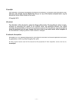
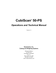
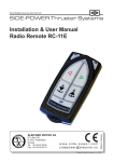
1
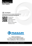
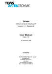
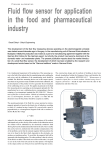
SLEIPNER MOTOR AS P.O. Box 519 N-1612 Fredrikstad Norway Tel: +47 69 30 00 60 Fax: +47 69 30 00 70 w w w. s i d e - p o w e r. c o m s i d e p o w e r @ s l e i p n e r. n o Made in Norway Installation & User Manual Radio Remote 8980 / 8981 © Sleipner Motor AS version 3.3 - 2009 Contents Model range................................................................................................................................ 2 Technical speci¿cations .............................................................................................................. 3 Important precautions ................................................................................................................. 4 Receiver installation ................................................................................................................... 6 “Visual” wiring diagram ................................................................................................................ 6 Programming additional transmitters ........................................................................................... 7 Replacing the batteries ............................................................................................................... 8 User precautions ........................................................................................................................ 9 How to use Sidepower thrusters................................................................................................ 10 Service Partners ...................................................................................................................... 12 Model range The radio remote control can control a single bow thruster or a bow and stern thruster combined. The receiver can receive the signals of up to four transmitters. Remote control kit (8980) consists of: - Receiver: Part# 8918A - Transmitter (incl. battery): Part# 8981 - Holding bracket for transmitter unit: Part# 8926 Additional transmitters can be ordered separatly: Part# 8981 • Part# 8980 The transmitter and the receiver have the same factory preset code so no programmng is necessary. The battery is already inserted in the transmitter. • Additional transmitter(s) Part#8981 When additional transmitters are to be used, the receiver must be programmed again for all transmitters (please see programming section on page 6). We Sleipner Motor AS declare that this device complies with health and safety requirements according to the Directive 89/336/EEC of 23 May 1989 amended by 92/31/EEC and 93/68/EEC. Installation & User Manual, Radio Remote 8980/8981 Page 2 Technical speci¿cations Model Power feed Frequency (MHz) Adress range Operation temp. Technology HxWxD (mm) Weight (g) Transmitter 8981 2 x 3V battery (type: CR2032) 433,92 65.000 -150C / +550C S.M.T. 95x48x25 60 Receiver 8918A From thruster 433,92 65.000 -150C / +550C S.M.T. 90x60x30 135 Important precautions • • • • • • You must always install at least one original Sidepower panel. With the boat on land, only run the thruster for a fraction of a second, as without resistance it will accelerate very fast to a damaging rpm. This manual is intended to support educated / experienced staff and is therefore not suf¿cient in all details for the correct installation. When installed in boats approved or classi¿ed according to international or special national rules, the installer is responsible for following the demands in accordance with these regulations / classi¿cation rules. The instructions in this guide can not be guaranteed to comply with all different regulations / classi¿cation rules. The transmitter and the receiver have the same factory preset code so no programmng is necessary. When additional transmitters are to be used, the receiver must be programmed again for all transmitters (please see programming section on page 7). If a Sidepower automatic main switch is ¿tted, the “OFF” button on your transmitter will shut off the main switch providing no other control panels are “ON”. Installation & User Manual, Radio Remote 8980/8981 Page 3 Receiver installation Prior to installation, it is important that the responsible installer reads this guide to ensure necessary acquaintance with this product. Warning! • Remote receiver power supply negative lead must be connected to the thrusters`s negative lead. Caution! • Install the receiver minimum 1 meter (3ft and 3in) from high power cables and NMEA cables or other sources of electrical interference, i.e. navigation instruments, radio communication devices, electro motors and generators. • Install the receiver outside of shielded areas for radio signals, i.e. Boxes made of steel or other material with shielding properties. • Install the receiver in a dry environment, with cables pointing downwards. (The receiver assembly is not waterproof.) • When additional transmitters are to be used, the receiver must be programmed again for all transmitters (please see programming section on page 7). • The receiver must have a separate power supply ¿tted with a 5 Amp fuse in the positive lead that has either a separate power switch or is shut of by the thrusters system main power switch. The receiver can not be powered by the thrusters`s control looms even if you ¿nd positive and negative lead there. • Mount the receiver using the two screw holes (please see picture on page 6). Optimised installation (Fig. 1 - 3) • The receiver antenna must be placed in a vertical position minimum 1 meter (3ft 3in) above sea level. • The receiver has an extended antenna of 2 meters (6ft 6in). If there is a problem with signal transferring, try to move the extended antenna to a more optimised position. - Above sea level - Away from sources of electrical interference. Note! Faulty installation will render all warranty given by Sleipner Motor AS void. Installation & User Manual, Radio Remote 8980/8981 Page 4 Installation & User Manual, Radio Remote 8980/8981 Page 5 Receiver installation Receiver Part# 8918A 5A BOW To bow thruster To bow thruster control panel Yellow: Sidepower automatic main switch (optional) Black: 12/24V Batt. - Red: 12/24V Batt. + (5A fuse!) Fused power supply from a circuit with ON/OFF switch! To stern thruster To stern thruster control panel Yellow: Sidepower automatic main switch (optional) Sleipner Motor AS • Norway www.side-power.com Mount the receiver by using the 2 screwholes. STERN To bow thruster To bow thruster control panel Yellow: Sidepower automatic main switch (optional) Black: 12/24V Batt. Red: 12/24V Batt. + (5A fuse!) Fused power supply from a circuit with ON/OFF switch! 5A STERN Receiver Part# 8918A BOW Visual wiring diagram To stern thruster To stern thruster control panel Yellow: Sidepower automatic main switch (optional) Sleipner Motor AS • Norway www.side-power.com Installation & User Manual, Radio Remote 8980/8981 Page 6 Programming additional receivers Receiver Part# 8918A 5A BOW To bow thruster Black: 12/24V Batt. - To bow thruster control panel Yellow: Sidepower automatic main switch (optional) Red: 12/24V Batt. + (5A fuse!) Fused power supply from a circuit with ON/OFF switch! To stern thruster To stern thruster control panel Yellow: Sidepower automatic main switch (optional) Sleipner Motor AS • Norway www.side-power.com STERN LED PROG The original transmitter and receiver have the same factory preset code so that no programming is necessary. When additional transmitters are to be used, the receiver must be programmed again for all transmitters. 1. Deactivate the receiver and all transmitters (press “OFF” on all transmitters). Turn off the main power switch for the thruster(s). 2. Turn on the power to the receiver. 3. Remove the plastic plug from the receiver box (as shown above). 4. Press the “PROG” button at the receiver. The receiver is then in “Program mode”. The receiver will stay in Program mode for 30 seconds,indicated by blinking LED 5. The receiver and transmitter are programmed by pressing both “ON” buttons on the transmitter for about 2 seconds. During this 2 seconds the LED will change from blinking to continous light when the programming signal is received. Turn off transmitter. 6. Additional transmitters must be programmed according to step 5 within the same 30 seconds time period when the receiver is in “Program mode”. 7. Wait until the LED stops to blink. The total “Program mode” time is about 30 seconds. The programming is now ¿nished. 8. Turn on the transmitter(s) and check that the receiver LED is blinking slowly (User mode) 9. Turn off the power to the receiver and put the plastic plug back in place. Installation & User Manual, Radio Remote 8980/8981 Page 7 Replacing the batteries Batteries WARNING: Before working on the transmitter, deactivate the transmitter and the receiver (push “OFF” on the transmitter(s)) and turn off the power to the receiver as well as the thruster mainswitch. 1. Open the transmitter. 2. Take out the batteries. 3. Insert the new batteries (Type CR2032, 3V - Brand name recommended). Be sure to insert the battery with the positive pole up. 4. Close the transmitter. Put the cover back in place, ensure that the rubber seal between remote upper and lower part is located correctly. Place the 3 screws (remember sealing washer) in their recessed holes and tighten. Installation & User Manual, Radio Remote 8980/8981 Page 8 Important user precautions • Ensure that you know the location of the main battery switch that disonnects the thruster from all power sources (batteries) so that the thruster can be turned off in case of a malfunction. • If a Sidepower automatic main switch is ¿tted, the “OFF” button on your transmitter will shut off the main switch providing no other control panels are “ON”. • How to activate the system Turn on the main power source for the thruster system. Turn on the power to the receiver. The thruster system is then activated by pushing the two “ON” buttons on the transmitter (see page 9). To turn of the radio remote control push the “OFF” button on the transmitter. • ‘Auto-Off’ after appr. 4 minutes for safety reasons When using a single transmitter The system turns off automatically appr. 4 minutes after the last usage. When using more than one transmitter or additional ‘radio-link’ control panels The system turns off automatically appr. 4 minutes after the last usage of the control unit that initially activated the system even if other control units have been operated in the meantime. The system is off even if these other control units still show the blinking LED on the transmitter. To use these transmitters, the system must be activated again by pushing the two “ON” buttons. • Remember to turn off the radio remote control by pushing the “OFF” button on the transmitter and to turn off the power switch for the receiver when you have ¿nished your maneuvering. • The maximum continues usage time of the electrical thruster is approx. 3 minutes. The electro motor has a built in thermal cut-off switch that will shut it off when overheating and re-engage it when it has cooled down some. This should be considered when planning your manouvering. • Never use a thruster close to somebody in the water, as the thruster will draw objects close by into the tunnel and contact with the rotating propellers will cause serious injuries. • Never run a thruster for more that one second when the boat is not in the water, as this can damage the electromotor seriously. • If the thruster stops giving thrust while the electromotor is running, chances are that there is a problem in the drive-system. You must then immediately stop trying to run it, and turn it off, as running the electromotor for more than a few seconds without resistance from the propeller, can cause serious damage to the electromotor. • When leaving the boat always turn off the main power switch for the thruster and turn off the power to the receiver. • We advice to always keep the main engine(s) running while using a thruster. This will keep the batteries in a good charge condition. This will also give better performance to the thruster, as a higher voltage at the thruster results in a higher torque (power) in the electromotor. • Make sure that only one control is used at the same time, if two panels are operated in opposite directions at the same time the thruster will not run at all. If they are operated in the same direction the thruster will run in this direction. Installation & User Manual, Radio Remote 8980/8981 Page 9 Remote control “ON” Remote control “OFF” 7urn boat to 3ort Bow + Stern thruster Turn boat to Starboard Auto-OFF aSSr min How to use a bowthruster 1. Turn the main power switch for the bow thruster on. Turn on the power to the receiver. 2. Turn on the transmitter by pushing the transmitter’s two “ON” buttons. The remote system is now activated and then turns off automatically appr. 4 min. after the last usage (see page 9). 3. Please take some time to exercise thruster usage in open water to avoid damages to your boat. 4. Turn the bow in the desired direction by pushing the red button for port movement or the green button for starboard movement. How to use a bow & stern thruster combined The combination of a bow and stern thruster offers total manouverability to the boat and the opportunity to move the bow and the stern separately of each other. The remote middle buttons gives you the opportunity to operate both thrusters in the same direction with one keypress, making sidewards movement easier. Remote Control Deactivation Push the transmitter’s “OFF” button (the remote control deactivates automatically after appr. 4 minutes after the last usage). Turn off the power switch for the receiver. ,I in doubt tr\ in oSen water ¿rst ,nstallation & 8ser 0anual Radio Remote 3aJe Electric schematics Receiver 5DGLRPRWWDNHU Insulation LVRODVMRQVWU¡PSH Optional Auto main switch (YWWLODXWRKRYHGEU\WHU +12/24V supply 9)RUV\QLQJ .DQDO$ 6LJQDORXWSXW9 6LJQDORXWSXW9 Optional Auto main switch (YWWLODXWRKRYHGEU\WHU +12/24V supply 9)RUV\QLQJ 6LJQDORXWSXW9 .DQDO% 6LJQDORXWSXW9 Page 11 Installation & User Manual, Radio Remote 8980/8981 Active antenna $NWLYGHODYDQWHQQH PDQWHQQHIRUOHQJHU 2m antenna extension (Yellow) *8/ Red 5' Blue %/c Grey *5c SRORJSRO.RQWDNWKXV +12/24V supply for receiver 9)RUV\QLQJUDGLRPRWWDNHU Channel A Channel B (Yellow) *8/ Red 5' Blue Grey *5c %/c Red 5' Black 6257 4-lead & 1-lead connector