1
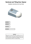
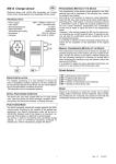
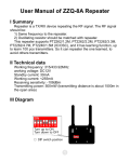
Automation@Home
www.automation-at-home.com
PLCBUS Universal Controller
Version 0.0.28
User Manual
Automation@Home
www.automation-at-home.com
Supported Hardware :
i)
PLCBUS-1141 PLCBUS USB Computer Interface
ii)
PLCBUS-1142 PLCBUS USB RF Computer Interface ( 433.92MHz)
iii)
X10-1140 / 1141
X10 RS-232 RF Computer Interface ( 433.92MHz)
Function Comparison Table :
PLCBUS-1141
PLCBUS-1142
X10-1140 / X10-1141
ON
※
※
※
OFF
※
※
※
DIM
※
※
※
BRIGHT
※
※
※
PRESET DIM
※
ALL LIGHTS ON
※
※
※
ALL LIGHTS OFF
※
ALL UNITS OFF
※
※
※
ALL USER LIGHTS ON
※
ALL USER LIGHTS OFF
※
ALL USER UNITS OFF
※
Basic Command Section
Address Setup Section
Main Address Setup
※
Scenes Address Setup
※
Scenes Address Erase
※
Erase All Scenes Address
※
Troubleshoot Section
Get Signal Level
※
Get Noise Level
※
Status Request
※
Enquiry ON Address
※
Enquiry Occupied Address
※
Automation@Home
www.automation-at-home.com
Installation of Hardware ( PLCBUS-1141 )
1)
Download and Install the USB Serial Controller Driver
http://x10-hk.com/store/download/windows-wd_pl2303h-hx-x_v20019v2021.zip
2)
Plug the PLCBUS-1141 into the available USB port
3)
Right Click “My Computer” and select “Properties” , select third tab “Hardware” and click “Device Manager”
4)
Check the assigned COM port under “COM and LPT” section , see figure 1.1 e.g. COM2
Figure 1.1
Setup PLCBUS Universal Controller Program
1
Run the plcbus1141.exe
2
Select the controller to “PLCBUS-1141” and select the com port , see figure 2.1
3
Click “Open COM Port” for init. the controller.
Figure 2.1
Automation@Home
www.automation-at-home.com
Function : Phase Setting and User Code Section
Phase Setting :
PLCBUS support One Phase and Three Phase power system , you must select the correct Phase Setting
to make the program to control your PLCBUS devices
User Code :
Each PLCBUS system have different User Code , that mean beside House Code and Unit Code ,
PLCBUS device will have User Code to identify their address. PLCBUS address combination is :
(250)User Code + (16)House Code + (16)Unit Code , that mean total 64,000 address.
You must input the correct User Code into the program and make the program to control your PLCBUS
devices. See figure 3.1
User Code in the program is in Hex format , you can check your current user code by press “Check User
Code” button. For more detail , please go to chapter ???
Figure 3.1
Function : Basic Command Section
For all the command under Basic Command Section , you must select the desire House Code and Unit Code.
See figure 3.1
ON Command :
Press ON command button , program will send out ON command with ACK response. E.g. in figure
3.1 , press ON command button , it will send A1 ON command. If the device receive the ON command successfully ,
it will return the ACK and the light of ACK at the upper right corner will turn into Green color for five seconds.
OFF Command :
Press OFF command button , program will send out OFF command with ACK response. E.g. in figure
3.1 , press OFF command button , it will send A1 OFF command. If the device receive the OFF command
successfully , it will return the ACK and the light of ACK at the upper right corner will turn into Green color for five
seconds.
Automation@Home
www.automation-at-home.com
Bright Command :
Press BRIGHT command button , program will send out BRIGHT command with ACK response. E.g.
in figure 3.1 , press BRIGHT command button , it will send A1 BRIGHT command. If the device receive the BRIGHT
command successfully , it will return the ACK and the light of ACK at the upper right corner will turn into Green color
for five seconds.
DIM Command :
Press DIM command button , program will send out DIM command with ACK response. E.g. in figure
3.1 , press DIM command button , it will send A1 DIM command. If the device receive the DIM command
successfully , it will return the ACK and the light of ACK at the upper right corner will turn into Green color for five
seconds.
PRESET DIM Command :
For PRESET DIM command , it have two parameter , one is BRIGHT LEVEL in % , another one is
FADE RATE in number of seconds ( Default is 3 seconds ).
For example , if you select BRIGHT LEVEL is 50% , FADE RATE is 10 Secs , that mean the PLCBUS
dimmer devices will bright to 50% in 10 seconds.
Select your desire BRIGHT LEVEL and FADE RATE and Press PRESET DIM command button ,
program will send out PRESET DIM command with ACK response. E.g. in figure 3.1 , press PRESET DIM command
button , it will send A1 PRESET DIM command to bright to 100% bright in 3 seconds. If the device receive the
PRESET DIM command successfully , it will return the ACK and the light of ACK at the upper right corner will turn
into Green color for five seconds.
ALL LIGHTS ON Command :
By press ALL LIGHTS ON command button , program will send out ALL LIGHTS ON command , and
all the lights under the specific House Code will turn ON . See figure 3.1 , if press ALL LIGHTS ON command button ,
all the lights under House Code A will turn ON.
Factory default , all the PLCBUS dimmer module will response ALL LIGHTS ON command . And all
the PLCBUS appliance module will NOT response ALL LIGHTS ON command. For more detail , please see
Appendix A
ALL LIGHTS OFF Command :
By press ALL LIGHTS OFF command button , program will send out ALL LIGHTS OFF command ,
and all the lights under the specific House Code will turn OFF . See figure 3.1 , if press ALL LIGHTS OFF command
button , all the lights under House Code A will turn OFF.
Factory default , all the PLCBUS dimmer module will response ALL LIGHTS ON command . And all
the PLCBUS appliance module will NOT response ALL LIGHTS OFF command. For more detail , please see
Appendix A
Automation@Home
www.automation-at-home.com
ALL UNITS OFF Command :
By press ALL UNITS OFF command button , program will send out ALL UNITS OFF command , and
all the device under the specific House Code will turn OFF . See figure 3.1 , if press ALL UNITS OFF command
button , all the device under House Code A will turn OFF.
ALL USER LIGHTS ON Command :
By press ALL USER LIGHTS ON command button , program will send out ALL USER LIGHTS ON
command , and all the lights under the specific User Code will turn ON . See figure 3.1 , if press ALL USER LIGHTS
ON command button , all the lights under User Code “D1” will turn ON.
Factory default , all the PLCBUS dimmer module will response ALL USER LIGHTS ON command .
And all the PLCBUS appliance module will NOT response ALL USER LIGHTS ON command. For more detail ,
please see Appendix A
ALL USER LIGHTS OFF Command :
By press ALL USER LIGHTS OFF command button , program will send out ALL USER LIGHTS OFF
command , and all the lights under the specific User Code will turn OFF . See figure 3.1 , if press ALL USER LIGHTS
OFF command button , all the lights under User Code “D1” will turn OFF.
Factory default , all the PLCBUS dimmer module will response ALL USER LIGHTS OFF command .
And all the PLCBUS appliance module will NOT response ALL USER LIGHTS OFF command. For more detail ,
please see Appendix A
ALL USER UNIT OFF Command :
By press ALL USER UNIT OFF command button , program will send out ALL USER UNIT OFF
command , and all the devices under the specific User Code will turn OFF . See figure 3.1 , if press ALL USER UNIT
OFF command button , all the devices under User Code “D1” will turn OFF.
Function : Address Setup Section
MAIN ADDRESS SETUP :
By press MAIN ADDRESS SETUP command button , program will send out the command to change
the specific main address into desire main address. Remind you that , you MUST turn on the specific device first for
response this command.
For example :
You want to Change House A Unit Code 2 into House Code B Unit Code 7
Turn on House Code A and Unit Code 2 first.
In the “Orginal” box at the left , please select which device that you want to change address , e.g.
House Code A , Unit Code 2
In the “New \ Scenes Address” box at the right , please select your desire address , e.g. House
Code B , Unit Code 7
Then press MAIN ADDRESS SETUP command button , at this moment , the device will turn
OFF that mean the command run successfully , after that the device main address will become B7
Automation@Home
www.automation-at-home.com
SCENES ADDRESS SETUP
Each PLCBUS device have One Main Address and 16 Scenes Address.
You can group some different main address devices and assign one scenes address to them for
Scenes Management. E.g. Scenes E1 is Dinner , Scenes E2 is Watch DVD
Example one ( Scenes E1 , Dinner Mode ):
Now , you have four PLCBUS devices as follow :
House Code A , Unit Code 1 , Appliance Module ( Non-Dimmable )
House Code B , Unit Code 2 , Appliance Module ( Non-Dimmable )
House Code C , Unit Code 3 , Dimmer Module ( Dimmable )
House Code D , Unit Code 4 , Dimmer Module ( Dimmable )
Goal : Setup an Scene Address E1 and under this scene :
A1 , B2 will TURN ON
C3 , D4 will Dim to 50% Bright
Step 1 : Turn on A1 and B2
Step 2 : Use PRESET DIM command to set the C3 and D4 into 50% Bright
Step 3 : Under “NEW \ SCENES ADDRESS” box , select House Code E , Unit Code 1 ,
Scenes ON
Step 4 : Press SCENES ADDRESS SETUP command button and the program will send out the
command , and then A1 , B2 , C3 and D4 will turn OFF and turn ON again , that mean
now you already assign E1 scenes address to those devices.
Step 5 : Use any controller to send out E1 ON , A1 and B2 will turn ON , C3 and D4 will dim to
50% Bright
Example Two ( Scenes E2 , Watch DVD Mode ):
Now , you have four PLCBUS devices as follow :
House Code A , Unit Code 1 , Appliance Module ( Non-Dimmable )
House Code B , Unit Code 2 , Appliance Module ( Non-Dimmable )
House Code C , Unit Code 3 , Dimmer Module ( Dimmable )
House Code D , Unit Code 4 , Dimmer Module ( Dimmable )
Goal : Setup an Scene Address E2 and under this scene :
A1 , B2 will TURN OFF ( No matter they are ON or OFF , final result will OFF )
C3 , D4 will Dim to 30% Bright
Step 1 : Turn on A1 and B2
Step 2 : Under “NEW \ SCENES ADDRESS” box , select House Code E , Unit Code 2 ,
Scenes OFF
Step 3 : Press SCENES ADDRESS SETUP command button and the program will send out the
command , and then A1 , B2 will turn OFF and turn ON again
Step 4 : Use PRESET DIM command to set the C3 and D4 into 30% Bright
Automation@Home
www.automation-at-home.com
Step 5 : Under “NEW \ SCENES ADDRESS” box , select House Code E , Unit Code 2 ,
Scenes ON
Step 6 : Press SCENES ADDRESS SETUP command button and the program will send out the
command , and then C3 , C4 will turn OFF and turn ON again
Step 7 : Use any controller to send out E2 ON , A1 and B2 will turn OFF ( No matter they are ON
or OFF , final result will be turn ON) , C3 and D4 will dim to 30% Bright
SCENES ADDRESS ERASE
ERASE ALL SCENES ADDRESS
Function : Troubleshoot Section
GET SIGNAL LEVEL :
Select your desire enquiry signal level’s device House Code and Unit Code under Troubleshoot
section. And then press GET SIGNAL LEVEL command button , it will send out the command and display the Signal
Level at the right hand side.
GET NOISE LEVEL :
Select your desire enquiry noise level’s device House Code and Unit Code under Troubleshoot
section. And then press GET NOISE LEVEL command button , it will send out the command and display the Noise
Level at the right hand side.
STATUS REQUEST :
Select your desire enquiry status’s device House Code and Unit Code under Troubleshoot section.
And then press STATUS REQUEST command button , it will send out the command .
And it will display the current device status :
LED in RED color mean the device is OFF
LED in GREEN color mean the device is ON
Bright Level = x % ( The current bright level for dimmer module )
Fade Rate = x Secs ( The current fade rate for dimmer module )
ENQUIRY ON ADDRESS :
Select your desire enquiry House Code under Troubleshoot section and press ENQUIRY ON
ADDRESS command button , it will send out the command.
And it will display the result at the bottom 16 LED
Example :
You select House Code A and press the ENQUIRY ON ADDRESS command button and then :
Number 2 , 4 and 7 LED in GREEN Color , all the others in RED Color , that mean A2 A4 and A7 is
turn ON , all the others under House Code A is turn OFF
ENQUIRY OCCUPIED ADDRESS :
Select your desire enquiry House Code under Troubleshoot section and press ENQUIRY
Automation@Home
www.automation-at-home.com
OCCUPIED ADDRESS command button , it will send out the command.
And it will display the result at the bottom 16 LED
Example :
You select House Code A and press the ENQUIRY OCCUPIED ADDRESS command button and
then :
Number 1 , 2 and 3 LED in GREEN Color , all the others in RED Color , that mean A1 A2 and A3 is
already occupied by PLCBUS devices , all the other address under House A is available.
This command only can check which address is occupied by PLCBUS Device’s MAIN ADDRESS
only , not support Scenes Address.
Function : RX Frame Section
Under RX Frame box , it will display the PLCBUS signal on the power line and display in HEX format.
CLEAR :
Once you press the CLEAR button , it will clear the on-screen data that show on RX Frame box.
WRITE TO FILE :
Once you press the WRITE TO FILE button , it will save the on-screen data that show on RX Frame
box into text file format and write the file name as plcbus1141.log
CHECK USER CODE :
When you press the CHECK USER CODE button , it will prompt an dialog to show you the Last
Received PLCBUS signal ‘s User Code in HEX format
For example , if you want to know the current User Code of your PLCBUS system , please send any
command by PLCBUS-4034 / 4036 Command Center or PLCBUS-4023 RF Transceiver , and then press CHECK
USER CODE button , then it will prompt out an dialog for the current user code.
Automation@Home
www.automation-at-home.com
Appendix A : PLCBUS devices command support table
Module Type
ALL LIGHTS
ON
ALL LIGHTS
OFF
ALL UNIT
OFF
PLCBUS-2263
One Load Dimmer
※
※
※
PLCBUS-2264
Two Load Dimmer
※
※
※
PLCBUS-2267
One Load Appliance
△
△
※
PLCBUS-2268
Two Load Appliance
△
△
※
PLCBUS-2026 UK/G/AU
One Load Dimmer
※
※
※
PLCBUS-2027 UK/G/AU
One Load Appliance
△
△
※
PLCBUS-4023 UK/G/AU
One Load Appliance
△
△
※
PLCBUS-2220
One Load Dimmer
※
※
※
PLCBUS-2221
Two Load Dimmer
※
※
※
PLCBUS-2224
One Load Appliance
△
△
※
PLCBUS-2225
Two Load Appliance
△
△
※
PLCBUS Micro Module
PLCBUS Plug-in Module
PLCBUS Wall Switch
△
= Factory default is NOT support this command but it is programmable
※
= Factory default is support this command