1
PELTIER TEMPERATURE CONTROLLER
A Design Project Report
Presented to the School of Electrical and Computer Engineering of Cornell University
In Partial Fulfillment of the Requirements for the Degree of
Master of Engineering, Electrical and Computer Engineering
Submitted By
Hanting Lu
MEng Field Advisor: Bruce Land
MEng Outside Field Advisor: Bruce Johnson
Abstract
Master of Engineering Program
School of Electrical and Computer Engineering
Cornell University
Design Project Report
Project Title:
Peltier Temperature Controller
Author: Hanting Lu
Abstract: This project is designed to build a controller to control the bath temperature of a
petri dish. The device will be used by student lab of neurobiology to conducting experiments on
fruit flies’ thermo channels. An ideal device should have the following feature: easy to use, small
development budget (less than $100) and satisfying the performance requirement for conducting
experiments. The project is based on an atmega-1284 microcontroller as the main control unit
with a PID control algorithm running inside. The petri dish’s bath temperature is heated or
cooled by a Peltier Plate. A Thermistor is used as the temperature detection device and sent
feedback to the microcontroller regarding to current bath temperature of the petri dish. All
components are connected with analog circuits to form a close loop feedback controller in order
to dynamically control the petri dish’s bath temperature. Graphic user interface is built with
MATLAB to provide easy user access and monitoring.
Executive Summary
This Master of Electrical and Computer Engineering project is designed to control the bath
temperature of a petri dish through a microcontroller-based system. It provides a way for
students in neurobiology lab to conduct experiments on a temperature sensitive channel of fruit
flies. This system should have an easy-to-use graphical user interface (GUI) so that students can
use it easily with a simple user manual. It is also required to have a development budget under
$100.
The design and implementation of the project has completed and the first version of the
device is ready to use. The device has an average rising time of 5s/℃ and settles within 10s.
Tests shows it works stable and accurate among the range of 15 ~ 35 ℃ which satisfies the
requirement. The total cost is less than 100$ and with a simple user manual students can easily
use it to conduct related lab experiments.
The final product contains two parts: a control unit and an execution unit. The control unit
packages all the circuits as well as the microcontroller into a project box. The execution unit is a
peltier-thermistor based platform where the petri dish should be put. The complexity and detail
of both units are hidden from the user. Separating the two units also largely reduce the negative
influence the control circuits may have on electronic noise. To use the device, user only need to
follow the user manual to connect two units together and plug in the power supply. In order to
make the device more user friendly, a GUI is implemented using MATLAB. The interface is very
easy to understand and use. User only needs to type the desired temperature into the GUI
interface. The value will then be passed to the microcontroller by serial communication. The
interface also contains a dynamic plot to allow the user to monitor the trend of the temperature.
Table of Contents
1. Introduction .................................................................................................................................... 1
1.1 Background and Motivation .................................................................................................................. 1
1.2 Problem Statement & Constrains ......................................................................................................... 1
1.3 Range of Solutions .................................................................................................................................... 1
1.4 Project Design Overview ......................................................................................................................... 2
1.5 Design Specification.................................................................................................................................. 2
2. System Design ................................................................................................................................. 3
2.1 High-level Design ...................................................................................................................................... 3
2.2 Control Unit Design ..................................................................................................................................... 3
2.2.1 PID Controller ...................................................................................................................................................... 3
2.2.2 Peltier Plate .......................................................................................................................................................... 4
2.2.3 Control Circuits ................................................................................................................................................... 5
2.3 Temperature Detection Unit .............................................................................................................. 7
2.4 Graphical User Interface ........................................................................................................................ 8
2.5 Microcontroller Pin Assignment ............................................................................................................ 9
2.6 Combine Together ................................................................................................................................. 10
3. Implementation and Packaging ............................................................................................. 11
3.1 Project Box .............................................................................................................................................. 11
3.2 Peltier-thermistor Platform ............................................................................................................ 12
3.3 Stand-alone Program ......................................................................................................................... 12
4. Tests and Results ......................................................................................................................... 13
4.1
4.2
Maximum Output Voltage Test .......................................................................................................... 13
Tuning PID arameters .......................................................................................................................... 13
5. Conclusion...................................................................................................................................... 14
6. Acknowledgement ...................................................................................................................... 14
7. Reference ....................................................................................................................................... 15
Appendix A User Manual .................................................................................................................. 16
Appendix B Cost ................................................................................................................................... 20
Appendix C Microcontroller Source Code ................................................................................... 21
Appendix D MATLAB Script ............................................................................................................. 25
MEng Project Report
1.
Hanting Lu
Introduction
1.1 Background and Motivation
Fruit flies (Drosophila) can be engineered to have thermo sensitive channels, which are
useful for turning off and on function in biological experiments. One of these channels to be
considered as a promising new tool is called Drosophila Transient Receptor Potential channel
(dTRPA1). This is a temperature and voltage-gated cation channel that regulates drosophila
behavior related to different temperature environment. Previous work has shown that neurons
expressing dTRPA1 begin firing action potentials when ambient temperatures rise above 25°C.
By delivering modest heat pulses, sets of neurons can be remotely activated in freely behaving
animals.[4]
To observe and analyze the neurons’ response to the heat stimulus, students who conduct this
experiment need a device which can give heat pulse to drosophila. A simple way to achieve
this goal is to give a random voltage to a peltier plate so that heat is generated to increase the
bath temperature of the petri dish. However, this “open-loop” method has an obvious problem
that the heat pulse cannot be controlled. In other words, people can only give a positive or
negative voltage to the peltier plate to either increase or decrease its surface temperature,
however, the detailed amount of degrees the bath temperature will be changed is not controllable.
To conduct experiments more accurately and controllable, a feedback temperature controller is
needed.
1.2 Problem Statement & Constrains
There are devices on the market which satisfied the lab requirement mentioned in the last
section. However, these devices have two problems. First, the price of the existing device is
expensive. Most of them cost more than one thousand dollars. Second, the way to use the device
is complicated because the device may have other functions that are fancy but redundant. As a
result, a ideal device should be inexpensive and easy to use. With the help of a simple user
manual, students conducting the experiment don’t have to bother too much on learning how to
use the device.
Despite constrains on cost and complexity, the low-noise environment is required in the lab
so that PWM is unacceptable. Furthermore, in order to eliminate the electronic noise, the control
circuits (power supply, DAC, power amplifier, etc.) have to be completely separated and keep
distance from the petri dish. Based on these constrains, the section 1.5 lists the design
specification for this project required by students lab of neurobiology.
1.3 Range of Solutions
Previous work has been done to attempt to build a temperature controller. An in expensive
way is proposed by Correges P, Bugnard E, Millerin C, Masiero A, Andrivet JP, Bloc A, Dunant
Y[1] mentioned the usage of peltier plate but since no control cirtuit was used, the precision was
low. But the idea of using peltier plate as an inexpensive way of generating heat is adopt in this
project design. Other works tried with electronic device or circuits but either had a relatively
higher cost or may lack an easy way to use the device (GUI, LCD monitor, etc.). [2][3][5][6]
1
MEng Project Report
Hanting Lu
The range of solutions can be divided into two categories, pure analog circuit design and
microcontroller-based design.
It is possible to build a pure analog circuit function as a temperature control unit. The
advantage of this design is a quick speed execution. However, since a GUI interface is required,
this solution is not the best for this project design problem. On the other hand,
microcontroller-based design provides a serial communication that can be used to build a GUI
interface on any computer. With a proper algorithm implemented, the response speed of the
microcontroller is fast enough to satisfy the specification. The next section gives an overview of
the scheme to design this project. Design detail of each Unit is discussed in section 2.
1.4 Project Design Overview
The system can be divided into three parts, which are temperature detection unit, temperature
control unit and GUI user interface. In order to detect the current bath temperature, a thermistor
along with a voltage divider circuit is used. When sensing the different temperature, thermistor
will have different resistance which is reflected as a different voltage drop in the voltage divider
circuit. By continuously taking ADC samples from this voltage, the microcontroller can get the
information about the current bath temperature of the petri dish.
For the temperature control unit, the main components include an atmega-1284
microcontroller with a PID control implemented, difference amplifier circuit, digital to analog
(DAC) circuit and a power amplifier circuit. The microcontroller outputs control signals based
on the desired temperature it get from user and the current temperature detected by the thermistor.
The DAC and difference amplifier is used to convert the eight bits output from microcontroller to
an analog signal ranging from -12V to +12V. The control signal is then output through a power
amplifier to drive the peltier device to either increase or decrease the bath temperature of the
petri dish.
For the GUI interface, MATLAB is chosen as a foundation. The interface is designed to be
easy to understand and use. To use the device, user only need to type the desired temperature into
the GUI interface. The value will then be passed to the microcontroller by serial communication
using USB. The interface also contains a dynamic plot to allow the user to monitor the trend of
the current bath temperature in petri dish.
1.5 Design Specification
The following is the design specification, note that it’s not the final result of the product but a
minimum requirement to ensure the product can be used for related experiments.
Cost: less than 100$
Rising time: 12s /℃ (settled within 10 s)
Temperature range: 20 ~ 30 ℃
Design requirement: low noise, low cost, easy to use
2
MEng Project Report
Hanting Lu
2. System Design
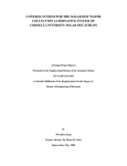
2.1 High-level Design
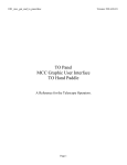
Figure 1 illustrates the overview of the project design. As the diagram shows, the device can
be divided into three parts: temperature control unit, temperature detection unit, and GUI
interface. The temperature detection unit keeps detecting the current bath temperature of the petri
dish and sending it back to microcontroller. The control unit starts from running the PID control
algorithm inside the microcontroller based on the current temperature detected by thermistor and
the desired temperature input by the user through the GUI interface. The output from the
microcontroller went through the digital to analog converter, a difference amplifier and then a
power amplifier. The signal after the power amplifier will have enough power to drive the peltier
plate to distribute or absorb heat on its surface.
Figure 1. Overview of the Project
2.2 Control Unit Design
2.2.1 PID Controller
The control unit starts when the microcontroller receives the desired temperature from user.
There is a PID control algorithm implemented inside the microcontroller which output the
3
MEng Project Report
Hanting Lu
control signal based on the current temperature detected from thermistor and the desired
temperature. Considered as one of the best and common use controller in industrial control
systems, PID controller can provide control action design for specific process requirement by
tuning the three parameters. The three parameters are the proportional (P), the integral (I), and
derivative (p) values. P depends on current error, I on the accumulation of past errors, and D
keep track on the trends of future errors. The weighted sum of these three values provides the
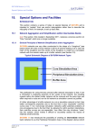
control signal to the peltier plate. Figure 2 illustrate the flow chart of a typical PID controller.
The value of P, I, D was calibrated by the required specification of the device (listed in
section 1.5). The rising time should be less than 12 second per 1 Celsius degrees rising from 20
to 30℃. The temperature should be settled within 10 seconds after reaching the desired
temperature. Under this requirement, the way to get the P, I, and D is to start from calibrating the
proportional gain and left other two zero. After a proper P is set so that the rising time is satisfied
for the requirement, D is than modified to smooth the overshooting. By setting a proper P and D,
the controller is smooth enough but with a steady state error around 3 Celsius degree. Then
Integral gain is modified to eliminate the steady state error.
Figure 2. PID Controller Flow Chart
2.2.2 Peltier Plate
This section briefly introduces the principle of a typical modern peltier plate. A peltier plate
is based on the thermoelectric effect. A typical thermoelectric device works one of two ways as
follow: It creates voltage when there is a different temperature on each side of the device, or
conversely, it creates a temperature difference on each side of the device when a voltage is
4
MEng Project Report
Hanting Lu
applied to it. Peltier plate is known for the second way described above. Specifically, in figure 3,
when the voltage difference is positive between wire a and b, surface A will generate heat while
surface B will absorb heat. However, when a negative voltage appears between wire a and b,
then the opposite effect occurs. With its quick response, and an inexpensive price on market,
peltier plate serves as a good component for this temperature controller design.
Figure 3. Peltier Plate Working Demo
2.2.3 Control Circuits
Because of the output current limitation of the microcontroller, the control signal coming out
from microcontroller has to be amplified and shifted to drive the peltier plate. The ideal result is
that the driving voltage of the peltier plate has a range -12V ~ +12V. In order to reach this goal, a
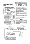
circuit schematic shows in figure 4 is designed. This circuit is composed with three main parts: A
digital to analog converter (DAC), A difference amplifier and a power amplifier.
5
MEng Project Report
Hanting Lu
Figure 4. Control Circuit
The DAC is a 4114R-2-RC which can convert an eight-bit digital input to an analog output. A
5 volts from output pin is a logic “1” and a 0 volts corresponds to a logic “0”. The combination
of the eight output pins from microcontroller forms a range from 0 to 3.2 V at DAC’s output.
Because the peltier plate requires a switching of the voltage’s direction to either absorb or
distribute the heat, the control signal has to be shifted to generate a “negative” voltage. Moreover,
the voltage has to be amplified to achieve the full swing of the peltier plate. (-12V~+12V) To
achieve this result, a difference amplifier is added into the circuit. The buffer before the negative
input is to separate the voltage divider from the rest circuits so that the voltage of the negative
input can be decided only by the voltage divider. After the difference amplifier, the output range
is shifted and amplified to -12V ~ +12V.
Since the peltier plate has a power consumption of 60W, which means a 5A current under
12 volts drive, a power amplifier is needed to drive the peltier plate. The circuit is built as shown
in figure 4. In ideal situation, the output of the power amplifier should has a range of -12V ~12V.
However, because of the voltage drop caused by the CMOS transistor, the actual output has a
range of -6V ~ 6 V. Unfortunately, the performance is downgraded by half compared to the
original design. However, in section 4 the test result will prove that this output range is large
enough (Actually the final output is -4.5V ~+6V limited by the over heating problem of PMOS).
By tuning the PID parameters, the output control signal satisfied the system requirement. More
detail result is showed in section 4.
6
MEng Project Report
Hanting Lu
2.3 Temperature Detection Unit
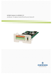
The Temperature Detection Circuit is illustrated in figure 5. It is a voltage divider with a
thermistor inserted as a variable resistor. As the thermistor I used is a NTC thermistor, its
resistance would decrease as the increasing of the temperature. The disadvantage of using a
thermistor is that its resistance changing is non-linear, which makes it hard to convert back to its
corresponding temperature after ADC sampled by microcontroller. Because the range of the
temperature is not large, I first tried to use a look up table inside the microcontroller. This
scheme worked but the problem is that the look up table is based on the datasheet of the
thermistor, which is unfortunately not very accurate. Furthermore, the error is not regular which
means it is hard to compensate it in software. To get a better look up table I have to measure
every 0.1 degree changing for the thermistor which is not doable. The final solution I took is to
sample enough data for the temperate and its corresponding thermistor’s resistance, and using
MATLAB to find a best-fit function. The function I chose is demonstrated in figure 6. By doing
so, the error is within 0.5℃, which is acceptable for this project.
Figure 5. Temperature Detection Unit
7
MEng Project Report
Hanting Lu
Figure 6. Using MATLAB to Find A Best-fit Function for the Thermistor
2.4 Graphical User Interface
The user interface designed for this project is MATLAB based. The interface is illustrated in
figure 7. Since one of the important requirement for UI is easy-to-use. I try to simplify the
functional buttons’ arrangement on it and make it as simple as possible. The only thing maybe
confused is the text window at the bottom-right corner. The use of that is to set the
communication port for a serial communication between MATLAB and microcontroller. The
communication rate is 9600 baud. The MATLAB function fprint and fscanf does a good job on
communicating with microcontroller. By pressing the “detect” button, the ADC sample from the
temperature detection unit is passed from microcontroller to MATLAB, which then converted to
current bath temperature and is shown in the middle text window. After input the desired
temperature in the bottom left text box and pressing the “start” button, the desired bath
temperature is passed back to microcontroller. The control unit starts to control the bath
temperature. The temperature changing will continually show in current temperature text
window as well as in the dynamic plot. By pressing the “stop” button, the device stop to function
and ready for new command. The detail MATLAB code can be found in Appendix D.
8
MEng Project Report
Hanting Lu
Figure 7. User Interface
2.5 Microcontroller Pin Assignment
The atmel mega 1284 used in this project is developed and used on the development
board used for Cornell ECE4760 course. The detail of this hardware can be found in the
course webpage: http://people.ece.cornell.edu/land/courses/ece4760/ . To illustrate the
pin assignment on the development board, figure 8 is demoed as a simplified version of the
development board. It includes all the pins on the board but the location maybe different.
PC0~7 is used for output the control signal. Thus they are connected to the DAC. PA0 is
the default port for ADC sampling, it is connected to the thermistor. VCC and Gnd are also
connected to the temperature detection unit to finish the voltage divider. An LED is
connected to PD0 to indicate the system is on.
9
MEng Project Report
Hanting Lu
Figure 8. Microcontroller Development Board
2.6 Combine Together
The following process shows the common steps after the system’s power is on. Note it also
reflects the basic coding process on microcontroller since the whole process is controlled by it. A
detailed source code of microcontroller can be found in Appendix C.
Step 1: Power on, LED turned on indicating the system is running. An initial static control signal
is output from microcontroller result in a 0V control voltage on peltier plate.
Step 2: Current temperature is detected by the temperature detection unit and passed to
microcontroller.
Step 3: A desired temperature is input, and passed to the microcontroller.
Step 4: PID algorithm is running based on the error between current temperature and desired
temperature. A dynamic control signal is output to drive the peltier plate. This step is continually
repeated until a “stop” signal is sent from user.
Step 5: Get the “stop” signal, stop the current process and go back to step 1.
10
MEng Project Report
Hanting Lu
3. Implementation and Packaging
3.1 Project Box
In order to separate the control circuits away from the petri dish, all the control circuits are
put separately in a project box including the microcontroller. Since the CMOS generate large
amount of heat when the system is running, heat sink is required for both NMOS and PMOS.
The initial implementation used the small heat sink which can be attached to the CMOS so that
they don’t need to be taken off from the circuit board. However, tests show that these small heat
sinks cannot efficiently distribute the heat away. As a result, big heat sink has to be used and
CMOS has to be moved off the circuit which increase the size of the device. One optimization to
decrease the device size is to build the circuit board in three dimensions. Instead of building all
circuits on one board, circuits are divided into three portions and put on three boards. These
circuit boards are then connected together vertically. This “three-folded sandwich” scheme
effectively saves 1/3 of circuits’ size horizontally and thus decreases the size requirement for the
project box. Same scheme is also used to put one power supply above another.
There are four different types of the connecters on the project box. A USB port is used to
connect to PC for serial communication between microcontroller and GUI. Two banana sockets
are used connect to the peltier plate so that the control signal can be passed from control unit to
the peltier plate. Another two banana sockets are used to connect thermistor of the temperature
detection unit described in section 2.3. Finally a power plug is used to connect to the power
supply. The inside structure of the project is shown in figure 9. Note that there is space saved for
further improvement such as adding a fan to distribute the heat. The size of project box is
14.17×7.87×5.91 inches. Pictures of the project box can be found in Appendix A.
Figure 9. Project Box Structure
11
MEng Project Report
Hanting Lu
3.2 Peltier-thermistor Platform
Since Peltier generates temperature difference on its two surfaces, while one surface is used
to control the temperature of the petri dish, the other has to be attached to a large heat sink to
distribute the heat. Two banana plugs are attached to the input wire of the peltier plate so that it
can be connected to project box. The thermistor is put on the one side above the peltier plate. The
material I used to support the thermistor can be bend over so that the position the thermistor
probes to the petri dish can be adjusted by hand. Another two banana plugs are attached to the
thermistor to connect to the project box. The picture of this peltier-thermistor platform can be
found in Appendix A
3.3 Stand-alone Program
Since the computer in student lab of neurobiology doesn’t have MATLAB installed, a
conversion is needed to make MATLAB script a stand-alone program. Otherwise, purchasing
MATLAB will increase the total development budget. MATLAB’s deploy tool and its MCC
compiler is a good way to convert script to either .exe for windows or .app for MAC. It converts
the script as well as packages it with its GUI library so that a GUI interface can be running on a
computer without installing MATLAB. I tested the windows OS. The whole package appears as
a .exe file and when it is running it automatically installs the compiler and related libraries before
calls the GUI. This solution has been tested well on computers which have no MATLAB
installed. The detail method can be found on MATLAB’s official webpage under deploy tool.
12
MEng Project Report
Hanting Lu
4. Tests and Results
4.1 Maximum Output Voltage Test
In section 2 it states that the actual output voltage after power amplifier is -6V ~ +6V. Since
both CMOS and peltier plate may generate heat during the device running, this maximum
voltage has to be tested to guarantee the device can stand the maximum voltage for a long period
of time. The time period is set to 10 minutes. The results shows that there are no problem for
NMOS and the pletier plate, but the PMOS is overheated and has potential risk to burn out. As a
result, several smaller voltage are tested and it turns out -4.5V is the maximum voltage PMOS
can stand. Modification is then made on microcontroller to set threshold on lowest output voltage
so that the maximum negative output control voltage is -4.5V.
4.2 Tuning PID Parameters
Using the method described in section 2, PID controller is tuned under constrains discussed
in section 4.1. The final value of PID used for the project is listed as follow:
P = 10
I = 50
D = 500
Under this set of parameters the final product’ performance is listed below:
Cost: 94.01$
Rising time: 5s /℃ (settled within 10 s)
Falling time: 10s/℃
Temperature range:
15 ~ 35 ℃
A comparison between the data above and the original design specification shows that the
performance requirements are satisfied. The development cost can be found in Appendix B.
13
MEng Project Report
Hanting Lu
5. Conclusion
The first version of the “Peltier Temperature Controller” has been built and packaged
completely. The device has been tested with different computers and worked well. All the device
specification satisfied the design goal and with a User Manual in Appendix A, students can easily
learn how to use it to conduct related experiments.
For possible future improvement, a better PMOS may be considered to use to increase the
maximum positive voltage. A fan can be added to distribute the heat inside the project box more
effectively. The Cable connected between project box and the peltier plate can be upgraded both
in length and robustness. An LCD screen can be added on the project box so user can use the
device without a computer.
6. Acknowledgement
I would like to thank Professor Bruce Land who served as my MEng field advisor. His
insight full guidance and suggestions always helped me to move forward every time I got stuck
by technical difficulty. His course ECE4760 and ECE5760 also enlighten my understanding on
digital system design which has positive effect on this project. I appreciate his dedication and
commitment to this project.
I would also like to thank Professor Bruce Johnson who served as my MEng outside advisor.
Our meetings were critical for me to calibrate the performance and the future design goal of the
project. He also introduces biology knowledge that is outside my major to me, which I found
very interesting.
14
MEng Project Report
Hanting Lu
7. Reference
Paper:
[1]Correges P, Bugnard E, Millerin C, Masiero A, Andrivet JP, Bloc A, Dunant Y (1998) A
simple, low-cost and fast Peltier thermoregulation set-up for electrophysiology. J Neurosci
Methods 83:177-184.
[2]Forsythe ID, Coates RT (1988) A chamber for electrophysiological recording from
cultured neurones allowing perfusion and temperature control. J Neurosci Methods
25:19-27.
[3]Kingsley RE, Barnes CD, Pompeiano O (1976) A proportional controlled thermoregulator
circuit of simple design. Electroencephalogr Clin Neurophysiol 40:306-308.
[4]Jimena Bemi, Alistair M.Muldal, Stefan R. Pulver, Using Neurogenetics and the
Warmth-Gated Ion Channel TRPA1 to Study the Neural Basis of Behavior in Drosophila, J
Undergrad Neurosci Educ. 2010 Spring; 9(1): A5-A14
[5]Rose G (1983) A temperature controller for in vitro recording chambers. Brain Res Bull
10:713-714.
[6]Tools for Physiology Labs: An Inexpensive Means of Temperature Control, Jacob L.Krans
and Ronald R.Hoy, the Journal of Undergraduate Neuroscience Education, fall 2005, 4(1)
A22-A26
Datasheet:
[7]Atmel mega1248 Microcontroller
[8]IRF 9522 P-Channel Enhancement-Mode Vertical DMOS Power FETs
[9]IRF 520 Power MOSFET
[10]LM 358 Low Power Dual Operational Amplifiers
[11]R/2R Series Thick Film Networks
[12]44105 Thermistor with FEP Sheath
15
MEng Project Report
Hanting Lu
Appendix A User Manual
1. Components
Project Box
Peltier-thermistor Platform
Cable
USB cable
16
MEng Project Report
Hanting Lu
2. Connection
1> Connect one end of the yellow-head cable to the green banana sockets on the
Peltier-thermistor platform. Connect the other end of the cable to the green banana sockets
on the project box. The orders of which plug match which socket doesn’t matter.
2> Connect one end of the red-white-head cable to the red-white banana sockets on the
Peltier-thermistor platform. Connect the other end of the cable to the red-white banana
sockets on the project box. Note that red plug should match the red socket and the white
plug should match the white socket.
3> Connect the USB port on the project box to a computer by the USB cable.
4> Plug in the power. If the red light on the project is on, the system is ready to work.
IMPORTANT: DO NOT OPEN THE PROJECT BOX ANYTIME WHEN POWER IS ON!!!
3. Install Software
Double click the test_pkg.exe file. It will automatically extract the MCC compiler and the
libraries inside this file as the following picture shows:
MCC compiler has to be installed before using the MATLAB GUI interface. After the extraction,
the program will start to install MCC compiler. An installer window will show as the follow:
17
MEng Project Report
Hanting Lu
Click Next and follow the instruction in the installer window to finish installing process.
After completion the install, in addition to the test_pkg.exe file, following files will be shown in
your document: MCRInstaller.exe (the compiler installer), readme.txt, and test.exe.
Double click the test.exe, the GUI interface should be shown on your computer. (You may have
to wait for a while when the program is responding)
4. Running the System
1>
Click
Control
Panel...System...Hardware
Tab...Device
Manager
to find out which serial port is connected to the USB dongle. For
example, the following figure indicating the use of a COM7 port.
Button...+Ports
18
MEng Project Report
2>
3>
4>
5>
6>
Hanting Lu
Input the port ID found in step 1> into the bottom right corner in GUI. Press “set” button.
Press “detect” button, the current bath temperature of petri dish will be shown in the middle
bottom text box.
Input the desired temperature in the left bottom corner text box. Press “start” button. The
device will start running and you should see the current temperature change both in the
middle bottom text box and the dynamic plot.
Press “stop” button to stop the current process. And then another desired temperature can
be input and repeat step 4>.
Press “quit” button when you finish the experiments.
19
MEng Project Report
Hanting Lu
Appendix B Cost
Iterm
Atmaga 1248
Project Box
Peltier+Heat Sink Module
12 V Power Supply
IRF 9522
IRF 520
LM 358
4116 R2R
Unit Cost
$5.00
$29.95
$10.00
$21.98
$1.20
$0.30
$0.40
$0.40
Quantity
1
1
1
2
1
1
3
1
Total
Subtotal Cost
$5.00
$29.95
$10.00
$43.96
$1.20
$0.30
$1.20
$0.40
$92.01
20
MEng Project Report
Hanting Lu
Appendix C Microcontroller Source Code
#define F_CPU 16000000UL
#include <inttypes.h>
#include <avr/io.h>
#include <avr/interrupt.h>
#include <stdio.h>
#include <avr/eeprom.h>
// serial communication library
#include "uart.h"
FILE uart_str = FDEV_SETUP_STREAM(uart_putchar, uart_getchar, _FDEV_SETUP_RW);
#define begin {
#define end }
#define nopress 1
#define maybe
2
#define pressed 3
#define maybeno 4
unsigned char inchar;
volatile unsigned char sw0,sw1;
char des_temp;
volatile unsigned char blinktime;
volatile unsigned char sw, sw0, sw1;
volatile unsigned char swState;
volatile unsigned char swtime;
char temp;
char temp2;
ISR (TIMER0_COMPA_vect)
begin
//switch detection state machine
swtime++;
if (swtime==30)
begin
swtime=0;
switch (swState)
begin
case nopress:
if (PINB!=0xff)
begin
swState=maybe;
sw = PINB;
end
break;
21
MEng Project Report
Hanting Lu
case maybe:
if (PINB==sw)
begin
swState=pressed;
sw = PINB;
sw0 = sw0 + (char)((~sw & 0x80)>0);
sw1 = sw1 + (char)((~sw & 0x40)>0);
end
else swState=nopress;
break;
case pressed:
if (PINB==sw) swState=pressed;
else swState=maybeno;
//sw = PINC;
break;
case maybeno:
if (PINB==sw) swState=pressed;
else swState=nopress;
//sw = PINC;
break;
end //case
end //button state machine
//blink the LED to show it is running
blinktime++;
if (blinktime==200)
begin
PORTD ^= 0x04 ;
blinktime=0;
end //blink routine
end // timer 0 ISR
void main(void)
begin
//UCSR0B = 0b00011000 ; //hex 0x18
//
UBRR0L = 103 ; //using a 16 MHz crystal (9600 baud)
//init the UART -- uart_init() is in uart.c
uart_init();
stdout = stdin = stderr = &uart_str;
fprintf(stdout,"Starting...\n\r");
//crank up the ISRs
//set up timer 0
OCR0A=249;
//1 mSec
TIMSK0= (1<<OCIE0A); //turn on timer 0 cmp match ISR
//set prescalar to divide by 64
22
MEng Project Report
Hanting Lu
TCCR0B= 3;
// turn on clear-on-match
TCCR0A= (1<<WGM01) ;
// blink port
DDRD = 0x04; // and d.2 which runs another LED
DDRA = 0xff;//test led ports
PORTA = 0x00;
// switch port
DDRB = 0x00;
PORTB = 0xc0; // turn on pullups on d.6 and d.7 for pushbuttons
//set state machine
swState = nopress;
sw0=0;
sw1=0;
sei();
while(1)
begin
temp = UCSR0A&0x80;
if (temp)
begin
inchar = UDR0;
//fprintf(stdout,"%d \n\r", inchar) ;
if (inchar=='s')
begin
//fprintf("%d %d\r\n", sw0, sw1);
fprintf(stdout,"%d %d \r", sw0,sw1) ;
//fprintf(stdout,"%d \n\r", sw) ;
sw0=0;
sw1=0;
end else if(inchar >=48 && inchar < 100)//second higher bits is check bit
begin
//fprintf(stdout,"%c \r", 'k');
des_temp = inchar-48;
PORTA = des_temp;
end else if(inchar>=100&&inchar<110)
begin
//fprintf(stdout,"%c \r", 'k');
//des_temp = inchar-128;
des_temp = 7;
PORTA = des_temp;
end
end
end //while(1)
end //main
23
MEng Project Report
Hanting Lu
24
MEng Project Report
Hanting Lu
Appendix D MATLAB Script
%UI interface for temperature controller
clf
clear all
try
fclose(instrfind) %close any bogus serial connections
end
%set(gcf,'CloseRequestFcn','delete')
%define the plot button
start_button=uicontrol('style','pushbutton',...
'string','Start', ...
'fontsize',12, ...
'position',[100,400,60,20], ...
'callback', 'start=1;');
%define the detection button
detect_button=uicontrol('style','pushbutton',...
'string','detect', ...
'fontsize',12, ...
'position',[200,400,50,20], ...
'callback','detect=1;');
%define non-editable text field for showing current temperature
current_temperature=uicontrol('style','text',...
'string','', ...
'fontsize',12, ...
'position',[220,1,100,40]...
);
%define edibale text file for inputing desired temperature
desired_temperature=uicontrol('style','edit',...
'string','0', ...
'fontsize',12, ...
'position',[100,1,100,40] ...
);
%define edibal text field for setting communication port
communication_ports_set=uicontrol('style','edit',...
'string','COM1', ...
'fontsize',12, ...
'position',[400,1,100,40] ...
);
%define the set button
25
MEng Project Report
Hanting Lu
setbutton=uicontrol('style','pushbutton',...
'string','Set', ...
'fontsize',12, ...
'position',[500,1,50,20], ...
'callback','set_C=1;');
%define the quit button
quitbutton=uicontrol('style','pushbutton',...
'string','Quit', ...
'fontsize',12, ...
'position',[500,400,50,20], ...
'callback','quit=1;close;');
%define the stop button
stop_button=uicontrol('style','pushbutton',...
'string','stop', ...
'fontsize',12, ...
'position',[300,400,50,20], ...
'callback','stop=1;');
%make some axes
axeshandle = axes(...
'position',[.2 .2 .7 .7],...
'xlim',[0 100],...
'ylim',[-20 60]);
%initiate button signals
quit=0; %wait for a quit button push
set_C=0;
start=0;
plus = 1;
neg = 0;
detect =0;
stop =0; %wait for a stop command
setbkgnd=0;
saveit=0;
num_s = 0;
flag = 1;
%null out x and y
x=[];y=[];
bkgndcolor = [1,1,1];
time = 0;
frame_begin = 0 ;
frame_end = 100;
26
MEng Project Report
Hanting Lu
frame_limit = 99;
while (quit==0)
pause(1)
%//////drawnow; %need this in the loop for controls to work
if ((set_C == 1) && (flag == 1))
flag = 0
%=====open a serial connection===============================
%set its rate to 9600 baud
%SR830 terminator character is (ACSII 13)
%use fprintf(s,['m' mode]) to write
%and fscanf(s) to read the SR830
port = get(communication_ports_set,'string');
s = serial(port,...
'baudrate',9600,...
'terminator',13);
fopen(s)
end
if (flag == 0)
if start==1
start=0;
Switch = 0;
des_temp = 48+str2num(get(desired_temperature,'string'));
fprintf(s,des_temp)
end
if detect==1
fprintf(s,'s')
Switch = fscanf(s,'%d%d')
num_s = Switch(1) + Switch(2)/10;
plot(time,num_s,'--rs','LineWidth',2,...
'MarkerEdgeColor','g',...
'MarkerFaceColor','g',...
'MarkerSize',2),grid on;
hold on;
if(time>frame_limit)
frame_begin = frame_begin + 100
frame_end = frame_end + 100
frame_limit = frame_limit + 100
;
end
axis([ frame_begin frame_end -20 60]);
time = time +1;
;
;
27
MEng Project Report
Hanting Lu
set(current_temperature,'string',num2str(num_s));
end
if stop==1
stop = 0;
detect = 0;
set(desired_temperature,'string','0');
set(current_temperature,'string','0');
fprintf(s,'t')
end
end
end
if(flag == 0)
fclose(s)
end
28