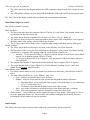
1
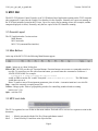
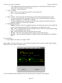
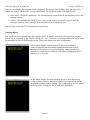
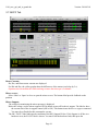
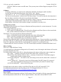
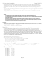
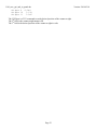
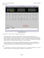
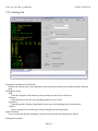
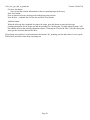
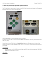
1101_mcc_gui_and_to_panel.doc Version: 2014-03-18 TO Panel MCC Graphic User Interface TO Hand Paddle A Reference for the Telescope Operators. Page 1 1101_mcc_gui_and_to_panel.doc Version: 2014-03-18 1. Introduction ......................................................................................................................................................... 3 2. The TO (Telescope Operator’s) Panel ................................................................................................................ 4 3. MCC GUI............................................................................................................................................................ 6 3.1 General Layout.............................................................................................................................................. 6 3.2 Main Buttons ................................................................................................................................................. 6 3.3 MCC main tabs ............................................................................................................................................. 6 3.4 GUI CLI interface ......................................................................................................................................... 7 3.5 Notices dialog window ................................................................................................................................. 7 3.6. MCC1 TAB.................................................................................................................................................. 8 3.7. MCC2 Tab ................................................................................................................................................. 16 3.8. MCC3 Tab ................................................................................................................................................. 19 3.9. Balance Tab ............................................................................................................................................... 21 3.10. Pointing Tab ............................................................................................................................................. 25 3.11. Details Tabs ............................................................................................................................................. 27 4. The TO (Telescope Operator’s) Hand Panel .................................................................................................... 28 Page 2 1101_mcc_gui_and_to_panel.doc Version: 2014-03-18 1. Introduction The TO Panel is a hardware panel located in the operator area. This panel is use by the operator and provide hardware based input to the TCS3. The MCC GUI (Master Control Console) is an X11 Windows-based application running on the TCS3 computer (hostname t1). This provide the Graphic User Interface for the Operator. Normally two copies are running on the TCS3 duel monitors located at the TO area. Up to five copies can be running at once. Normally, only the two TO copies of the GUI should be running. The TO Hand Paddle is a hardware panel located in the operator’s area. This hand paddle provide some offset and pointing map buttons. Page 3 1101_mcc_gui_and_to_panel.doc Version: 2014-03-18 2. The TO (Telescope Operator’s) Panel The TO Panel is physically attached to the tcs3 system via a cable into the T3 Servo Electronic box. It is located in the Telescope Operators Area. It provide numerous safety and convenience items for the operator. 2.1 Lockable safety switches The following 3 safety controls are located with in the upper-left cover. These are safety controls that can be lock (using the key). Dome Control – 3 position switch to select dome control mode: Locked – Software will not allow any movement (MCC GUI and Dome Handpaddle locked out). Handpaddle – Only the Dome handpaddle will control the dome’s movement (software is locked out). Software – Dome control via the MCC GUI is enabled (Dome Handpaddle is locked out). Limit Override – ON (Green LED is on) mean to override the hardware stop & brake limits for the HA & Dec axis. Telescope Enable – OFF to disable HA,DEC AMP and engage telescope brakes. ON to allow servo control. Telescope enable should be OFF when the TCS Servo is not used. 2.2 Other Safety Controls Emergency Stop – Press to disable Telescope & Dome movements via the safety board. Mirror Cover Emergency Close – Open the normally operation mode, as mirror covers are control via the MCC GUI. In an Emergency (and the TCS software in inoperable), setting the switch to close will close the mirror covers. Page 4 1101_mcc_gui_and_to_panel.doc Version: 2014-03-18 There are 3 switch to control the max velocity of the telescope. There are 2 velocity limits in the tcs: 400 as/s, and 1600 as/s. Automatic/Unsafe – When in Automatic , velocity of 1600 as/s is allow. When in unsafe, 400 as/s is the velocity limit, unless overridden by the One Shot or Supervised switch. Supervised – During some moves (ie: slewing), the velocity limit can be raised to 1600 as/s by depressing this momentary switch. The ideal is the TO are to visually ‘supervised’ the telescope when pressing this switch. One Shot Supervised and Supervised can be pressed together to allow the 1600 as/s limit for the duration of the move. The Automatic & One Shot can be secured using the eyelet, allowing only the Supervised high speed moves. Safety Board OK LED will be on when there are no latched errors on the safety board. System Power LED is on when the system power is ON. Brake ON LED is on when the HA & Dec brake are ON. 2.3 Remaining Controls The TO Joystick is a self-centering 2 axis joystick. It is used for error adjustment during tracking, and velocity adjustment during MV moves. Review track and MV servo modes for MCC1. During tracking the TO Joystick’s can be used to adjust the pointing map in NSEW or Spiral mode. The toggle switch to the right of the joystick enables you to control this mode. The Floor light control the dimmer for the Dome floor light. This hardware contol is independent of the computers. The Dome Light (Off/On) control the dome florescence light via the tcs3 software. The Humidity LED display the relative humidity (0 to 100%). Page 5 1101_mcc_gui_and_to_panel.doc Version: 2014-03-18 3. MCC GUI The MCC GUI (Master Control Console) is an X11 Windows-based application running on the TCS3 computer (the computer t1). It provides the Graphic User Interface for the Operator. Normally two copies are running on the TCS3 duel monitors located at the TO area. Up to five copies can be running at once (for example, another computer displayed via Max). Normally, only the two copies of the GUI should be running. 3.1 General Layout The GUI application has 3 main sections: Main Buttons MCC main tabs MCC CLI (command line interface) 3.2 Main Buttons At the top of the MCC GUI, the following Main Buttons appear: About – brings up an ‘about’ dialog box. FB0 to FB6 – the GUI provides six Function Buttons. Function buttons can execute tcs commands stored in a text file. To associate a text file with a function button, you would enter the command: m.SetButton # $PATH $FILENAME. For example: m.SetButton 0 /home/tcs3/data/mcc_macros zenith would set FB0 to run the file “zenith” from path “/home/tcs3/data/mcc_macros”. The FB0 button would then execute it. Hints: To make a macro file assignment permenant, place it in the ~/current/to/main/mcc/.mcc-init file. Stop – cancel the currently executing macro file. Notices – Brings up the ‘Notices’ popup dialog window for controlling sounds related to warning notices (see 2.1.4). Quit – exits the GUI 3.3 MCC main tabs The GUI is organized as a set of tabs on the main window. Each tab will be covered in a separate section in this document. Mcc1 Mcc2 – Mostly concerned with the HA, Dec, Dome and shutter control. – General facility IO and show next object buffers. Page 6 1101_mcc_gui_and_to_panel.doc Version: 2014-03-18 Mcc3 – Less frequently used MCC widgets. Balance – Counter weight control Pointing – Pointing Map related widgets. Details – Provides access to engineering screens which display many internal TCS3 variables. 3.4 GUI CLI interface This is the GUI Command Line Interface (CLI). Here you can manually enter tcs commands. First put your mouse cursor in the CLI area, then type in commands. Some status data also appears in the output window. 3.5 Notices dialog window When the ‘Notices’ button on the main window is pressed, a dialog popup appears which allows control of sounds associated with the warning notices which are displayed in the mcc1 Warnings window. The dialog looks like: The entries in the dialog box correspond to the list of possible error and warning notices that can be displayed in the ‘Warnings’ display area on the mcc1 window (see 2.2.4). If the check box to the left of an entry has a check in it, then if that message is activated in the ‘Warnings’ display an associated sound will be played about every 15 seconds. Uncheck the box to deactivate the sound associated with that notice message. Once the dialog box is visible, it can be dragged to any location on the desktop. To hide the dialog box, click the ‘Hide’ button at the bottom of the box. Page 7 1101_mcc_gui_and_to_panel.doc Version: 2014-03-18 3.6. MCC1 TAB The MCC1 tab primarily contains widget that are concerned with the telescope, dome, and shutter positioning. Also some safety and warning indicators are located here. Time & Position display On the top, the sky RA, HA, Dec, and their non-sidereal rates are display in yellow text. The the right, the time is display in HST, UTC, and the Sidereal Time. There are 2 diagram to represent the HA and Dec axis. Note the HA diagram is using East-to-the-left display convension. • The larger yellow arrow is the current desired telescope position. • The larger gray arrow should the actual position of the servo (often covered by the yellow arrow). • The mangenta line indicated where the software limit are. • The inner dial show the speed of the axis using an arrow and text in arcsec/sec. Page 8 1101_mcc_gui_and_to_panel.doc • • Version: 2014-03-18 The yellow bars below the diagram indicate the AMP command voltage to each of the 2 motor for each axis. The APE position is display in cyan, along with the difference of the APE and IE (incremental encoder). The ‘Misc’ box in this display contains other positional and environmental information. Dome/Shutter display & control This window contains 3 sections: Dome Feedback • The blue circle/dome show the azimuth of the slit. The Dm AZ: is the Dome’s slit azimuth. North is on top and East (90 deg Az) is on the left. • The yellow arrow show the azimuth of the telescope. Err: shows (obs_az – dome_az). • The Operator Inputs list some IO setting important to dome control: state of the Brakes; DAC output to the dome amps (volts), and the velocity of the dome (deg/sec). • The IO Output show state of brakes, DAC (Amplifier input voltage), and dome velocity (in deg/sec). Shutter Feedback • The yellow arrow show the telescope’s elevation, on the blue side view of the dome/slit. • The blue shows a side view of the dome and illustrates the shutter’s open position. The shutter opening is divided in to 3 segments. The meaning of the the top and bottom segments are: o Zenith to 1.125 Air mass (ZD 90 to 27.3 degrees) would be the area covered by the lower shutter when it is in its highest position (ULimit + Touch). o 1.5 Air mass to bottom (ZD 48 to 70 degrees) show the position of the lower shutter when it is down (DLimit) • The magenta line illustrate is where the Horizontal hardware limits is (approx ZD of 70 degrees). • The bottom has indicator for Upper Shutter UP (ULimit), Shutters Touching (Touch) , and Lower Shutter Down (DLimit) shutter switches. Dome/Shutter control widgets. • For software dome control to work, you much select Software on the Dome_Cnlt=Software on the TO Panel. • The Dome Software Modes are : Lock, Manual, Auto, Goto. o Lock – Software will not attempt to move the dome. o Manual – using the widget provided, the operator has full manual control of the dome. The slider allows you to control the range to apply of the dome amps, ie: 0.5 is half range (5V), 1.0 is full range (10V). The buttons will command the dome to move left, right, or stop. o Auto – Auto mode will attempt to position the dome at the current telescope’s Azimuth. o Goto – Allows the operation to enter the destination azimuth for a dome move. • Shutter control – 2 sets of button are used to control the upper & lower shutter. Select Open or Close to move the appropriate shutter cart. You must click and continue holding the mouse during the move. Releasing the mouse button will stop the operation. Limits display This display shows the status of various limit switches, the system brakes, and system power. Page 9 1101_mcc_gui_and_to_panel.doc Version: 2014-03-18 A grid showing the state of the Slew, Software, Stop, and Brake limits for each axis (N, S, E, W), and the state of the Horizon Slew and Stop. These GUI’s LED will blink with the limits are ON. Override Software limits = Override toggle on MCC2 GUI is checked. Override Hardware limits = Override limit switch on TOP is ON. Telescope at Zenith = Both the HA and DEC hardware ‘Zenith’ indicator is ON. Platform not stowed = platform under the telescope warning. Closed-cycle cooler off = Cooler is off warning. Primary mirror color on = Air blowing across the primary mirror warning. Brake Off/On – indicates the state of the servo (HA/Dec) brakes. Sys Pwr On – indicates the state of switch line power. Servo This window show the current servo mode. Steps for operation each servo mode is provide. Servo - Stop – When the servo mode is STOP, the pmac PID loop is disabled (open Loop mode), and the brakes are ON. To exit stop mode, select another mode. Stop mode means the servo is OFF. Brakes are On. The label “TOP Telescope Enable is OFF/ON” indicates the state of the telescope enable switch on the TO Panel. When operator is not present in the TO area, this should be OFF to prevent remote uses from running the TCS. Function you can perform in Stop mode: • APE.Set.PMAC – The command initializes the position in the PMAC motor controller using the current APE position, or “Apes set the PMAC”. This should be done at zenith at the start of the observing night. Page 10 1101_mcc_gui_and_to_panel.doc • • Version: 2014-03-18 SafetyBrd.Reset – Sents a reset to the TCS3 safety board. When the safety board has errors, they are latched until the errors are cleared. Once cleared, you can resume servo operation. This button issues the safety board reset command. Hello TCS3 – A button that plays a sound file. Servo - MP – MP is Move Position. This mode allows the operator to move to a HA Dec absolute position. To perform an MP move: • Click on the MP radio button to enter MP mode. • Enter your HA, Dec destination position, and velocity, OR • Press the buttons on the right (Top Ring Down, Stow, Zenith) to auto fill the HA, Dec destination positions with a pre determined position. • Click on Execute MP Move to begin. While in MP: • The Servo window displays the status of the current move. • The velocity is limited to 400 as/s unless the OneShow, Safe or Supervised buttons are used to allow high speed moves. • You can enter new HA, Dec, Vel values and press Execute MP Move while a move is in progress. To stop an MP move: • Press the Stop MP Move button Servo - MV – MV is Move Velocity. This mode allows the operator to move the telescope by specifying a velocity for each axis. Page 11 1101_mcc_gui_and_to_panel.doc Version: 2014-03-18 Enter the MV mode by clicking on the Servo Mode’s MV radio button. You can now control the velocity using 3 methods: Joystick, DomeHP, or GUI. All inputs are used simultaneously. Joystick: • Enable the TO Joystick. (and Disable DomeHP). • Enter your desired rate. • Use the TO Panel’s Joystick to change the velocity. Dome HP • Enable the DomeHP (and disable Joystick). • Enter your desired rate. • Use the dome hand paddle N,S,E,W buttons to move the telescope. GUI • • • • Disable both the Joystick and DomeHP. Enter a HA and Dev velocity. Press ‘Execute MV’ to set telescope velocity. Press ‘Stop’ to set velocity to 0. In the status area, the following information is displayed. • The requested velocity is the sum of the Software + Joystick + domeHP inputs. The PMAC velocity is the commanded velocity to the motor controller. The bar graph displays to actual motor’s velocity. • The OneShot, Safe, and Supervised labels are colored GREEN or Gray to reflect the state of these TOPanel switches. • Software label will be green if the rates are enter via the GUI, below show the requested rates in “/s. Enabling the Joystick or Dome Handpaddle will set the Joystick ON or DomeHP On labels green. If any buttons are pressed to command a velocity the ‘N S E W’ char will turn green. Page 12 1101_mcc_gui_and_to_panel.doc Version: 2014-03-18 Servo - Track – Track mode tracks the RA and Dec target position. To start tracking: • Click on the track radio button. • The position table (display in the feedback window) is used to determined the target position. While Tracking: • Position and offsets are display on the top left. Various rates (and other information ) is display on the right. • The performance of the RTCS and servo system (Motors) are summaries in “Servo Performance”. The status should always be “Good” or “OK”. o Good RTCS status means the commanded position to the PMAC matches the VTCS. o Good PMAC performance means the motor servo error is less that 0.1 arcseconds. • The “Pointing Map” status shows key map variables. o MAdj is the MapAdjustment register (Map adjustments preserved during slews) o Corr is the total from the Peak, Spiral, and Rates registers. o The pointing rates are shown, but group with other telescope rates. o The Spiral Position (in rotation) is also displayed. • The lower-right status area has miscellaneous data o The ‘MeaWgt=’ label identifies the current value for the measurement widget. The measurement widget allow you to measure offset and Pointing map movement without needing to clear either the offset or pointing map. Use the ‘mw.z’ tozero the values. • Beam Switch controls include: o ‘A’ button – switch to beam A. Page 13 1101_mcc_gui_and_to_panel.doc • • • Version: 2014-03-18 o ‘Set’ button & RA/Dec offset spin buttons– Pressing ‘Set’ will set the beam offsets to these values loaded in the spin box numeric inputs. o ‘B’ button – switch to beam B. ‘Slew to’ includes: o Slew 0 – Slews to next object #0 (see MCC2’s next object list). o Slew 1 – Slew to next object #1. o etc ‘Rates’ controls – allow setting the non-sidereal rate (ns.rate) and the pointing map rate (pt.rate). o To set the non-sidereal rate, enter the RA and Dec values using the spin buttons, and press ns.rate to issuing the ‘ns.rate RA DEC’ command. o To set the pointing map rate, enter the RA and Dec values using the spin buttons, and press pt.rate to issuing the ‘ps.rate IH ID’ command. Pointing buttons include: o Update– Issues the ‘pt.madj’ command to transfers correction (peak, spiral, rates) to the MAdj register. The MAdj registers hold IH, ID values that are saved from slew to slew. o Save – Does a ‘pointing update and saves the IH/ID values to disk to be restored when starting the IC, or when doing a Last( pt.restore). o Last – Restore the MAdj values saved to disk with ‘pt.restore. o Pt.clear – Clears the Corr pointing registers (Pt.peak, pt.spiral, and pt.rates). o mw.zero - This ‘measurement widget zero’ button zeros the values display by the ‘MeaWgt=’ label. To stop Tracking: • Enter another servo mode, for example, STOP. Servo - Slew – The Slew mode slews to a RA and Dec sky position. The can only be started while Tracking, and when the slew is done, Tracking resumes. A slew is initiated from the tracking screen. Once the telescope is slewing this screen appears. Page 14 1101_mcc_gui_and_to_panel.doc Version: 2014-03-18 The status area display the estimated time to completion. The setting of the OneShot, Safe, and Supervised buttons are display. The HA/DEC velocity and Distance Left are display using a bar graph and text. • • Slew.Abort – Aborts the current slew. The current position is loaded into the tracking table’s base, and tracking resumes. ReSlew – Re commands the PMAC to slew. Due to a bug, some times the slew doesn’t move the telescope (sits there with 0 velocity). Press this button to re-command the slew. Once the slew is done, the TCS will automatic start tracking. Warning display This window is used to display error and warning notices. A sound is associated with each notice, and the sounds may be controlled by the ‘Notices’ dialog (see 2.1.4). If the error or warning condition no longer exists, the message(s) will be cleared from the screen. Notices are displayed in order of importance. In this sample display, warning notices are shown that indicate a counterweight stuck during a balance operation and that the current humidity level matches or exceeds the humidity warning threshold as currently set. Both of these conditions will cause a warning sound to be played every 15 seconds. In this sample display, the same warnings are active as in the previous example, but the ‘Notices’ dialog has been used to deactivate the sounds associated with the humidity warning. This is indicated by the red symbol to the left of the warning text (an ‘S’ with a line through it). Page 15 1101_mcc_gui_and_to_panel.doc Version: 2014-03-18 3.7. MCC2 Tab Motor Currents: Ha, Dec, and Dome motor currents are displayed. For HA and Dec, the yellow graphs show the differences of the motors (scaled up by 2 x) Operators need to monitor this while tracking to insure the telescope is in balance. Mirror covers: Select ‘Shut’ or ‘Open’ to close or open the mirror covers. The bottom label provide feedback on the position. Mirror Support: The voltage for monitoring the mirror pressure is displayed. Below the voltage, use the mirror.support OFF/On button to turn off/on the air support. The label to show the current state of the air support control (Off or ON). This button issues the mirror.support command. You muse be at Zenith for this command to execute. The OK / FAULT label indicates the condition of the Kill_Support IO line. If Air Support is off due to a hardware error, the FAULT label is shown. You must clear the hardware fault, then press the Page 16 1101_mcc_gui_and_to_panel.doc Version: 2014-03-18 ‘Fault.Ack’ button to return on an OK status. Then you may turn on Mirror Support (using the OFF/On button) Collimate: To change collimation, you must have the collimation enabled by checking the enable checkbox. Use the slider to set the desired increment value for the + and – buttons. Click on the ‘E’, ‘W’, ‘N’, or ‘S’ button to change the desired collimation position The Goto or desired position is shown in the Text Entry widget. You can also enter the desired postion in the text widget ( remember to hit return) to specify the desired dpos. The actual position, or apos, is shown next to the label ‘Actual’. Green text indicated the actual position in within range of the desired position, otherwise the value is displayed in red. On the bottom, a label show with secondary (chopper or hexapod) is currently in use. Collimate/Focus Table: The collimate table provides up to 10 preset collimation and focus positions for various instruments. To set the collimation using the table: 1. Enable Collimation and Focus 2. Click a button in collimation table. This will set the collimation and Focus Dpos to values stored in the table, and the collimation should move to this new position. The button’s Text colors provide the following information: Green = Collimation Desired Position match this entry in the collimation table. Black = This entry’s position doesn’t match the current collimation’s dpos. Gray = This is a unused table entry (text should say ‘unused’). The data in the collimation table is read from /home/to/data/collimation.txt. Using a text editor you can update the entries in this file, or add new items. More detailed instruction on how to edit the collimation table is located the in 1201_Operators_Guide. This file is read when the IC is started. To re-read the file, type ‘collimate.table.read’ in the CLI interface. The FIOC Details display should the collimation table data for tcs3. Mirror Cooling There are 2 widget for Mirror Cooling: 1) A radio button to set the mirror cooling mode to off, manual, or auto. Selecting the radio button will issue the mc.mode command to the TCS. 2) A label to show a status string. This is a short description on the mirror cooling status, some example are: “MC is OFF” – summary of mc.mode off (Fan OFF, Heater OFF, Actuator at 0 volts) “Manual Mode. Fan=On Heat=Off Act=10.0v” – summary of manual mode. The default setting for manual mode is for the cooling to be ON. “AUTO and cooling ON.” – Mc.mode is Auto, and cooling is ON ( Fan ON, Heater OFF, Actuator at 5 volts). “AUTO. Defrost 99%” – Mc.mode is Auto, but in Defrost mode (Fan OFF, heater ON, Actuator 0 volts), the percent indicate how long you are in the defrost cycle (about 30 minutes long). “AUTO but cooling OFF” – mirror is below set point. For detail status on the mirror cooling, see the Detail Tab, and view FIO_MC on the MCC GUI. For addition documentation on mirror cooling see the TCS3 Design Documents T3-315x in http://irtfweb.ifa.hawaii.edu/~tcs3/tcs3/Design/document_index.html. Laser Traffic: These widget provide frequently used Laser Traffic options. When Lct.Enable is ON, the system should write the telescope position to the web site. The Ltc.impact checkbox when check will set IMPACT=YES. Page 17 1101_mcc_gui_and_to_panel.doc Version: 2014-03-18 Focus: This is the chopping secondary focus control , disable the focus when not using the chopper. You can set the desire focus position by editing the “Goto” value. Either enter the value in the text entry area, or use the -/+ button to increment the desired position. The slider at the bottom controls the increment amount. This Goto value will update if the desired position is changed. The Actual label show the actual position of the focus mechanism in volts as sampled by the TCS A/D. The text will be RED until the focus moved to the desired position. The Focus.Enable check button, until Enable or Disables the software control loop to move the focus mechanism. The Focus.Adj.Enable determine if the focus adjustment value is added to the user_dos to determine the desired postion. If the tcs see the apos is not changing when commanded to move, a Focus_Stuck warning is display on MCC1. Misc: Hum.wn – This slider widget sets the Humidity Warning level. The page values is set to 5. Wind.wm – This slider sets the High Wind Warning value in MPH. The page value is set to 5. Software Limit Override – Toggles the Sw.limits.override Off or On. When checked, software limits are ignored. See MCC GUI’s Details -> Position table for value of various limits. Hor Slew Limit Override – Toggles the HSlew.Limit.Override Off or On. When checked, the horizon slew hardware limit which limits velocity to 400 as/s is ignored. Next Object List: Display the next object list. The tcs3 ‘Next’ command allow users to send slew request positions to the tcs. This request are display here. To slew to one of the item on the list use the ‘Slew N’ command, where N is a value from 0 to 5. If a proper motion is in excess of 10 arcseconds per year, the PM values are colored red. Bad proper motion value had been sent to the TCS, this warning will help flag potential bad slew destinations. System Power – Turns off or On the system power. Macro Dialog Box: To the right the macro dialog box is available. Text files of TCS3 commands can be execute by selecting, the pressing the Exec button. The directory contains the macro files is print at the top of the macro box. You can use a text editor / file manager to inspect/maintain these files. Page 18 1101_mcc_gui_and_to_panel.doc Version: 2014-03-18 3.8. MCC3 Tab Motor Currents: Ha, Dec, and Dome motor currents are displayed. For HA and Dec, the yellow graph shows the differences of the motors (scaled up by 2 x) Hand Paddles: Options for each physical TCS3 hand paddles. Each hand paddle that has a N,S,E,W button has a set of widget to control the following properties: Enable – Off/On to disable or enable hand paddle inputs. Swap E/W – swap the E/W directions on the hand paddle. Swap N/S – swap the N/S directions on the hand paddle. Rate (as/s) – enter the velocity applied with the hand paddle’s NSEW buttons. ‘E W N S ‘ – these label indicate the status of the handpaddle button: Black=off; Green=ON or pressed. The TOHP, also has the following labels to indicate the status of the following inputs (Black=off; Green=on): X5 = 5x rate switch. BS = beamswitch request button Offset = pointing (off) or offset (On) adjustment mode. Gotobase = goto base request button Engineering Options and PID Page 19 1101_mcc_gui_and_to_panel.doc Version: 2014-03-18 Item in these window are engineering option. Daycrew/TOs should not change them unless directed by the TCS3 technical support staff. Vtcs.offset.opt – controls how the offset are added to the base, resulting in the target destination for tracking. Hist_ON –Use this check box to enable/display the recording of the tcs History Data, 10 sec buffer of various TCS3 servo information at 20Hz.. This data is display in the Details tab’s Perf-T and Perf-G displays. Hist.Save – This button will write the contents of the History Data Buffers to the History Directory. This History Data Buffer hold 10 sec of various servo variables, sampled at 20Hz. The following widget are not documented in this manual. Again see the tcs3 programmer for details. They should not be changed by the daycrew or TO unless directed by the TCS programmer. ServoOpt.Enable AutoPID Track.NoIOnOffset.HA Track.NoIOnOffset.Dec Hexapod.Init – This button is request the fio_hexe run the hexapod init script. This script initializes the hexapod. However, this can also be accomplished using the hexeGUI, plus the HexeGUI provide better feedback that the TCS. Page 20 1101_mcc_gui_and_to_panel.doc Version: 2014-03-18 3.9. Balance Tab Common elements appearing on the manual and auto mode screens: Motor Currents: Ha, Dec, and Dome motor currents are displayed. For HA and Dec, the ‘d’ show the differences of the motors. CW.Enable checkbutton Click to enable or disable counterweight control. CW Mode dropdown menu Select either the manual or auto mode. Status Window displaying counterweight status information such as the enable status and any current counterweight movement in progress. Auto Mode: Auto Mode Screen ‘UP’, ‘DOWN’, ‘EAST’,’ WEST’, ‘NORTH’, ‘SOUTH’ buttons [auto mode]: Page 21 1101_mcc_gui_and_to_panel.doc Version: 2014-03-18 Clicking these button will changed the Desired Position of the counterweights. The Actual Position is displayed on the widget. After changing the DPos, position display changes to Red and display both the desired and actual in this format, 0.00 >> 1.00. When the DPos has been reached, the display returns to black. An ‘(S)’ in the position display indicates the counterweight is stuck – it has stop moving but has not reached it desired position. An ‘(L)’ indicates it has reached a limit set in the software and can not be moved further in auto mode. Notes: The numbers next to each counterweight name refers to the counterweight numeric ID. If counterweights are not enabled, the brakes are on, or the power is off, a warning message will appear in the status window. Because the voltage indicating counterweight position fluctuates slightly, the test for reaching the desired position does must allow for this. This may result in the counterweight stopping at a position which does not exactly match the desired position voltage. . Increment Slider used to set the amount of voltage increment added or subtracted by each click on an ‘UP’, ‘DOWN’, ‘EAST’, ‘WEST’, ‘NORTH’, or ‘SOUTH’ button. Balance Files Counterweight position settings may be saved and restored as named files. The current save path is shown above the file list window. Executing a position file will load in the saved position for each counterweight, and the TCS will cycle through the counterweights to moving each one into positions. To save a set of counterweight positions, enter a file name in the file entry box and click the ‘Save As’ button. To execute a saved file, click on the file in the list and then click the ‘Exec’ button. The ‘Refresh’ button relists the files in the balance file directory. The directory path man be changed by the “CW.Dir” command (see the 1101_command user’s manual document). The default CW.dir is “/home/tcs3/data/cw”. By convention, the files are named using these rules: 1st name is capital, showing the instrument in the center of MIM. Upto 3 names show what else is installed in the MIM. Last part is the day the file was created in MMDDYY. Name and date separted by “_”. For example, this name “CSHELL_spex_hipwac_8wnm_020906” was created with CSHELL in the middle, and spex, hipwac, 8wnm installed on the MIM. Balance was done on Feb 09, 2006. The content of the file is: CW.Dpos 1 4.015 CW.Dpos 2 6.310 CW.Dpos 3 1.275 CW.Dpos 4 1.264 CW.Dpos 5 -4.966 CW.Dpos 6 -5.015 CW.Dpos 7 -0.819 CW.Dpos 8 -0.905 Page 22 1101_mcc_gui_and_to_panel.doc Version: 2014-03-18 CW.Dpos 9 -2.248 CW.Dpos 10 5.158 CW.Dpos 11 5.066 The CW.Dpos is a TCS command to set the desired position of the counter weight. The 2nd field is the counterweight numeric ID. The 3rd field is the desired position of the counter weight in volts. Page 23 1101_mcc_gui_and_to_panel.doc Version: 2014-03-18 Manual Mode: Manual Mode screen ‘UP’, ‘DOWN’, ‘EAST’, ‘WEST’, ‘NORTH’, ‘SOUTH’ buttons: These buttons operate as in the auto mode to control the direction of movement for the selected counterweight, however in the manual mode the + or – control voltage will be applied for as long as the button is selected or until the counterweight hits a hard limit. In the manual mode only the actual position voltage is displayed, without the direction arrows, ‘(S)’ or ‘(L)’ indicators. The minimum and maximum position limits for each counterweight are displayed in [ ] in its button labels. One other difference between the auto and manual modes is that some of the counterweights may be operated as linked pairs. This is implemented by the wide buttons linking pairs of counterweights. For example, The wide UP(+) under TVF(3) and TVF(4) move both counterweight up. Note: A warning appears in red in the status window if the mirror cover is closed, the system power is off, or the brakes are on since these will impact dynamic balancing (see screen shot above). Page 24 1101_mcc_gui_and_to_panel.doc Version: 2014-03-18 3.10. Pointing Tab Pointing File Settings and Coefficients: Displays the current values of the parameters associated with a pointing run and the pointing correction map. Pointing File Setup: Path: Enter the full path for the directory where pointing run data file is to be stored. Filename:. Enter the name for the file where pointing run data is to be stored. Separation: Enter the number of degrees separation between stars in the pointing array to be generated. Caption: Enter a caption to be stored as part of the pointing file header information. Open File button Press to create and open the pointing file and to write out the header information to the file. Pointing Run Control: Page 25 1101_mcc_gui_and_to_panel.doc Version: 2014-03-18 Get Next Star button Press to load the position information for the next pointing target in the array. Slew Next button: Press to start the telescope slewing to the loaded target star position. Next & Slew – combines the Get Net Star and Slew Next buttons. Add Star button: When the telescope has completed slewing to the target, press this button to store the telescope pointing information for the target star into the pointing file. Checking the ‘Do Map Adjust (Pt.map)’ will also add the offset to the pointing adjustment register. Checking the ‘Do Next & Slew’ will (after saving the data), get the Next Star and start the Slew. The pointing run procedures are documented in document 1201_pointing_run.doc under the tcs3 user’s guide. Follow these procedure when doing a pointing run. Page 26 1101_mcc_gui_and_to_panel.doc Version: 2014-03-18 3.11. Details Tabs The details tab provide access to engineering screens where the detailed information on the TCS3 can be viewed. To be used by the technical staff for trouble shooting. The individual items are not covered in this document, only a summary of the available engineering displays are listed: Pos Time Graph1 Graph2 PMAC App FIOA FIOB FIOC FIOD FIOE FIOF FIOMC FIOX Astronomy and servo motor positional data. Time and other VTCS informaiton variables. Performace graphs for TCS, mostly show server performance.. Performace graphs for TCS, has motor current, collimation, focus, and guider corrections.. The PMAC motor control details. Internal TCS3 & MCC process and application data. Facility IO device fioa details. Facility IO device fiob details Facility IO device fioc details Facility IO device fiod details Facility IO device fioe details. Facility IO device fiof details. Facility IO device for the Mirror Cooling IO. Facility IO details for misc processes: Dome Serial input process details. Fio_ape process details. Laser Traffic Control details. IQUP Wind Speed details. Queries to smokey (IRTF Guider). Page 27 1101_mcc_gui_and_to_panel.doc Version: 2014-03-18 4. The TO (Telescope Operator’s) Hand Panel The TO Hand Panel is attach to the tcs3 system via the FIOCD box. It provides some buttons for offsetting and point map control. Here a photo of the hand paddle: TO Hand Paddle (Top View) TO Hand Paddle (Front-side). The TO Hand Paddle is to be used while the telescope is tracking. To activate it, go to the MCC3 GUI and check the enable in the TOHP box. Also enter your desired rate in the rate (“/s) prompt.. On the front side of the TOHP, there is a Pointing/Offset slider switch. This sets the mode of some of the buttons on the top face to either pointing or offset. The N, S, E, W, and Go To Base button are affected by this mode setting: Pointing Mode: In pointing mode, the N, S, E, W buttons will adjust the IH/ID values for the pointing map. The Go To Base button is equivalent to a pt.save. Offset Mode: Page 28 1101_mcc_gui_and_to_panel.doc Version: 2014-03-18 In offset mode, the N, S, E, W buttons will adjust the UserOS values. The Go To Base button will set the UserOS to 0,0. The Beam Sw. button will toggle the Beam Position. The N/S Swap switch will swap the direction of the N and S buttons. The E/W Swap switch will swap the direction of the E and W buttons. The 5 X Rate slider will set the rate to 5 times the rate set in the mcc3 GUI’s rate value for the TOHP. Page 29