1
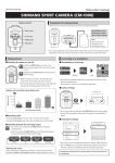
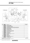
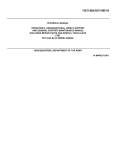
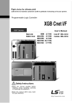
DURA-ACE Bar End Shifting Lever
SL-BS79
10-Speed
For Front Lever
For Rear Lever
4
4
5
5
3
3
2
2
S7
2
3
4
5
6
SHIMANO
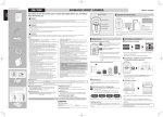
CODE NO.
Y-6RP 02000
Y-65A 24200
Y-6J6 01000
Y-643 43010
Y-6RP 50000
Y-6RP 49000
Y-628 90010
Y-86B 22000
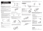
DESCRIPTION
Lever Fixing Screw (M5 x 19) for Rear
Lever Fixing Screw (M5 x 17) for Front
Lever Boss Cover for Rear
Lever Boss Cover for Front
Lever Axle
Body Fixing Bolt
Segment Unit
Outer Cable Guide
A: Same parts.
B: Parts are usable, but differ in materirals, appearance, finish, size, etc.
Absence of mark indicates non-interchangeability.
SL
-B
SL
-B
ITEM
NO.
*
1
*
4
6
8
6
1
S6
1
INTERCHANGEABILITY
A
A
A
A
A
A
0811-2873A
General Safety Information
WARNING
In order to realize the best performance, we
recommend that the following combination be used.
DURA-ACE
Series
– To avoid serious injuries:
• Obtain and read the service instructions carefully
prior to installing the parts. Loose, worn or damaged
parts may cause the bicycle to fall over and serious
injury may occur as a result. We strongly recommend
only using genuine Shimano replacement parts.
• Read these Technical Service Instructions carefully,
and keep them in a safe place for later reference.
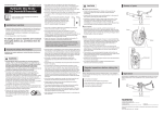
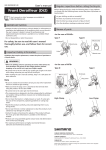
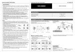
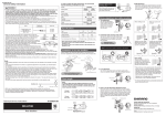
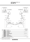
3. Install the lever to the body unit.
Shifting lever
SL-BS79
Rear derailleur
RD-7900
FD-7900
Front derailleur
SP41 sealed outer casing
Outer casing
1.2 mm dia. (stainless steel)
Inner cable
SM-SP17
Bottom bracket guide
Tightening torque:
2.5 - 3 N·m {21 - 26 in. lbs.}
10
Sprockets
Lever grip
Note
• For smooth operation, use the specified outer casing
and bottom bracket cable guide.
• Because the high cable resistance of a frame with
internal cable routing would impair the SIS function,
this type of frame should not be used.
• The sliding surfaces of the inner cable and outer
casing should be greased before use.
• The shifting lever can be installed to handlebars with
diameters of 19.0 – 22.0 mm.
• Operation of the levers related to gear shifting should
be made only when the front chainwheel is turning.
• Parts are not guaranteed against natural wear or
deterioration resulting from normal use.
• For any questions regarding methods of handling or
maintenance, please contact the place of purchase.
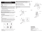
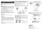
Installation of the lever
When installing the components to carbon frame/handle
bar surfaces, verify with the manufacturer of the carbon
frame/parts for their recommendation on tightening torque
in order to prevent over tightening that can cause damage
to the carbon material and/or under tightening that can
cause lack of fixing strength for the components.
Set so that the
projection faces
downward.
Right: Thickness
(large)
Left: Thickness
(small)
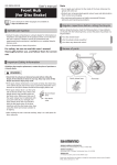
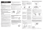
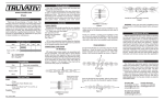
4. Install the outer casing stopper to the brazed-on boss.
Brazed-on boss (M5)
Stopper fixing bolt
3 mm Allen key
The illustration shows an explanation of the case where
the shifting lever is installed to drop handlebars.
Install the front lever in the same way.
1. Attach the body unit to the handlebar, and then use a 5
Outer casing stopper (SM-CS50)
mm Allen key to turn the body fixing bolt
counterclockwise to tighten it.
Tightening torque:
1.5 - 2 N·m {13 - 17 in. lbs.}
Tightening torque:
5 - 6 N·m {43 - 52 in. lbs.}
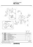
5. With the outer casing placed along the handlebar, cover the outer casing with
Technical
Service Instructions
SL-BS79
the outer casing guide, and then use tape or similar material to provisionally
attach it to the handlebar.
SI-6RP0A-001
Bar End
Shifting Lever
Body fixing bolt
Outer casing guide
Body unit
5 mm Allen key
2. Install the lever boss to the body unit.
One Holland, Irvine, California 92618, U.S.A. Phone: +1-949-951-5003
Tape
Industrieweg 24, 8071 CT Nunspeet, The Netherlands Phone: +31-341-272222
3-77 Oimatsu-cho, Sakai-ku, Sakai-shi, Osaka 590-8577, Japan
Please note: specifications are subject to change for improvement without notice. (English)
© May 2008 by Shimano Inc. XBC SZK Printed in Japan.
Lever boss
6. Wrap the handlebar with bar tape.