Transcript
User's manual
UM-24N0E-004-00
Quick Release
(for Disc Brake)
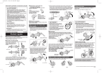
Quick Release function
When the quick release lever is brought to the closed position, the lever nut moves
inward. The force of this clamps the wheel to the frame and holds the wheel securely in
place.
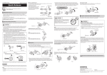
3. Grip the fork with your fingers and use the palm of your hand to close the quick
release lever with as much strength as possible. When closed, the quick release lever
must be in the "CLOSE" position shown below in the diagram on the right. The side of
the lever with the inscription "CLOSE" must be facing away from the bicycle, and the
lever should be parallel to the fork as shown below in the diagram on the left.
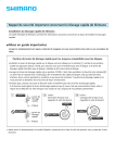
Positioning of the quick release lever
For safety, the quick release lever should be along the bicycle frame when in the CLOSE
position.
CLOSE position
Tightening torque:
5 -7.5 N·m {43 -65 in. lbs.}
Adjusting nut
User's manuals in other languages are available at :
http://si.shimano.com
Fork
CLOSE position
Quick release
lever
Lever nut
Open position
IMPORTANT NOTICE
Quick release lever
• Contact the place of purchase or a bicycle dealer for information on installation and
adjustment of the products which are not found in the user's manual. A dealer's
manual for professional and experienced bicycle mechanics is available on our website
(http://si.shimano.com).
Front
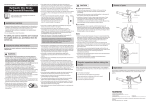
Removing the wheel
Move the quick release lever from the CLOSE position to the OPEN position.
Loosen the adjusting nut, and then remove the wheel.
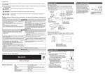
The clamping strength is adjusted by turning the adjusting nut. When the nut is turned
in a clockwise direction, the clamping strength increases, and when the nut is turned in a
counter-clockwise direction, the clamping strength decreases.
Weaker
• Do not disassemble or alter this product.
Adjusting
nut
For safety, be sure to read this user's manual thoroughly
before use, and follow them for correct use.
CAUTION
Stronger
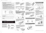
Never fasten a wheel to a frame by rotating the
quick release lever as shown in the diagram on
the right.
Simply rotating the lever in a circular motion will
not fasten the wheel to the frame.
Detachment of the wheel as a result of improper
hub installation can result in serious bodily injury.
Important Safety Information
Guidelines that require replacement, contact the place of purchase or a bicycle dealer.
OPEN position
Suitable dimensions of the fork end
WARNING
Be sure to use only fork widths with suitable dimensions.
• This wheel is equipped with a quick release hub to facilitate installation and removal.
Failure to properly install this quick release hub (wheel) onto your bicycle may cause
the wheel to become detached from the bicycle while you are riding and result in
serious bodily injury.
• Use a front fork which is equipped with a wheel retention mechanism.
Front ...
cannot use fork thicknesses less than
4 mm.
(Dura-Ace, 600 Ultegra: not less than
5 mm.)
Regular inspections before riding the bicycle
Rear ...
cannot use fork thicknesses less than
5 mm.
(Dura-Ace, 600 Ultegra: not less than
6 mm.)
• BEFORE USE, CAREFULLY READ THE QUICK RELEASE USER'S MANUALS IN YOUR
OWNER'S MANUAL. IF YOU HAVE ANY QUESTIONS, ASK YOUR DEALER. IMPROPER
HUB INSTALLATION CAN RESULT IN SERIOUS BODILY INJURY.
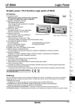
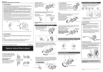
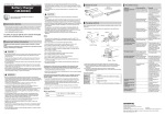
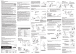
• If the quick release lever is on the same side as the rotor, the quick release lever may
fail to have sufficient clearance as shown in Figure 1.
If the quick release lever interferes with the rotor, install the lever on the other side of
the rotor.
Make sure that the front fork does not interfere with the quick release lever.
Adjust the quick release lever within the range specified in Figure 2.
Interference of the lever with the front fork may loosen the wheel, thereby causing
the wheel to become detached from the bicycle while you are riding and result in
serious bodily injury.
Figure 1
Rear
Quick release
lever
Figure 2
Forward
direction
Before riding the bicycle, check the following items. If any problems are found with the
following items, contact the place of purchase or a bicycle dealer.
Note
If the quick release lever can be easily pushed to the CLOSE position, this means the
clamping strength is insufficient. Return the quick release lever to the position
perpendicular to the bicycle frame and again turn the adjusting nut clockwise to increase
the clamping trength. Push the quick release lever back to the CLOSE position.
WARNING
THINGS TO CHECK BEFORE RIDING
1. Always check your quick release hubs before riding to make sure that the wheels
are correctly installed on the bicycle frame. This is especially important after you
park your bicycle in a public place.
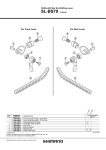
Operation
The front axle is explained as an example. The rear axle works in the same way.
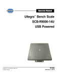
How to fasten this quick release hub
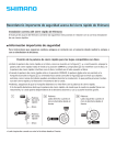
1. Move the quick release lever to the OPEN position and set the wheel so it firmly
touches the interior of the fork end (See sketch below).
Adjusting nut
2. Make sure that the quick release levers are
pushed fully to the CLOSE position (the
side of the lever with the inscription
"CLOSE" must be facing away from the
bicycle).
As shown in the diagram the lever must
be lifted, not rotated.
CLOSE position
OPEN position
If the clamping strength is adjusted too strong and the quick release lever cannot be
pushed to the CLOSE position, turn the adjusting nut in a counter-clockwise direction to
reduce the clamping strength. When doing this, do not fully release the adjuster nut.
Turn it 1/8 of a revolution, and then try to push the lever to CLOSE,
to set the maximum clamping strength with which you can push the quick
release lever to the CLOSE position.
OK
Rotor
Not OK
• After reading the user's manual carefully, keep it in a safe place for later reference.
NOTICE
• Be sure to operate the quick release lever by hand only. Never use any other tool such
as a hammer to tighten the quick release lever, as this could cause damage to the
lever.
Note
• Products are not guaranteed against natural wear and deterioration from normal use
and aging.
OPEN position
OK
No Good
2. Open and close the quick release lever with your right hand while gradually
tightening the adjusting nut with your left hand in the clockwise direction. Continue
tightening the nut until you feel resistance with your hand at the point when the
lever is parallel to the hub (as indicated by the dotted position in the diagram on the
right).
• For maximum performance we highly recommend Shimano lubricants and
maintenance products.
Turn 1/8 revolution at
a time
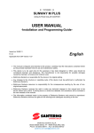
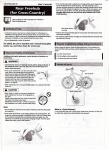
QUICK CHECK
Lift up the bicycle so that the wheel is off the
ground, and give the top of the tire a few
sharp downward blows as shown in the
diagram. The wheel should not be loose or
come off. This check does not guarantee that
the quick release lever has received adequate
tightening torque.
If you are uncertain as to whether the quick
release is tightened correctly, repeat the
installation procedure as explained in "How
to fasten this quick release hub" of this user's
manual.
If the quick release will not adjust properly, please contact a professional dealer for
advice.
What is a Quick Release?
It is a mechanism that uses a single quick release lever operation on the hub to enable
the wheel to be easily installed and removed.
Adjusting nut
Quick release lever
One Holland, Irvine, California 92618, U.S.A. Phone: +1-949-951-5003
Industrieweg 24, 8071 CT Nunspeet, The Netherlands Phone: +31-341-272222
3-77 Oimatsu-cho, Sakai-ku, Sakai-shi, Osaka 590-8577, Japan
Please note: specifications are subject to change for improvement without notice. (English)
© May 2012 by Shimano Inc. HTR SZK