1
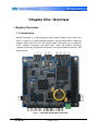
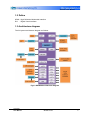
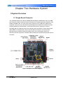
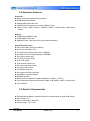
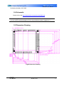
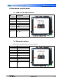
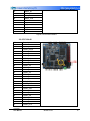
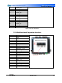
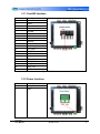
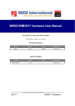
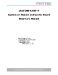
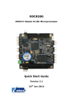
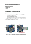
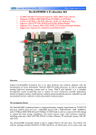
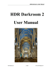
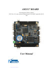
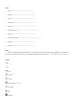
SOC8200 User Manual SOC8200 Hardware User Manual Version of 1.0 Release: 2010-07-10 SOC8200 User Manual Version of 1.0 SOC8200 User Manual Revision history Rev Date Description 1.0 2010-07-10 Initial version SOC8200 User Manual Version of 1.0 2 SOC8200 User Manual Thank you for purchasing our products, we will do better because of you. Embest Info&Tech Co., LTD. Room 509, Luohu Science&Technology Building, #85 Taining Rd., Shenzhen, Guangdong, China 518020 Tel: +86-755-25635656/25636285 Fax: +86-755-25616057 Email: [email protected] http://www.embedinfo.com/english http://www.armkits.com SOC8200 User Manual Version of 1.0 3 SOC8200 User Manual DIRECTORY SOC8200 HARDWARE USER MANUAL ....................................................................... 1 CHAPTER ONE: OVERVIEW ......................................................................................... 5 I SYSTEM OVERVIEW .......................................................................................................... 5 1.1 Introduction ................................................................................................................ 5 1.2 Define ......................................................................................................................... 6 1.3 Architecture diagram .................................................................................................. 6 CHAPTER TWO HARDWARE SYSTEM ........................................................................ 7 II SYSTEM OVERVIEW ......................................................................................................... 7 2.1 Single Board Computer.............................................................................................. 7 2.2 Hareware Features .................................................................................................... 8 2.3 Electric Characteristic ................................................................................................ 8 2.4 Schematic................................................................................................................... 9 2.5 Dimension Drawing .................................................................................................... 9 III HARDWARE SPECIFICATION ........................................................................................... 10 3.1 USB host & USB Interface ....................................................................................... 10 3.2 Network interface ..................................................................................................... 10 3.3 Camera Interface ..................................................................................................... 11 3.4 MMC Interface.......................................................................................................... 11 3.5 UART1 Interface ...................................................................................................... 12 3.6 Analog IO Interface .................................................................................................. 12 3.7 Digital IO Interface ................................................................................................... 13 3.8 TFT_LCD Interface .................................................................................................. 13 3.9 PC104 Interface ....................................................................................................... 14 3.10 Multifunctional Expansion Interface ....................................................................... 17 3.11 Can/485 Interface ................................................................................................... 18 3.12 Power Interface ...................................................................................................... 18 3.13 UART(TTL) Interface.............................................................................................. 19 3.14 JTAG Interface ....................................................................................................... 19 APPENDIX ..................................................................................................................... 20 APPENDIX I EXPANSION BOARD OVERVIEW ....................................................................... 20 APPENDIX II FUNCTION INTERFACE BOARD........................................................................ 22 EMBEST TECHNICAL SUPPORT AND WARRANTY SERVICE.................... 23 TECHNICAL SUPPORT SERVICE ........................................................................ 23 MAINTENANCE SERVICE CLAUSE ..................................................................... 23 BASIC NOTICE TO PROTECT AND MAINTENANCE LCD ............................ 24 VALUE ADDED SERVICES ..................................................................................... 25 SOC8200 User Manual Version of 1.0 4 SOC8200 User Manual Chapter One: Overview I System Overview 1.1 Introduction Embest SOC8200 is a highly-integrated single board computer with PC104 form factor. It employs TI’s high-performance AM3517 microcontroller which is based on 600Mhz ARM Cortex-A8 Core with NEON SIMD Coprocessor and POWERVR SGX™ Graphics Accelerator and offers video, image, and graphics processing capable of supporting single board computers, home and industrial automation, and digital signage. Fig 1-1 SOC8200 Single Board Computer SOC8200 User Manual Version of 1.0 5 SOC8200 User Manual 1.2 Define HDMI : High Definition Multimedia Interface DVI : Digital Visual Interface 1.3 Architecture diagram The full system architecture diagram as follows: Fig1-3 SOC8200 architecture diagram SOC8200 User Manual Version of 1.0 6 SOC8200 User Manual Chapter Two Hardware System II System Overview 2.1 Single Board Computer The SOC8200 board has onboard 256MB DDR2 SDRAM, 256MB Nand Flash and 4MB Nor Flash and extends various functions through pins including serial port, Ethernet, CAN, RS485, SD/MMC card, CF card, Audio In/Out, Camera, LCD, USB Host, USB Device, expansion connector and JTAG. Embest has designed an expansion board and function interface boards for the SOC8200. It would be convenient for customer to use the SOC8200 with the expansion board for evaluating the functionality of Texas Instruments' Sitara AM3517 microprocessor. And in the later period customer can add functions through function interface boards according to their own requirements which can effectively shorten the period of research and development of products and speed up time to market. Fig2-1 SOC8200 Connection Diagram SOC8200 User Manual Version of 1.0 7 SOC8200 User Manual 2.2 Hareware Features Processor AM3517 industrial applications processors NEON SIMD Coprocessor 600MHz ARM Cortex-A8 Core POWERVR SGX Graphics Accelerator (AM3517 only) 16KB I-Cache, 16KB D-Cache, 256KB L2-Cache, 112KB ROM, 64KB Share SRAM Memory 256MB DDR2 SDRAM, 32bit 256MB NAND Flash, 8bit 4MB NOR Flash, 16bit (driver has not provided at present) Signals Routed to Pins One 5-wire Debug serial port (RS232) One 5-wire serial port (TTL) Two USB 2.0 Host High-speed ports, 480Mbps One USB 2.0 Device High-speed port, 480Mbps One channel Audio input Two channel Audio output 16-bit LCD output 10-bit Camera video input One channel S-Video output One channel AV output One RS485 serial port One channel CAN bus interface 10/100Mbps network interface SD/MMC interface Multi-functional expansion interface (McBSP, IIC, McSPI, TV-OUT) PC104 expansion interface (GPMC Bus, MMC, USB, McSPI, UART1, Clock, HDQ) JTAG interface 2.3 Electric Characteristic SOC8200 Single Board Computer Dimensions: 96mm*90mm (8 layer PCB design) Input voltage: +5V Power Consumption: About 3W Working Temp.: -40℃~85℃ SOC8200 User Manual Version of 1.0 8 SOC8200 User Manual Working Humidity: 20%~90% 2.4 Schematic Please refer to the http://www.armkits.com/product/soc8200.asp Warning: The schematic is only used for customer reference, if customers want to use it for their own development, we do not provide any technic support on it. 2.5 Dimension Drawing Fig2-5 Dimension Drawing SOC8200 User Manual Version of 1.0 9 SOC8200 User Manual III Hardware specification 3.1 USB host & USB Interface PIN Description 1 OTG_DM 2 OTG_DP 3 OTG_BUS 4 OTG_ID 5 U1_DM 6 U1_DP 7 GND 8 POWER_USB 9 U2_DM 10 U2_DP Fig3-1 USB host & USB device Interface 3.2 Network interface SOC8200 is 10M/100M adaptive network interface PIN Description 1 GND 2 VCC_IO 3 TXN 4 TXP 5 GND 6 RXN 7 RXP 8 LED2/NINTSEL 9 LED1/REGOFF 10 GND Fig3-2 Network Interface SOC8200 User Manual Version of 1.0 10 SOC8200 User Manual 3.3 Camera Interface PIN Description 1 GND 2 CAM_D0 3 CAM_D1 4 CAM_D2 5 CAM_D3 6 CAM_D4 7 CAM_D5 8 CAM_D6 9 CAM_D7 10 CAM_D8 11 CAM_D9 12 GND 13 CAM_PCLK 14 GND 15 CAM_HS 16 CAM_VS 17 VCC_IO 18 IIC3_SDA 19 IIC3_SCL 20 GND Fig3-3 Camera Interface 3.4 MMC Interface PIN Description 1 VCC_IO 2 MMC1_CLK 3 MMC1_CMD 4 MMC1_D0 5 MMC1_D1 6 MMC1_D2 7 MMC1_D3 8 MMC1_CD 9 MMC1_WP 10 GND SOC8200 User Manual Version of 1.0 11 SOC8200 User Manual Fig3-4 MMC Interface 3.5 UART1 Interface PIN Description 1 N/A 2 N/A 3 R1IN 4 T2OUT 5 T1OUT 6 R2IN 7 N/A 8 N/A 9 GND 10 N/A Fig3-5 UART1 Interface 3.6 Analog IO Interface PIN Description 1 CH7 2 CH6 3 CH5 4 CH4 5 CH3 6 CH2 7 CH1 8 CH0 9 GND 10 VCC_IO Fig3-6 Analog IO Interface SOC8200 User Manual Version of 1.0 12 SOC8200 User Manual 3.7 Digital IO Interface PIN Description 1 CH7 2 CH6 3 CH5 4 CH4 5 CH3 6 CH2 7 CH1 8 CH0 9 GND 10 VCC_IO Fig3-7 Digital IO Interface 3.8 TFT_LCD Interface PIN Description 1 GND 2 DSS_CLK 3 DSS_HS 4 DSS_VS 5 GND 6 N/A 7 DSS_D11 8 DSS_D12 9 DSS_D13 10 DSS_D14 11 DSS_D15 12 GND 13 DSS_D5 14 DSS_D6 15 DSS_D7 16 DSS_D8 17 DSS_D9 18 DSS_D10 19 GND 20 N/A SOC8200 User Manual Version of 1.0 13 SOC8200 User Manual 21 DSS_D0 22 DSS_D1 23 DSS_D2 24 DSS_D3 25 DSS_D4 26 GND 27 DSS_DEN 28 VCC_IO 29 VCC_IO 30 N/A 31 N/A 32 Y+ 33 X- 34 Y- 35 X+ 36 LCD_PEN 37 VCC_5V 38 LCD_ADJ 39 GND 40 N/A Fig3.8 TFT_LCD Interface 3.9 PC104 Interface 3.9.1 PC104-64 PIN Description 1 GND 2 N/A 3 VCC_5V 4 VCC_5V 5 VCC_IO 6 VCC_IO 7 GND 8 SYS_RST 9 POWER_RST 10 SYS_CLKOUT2 11 SYS_CLKOUT1 12 HDQ_SIO 13 SYS_32K SOC8200 User Manual Version of 1.0 14 SOC8200 User Manual 14 GND 15 IRQ 16 GPIO58 17 GPIO57 18 GPIO56 19 GPT11 20 GPT10 21 GPT9 22 IIC1_SDA 23 IIC1_SCL 24 GND 25 UART4_RX 26 RS485_TXEN 27 RS485_RXEN 28 UART4_TX 29 GND 30 MCBSP4_DX 31 MCBSP4_DR 32 MCBSP4_CLKX 33 MCBSP4_FSX 34 MCBSP_CLKS 35 GND 36 GPIO157 37 GPIO162 38 SPI4_CS0 39 SPI4_SOMI 40 SPI4_SIMO 41 SPI4_CLK 42 GND 43 SPI1_CS3 44 SPI1_CS2 45 SPI1_SOMI 46 SPI1_SIMO 47 SPI1_CLK 48 GND 49 MMC2_D7 50 MMC2_D6 51 MMC2_D5 52 MMC2_D4 53 MMC2_D3 54 MMC2_D2 SOC8200 User Manual Version of 1.0 15 SOC8200 User Manual 55 MMC2_D1 56 MMC2_D0 57 MMC_CMD 58 MMC2_CLK 59 GND 60 U3_DP 61 U3_DM 62 U4_DM 63 U4_DP 64 GND Fig3-9-1 PC104-64 Interface 3.9.2 PC104-40 PIN Description 1 GND 2 GPMC_NCS4 3 GPMC_NCS3 4 GPMC_NCS2 5 GPMC_A10 6 GPMC_A9 7 GPMC_A8 8 GPMC_A7 9 GPMC_A6 10 GPMC_A5 11 GPMC_A4 12 GPMC_A3 13 GPMC_A2 14 GPMC_A1 15 GPMC_NBE1 16 GPMC_WAIT3 17 SYS_RST 18 GPMC_CLE 19 GND 20 GPMC_ALE 21 GPMC_CLK 22 GPMC_WE 23 GPMC_OE 24 GPMC_D15 25 GPMC_D14 26 GPMC_D13 27 GPMC_D12 SOC8200 User Manual Version of 1.0 16 SOC8200 User Manual 28 GPMC_D11 29 GPMC_D10 30 GPMC_D9 31 GPMC_D8 32 GPMC_D7 33 GPMC_D6 34 GPMC_D5 35 GPMC_D4 36 GPMC_D3 37 GPMC_D2 38 GPMC_D1 39 GPMC_D0 40 GND Fig3-9-2 PC104-40Interface 3.10 Multifunctional Expansion Interface PIN Description 1 GND 2 TV_OUT1 3 GND 4 TV_OUT2 5 GND 6 VCC_IO 7 GND 8 MCBSP2_CLKX 9 MCBSP2_FSX 10 MCBSP2_DR 11 MCBSP2_DX 12 IIC2_SDA 13 IIC2_SCL 14 GND 15 SPI2_CLK 16 SPI2_SIMO 17 SPI2_SOMI 18 SPI2_CS0 19 SPI2_CS1 20 GND Fig3-10 USB_HOSTInterface SOC8200 User Manual Version of 1.0 17 SOC8200 User Manual 3.11 Can/485 Interface PIN Description 1 CANH 2 CANH 3 CANL 4 CANL 5 CHGND 6 CHGND 7 RS485A 8 RS485B 9 RS485Z 10 RS485Y 11 MCBSP2_DX 12 IIC2_SDA 13 IIC2_SCL 14 GND 15 SPI2_CLK 16 SPI2_SIMO 17 SPI2_SOMI 18 SPI2_CS0 19 SPI2_CS1 20 GND Fig3-11 RS232 Interface 3.12 Power Interface PIN Description 1 VCC_5V 2 GND SOC8200 User Manual Version of 1.0 18 SOC8200 User Manual Fig3-12 Power Interface 3.13 UART(TTL) Interface PIN Description 1 VCC_IO 2 GND 3 UART2_CTS 4 UART2_RTS 5 UART2_TX 6 UART2_RX Fig3-13 UART (TTL) Interface 3.14 JTAG Interface PIN Description 1 VCC 2 TMS 3 TDI 4 NTRST 5 TD0 6 RTCK 7 TCK 8 EMU0 9 EMU1 10 GND Fig3-14 JTAG Interface SOC8200 User Manual Version of 1.0 19 SOC8200 User Manual Appendix Appendix I Expansion Board Overview The customer can evaluate the AM3517 via SOC8200 expansion board, to experience the AM3517 processor, The customer can use single board computer and function Interface board to add the product functions, thus reducing product development cycles, achieve faster time to market. SOC8200 Development Board SOC8200 Expansion Board Audio/Video Interface Audio input port Stereo audio output port 15-pin standard VGA output interface SOC8200 User Manual Version of 1.0 20 SOC8200 User Manual Buzzer Communication Interface One 5-wire RS232 serial port (DB9) One 9-wire RS232 serial port (DB9) One 9-wire TTL serial port (2*5pin 2.5mm pitch connector) Two High-speed USB 2.0 Host ports, 480Mbps One High-speed USB 2.0 Device port, 480Mbps One 10/100Mbps Ethernet port (RJ45) 10-bit Camera interface Reset button SD/MMC card slot CF card slot Electric Characteristic SOC8200 Expansion Board Dimensions: 170mm*190mm SOC8200 User Manual Version of 1.0 21 SOC8200 User Manual Appendix II Function Interface Board In order to facilitate rapid customization of products, Embest launch function interface board based on SOC8200 Single Board Computer, to make the every function modulization. Each module can be built up through the copper pillar and then through the cable connected to the SOC8200 single board computer. ECOM-4 & ECOM-8 Remark: We do not supply function interface boards for SOC8200 retail orders except bulk orders. SOC8200 User Manual Version of 1.0 22 SOC8200 User Manual Embest Technical support and Warranty Service Embest Info&Tech Co.,LTD., established in March of 2000, is a global provider of embedded hardware and software. Embest aims to help customers reduce time to market with improved quality by providing the most effective total solutions for the embedded industry. In the rapidly growing market of high end embedded systems, Embest provides comprehensive services to specify, develop and produce products and help customers to implement innovative technology and product features. Progressing from prototyping to the final product within a short time frame and thus shorten the time to market, and to achieve the lowest production costs possible. Embest insists on a simple business model: to offer customers high-performance, low-cost products with best quality and service. The cotent below is the matters need attention for our products technical support and warranty service: Technical support service Embest provide one year free technical support service for all products from Embest. Technical support service covers: Embest embedded platform products software/hardware materials Assist customers compile and run the source code we offer. Solve the problems accurs on embeded software/hardware platform if users follow the instructions in the documentation we offer. Judge whether the product failure exists. Special explanation, the situations listed below are not included in the range of our free technical support service, and Embest will handle the situation with discretion: Software/Hardware issues user meet during the self-develop process Issues happen when users compile/run the embedded OS which is tailored by users themselves. User’s own applications. Problems happen during the modification of our software source code Maintenance service clause 1. The products except LCD, which are not used properly, will take the warranty since the day of the sale: SOC8200 User Manual Version of 1.0 23 SOC8200 User Manual PCB: Provide 12 months free maintenance service. 2. The situations listed below are not included in the range of our free maintenance service, Embest will charge the service fees with discretion: A. Can’t provide valid Proof-of-Purchase, the identification label is tour up or illegible, the identification label is altered or doesn’t accord with the actual products; B. Don’t follow the instruction of the manual in order to damage the product; C. Due to the natural disasters ( unexpect matters ), or natural attrition of the components, or unexpect matters leads the defects of appearance/function; D. Due to the power supply, bump, leaking of the roof, pets, moist, impurities into the boards, all those reasons which lead the defects of appearance/function; E. User unauthorized weld or dismantle parts leads the product’s bad condition, or let other people or institution which are not authorized by Embest to dismantle, repair, change the product leads the product bad connection or defects of apperance/function; F. User unauthorized install the software, system or incorrect cofiguration or computer virus leads the defects; G. Purchase the products through unauthorized channel; H. Those commitment which is committed by other institutions should be responsible by the institutions, Embest has nothing to do with that; 3. During the warranty period, the delievery fee which delivery to Embest should be coverd by user, Embest will pay for the return delivery fee to users when the product is repaired. If the warranty period is expired, all the delievery fees will be charged by users. 4. When the boards needs repair, please contact technical support department. Note: Those products are returned without the permission of our technician, we will not take any responsibility for them. Note: Embest do not supply maintenance service to LCDs. We suggest the customer first check the LCD after get the goods. In case the LCD can not run or no display, customer should inform Embest within 7 business days from the moment get the goods. Basic notice to protect and maintenance LCD SOC8200 User Manual Version of 1.0 24 SOC8200 User Manual Do not use finger nails or hard sharp object to touch the surface of the LCD, otherwise user can’t enjoy the above service. Embest recommend user to purchase a piece of special wiper to wipe the LCD after long time use, please avoid clean the surface with fingers or hands to leave fingerprint. Do not clean the surface of the screen with chemicals, otherwise user can not enjoy above service. Value Added Services We will provide following value added services: Provided services of driver develop base on Embest embedded platform, like serial port, USB interface devices, LCD screen. Provided the services of control system transplant, BSP drivers develop, API software develop. Other value added services like power adapter, LCD parts. Other OEM/ODM services. Technically training. Please connect Embestl and get technical support: Support Tel:+86-755-25503401 Fax:+86-755-25616057 Pre-Sale consultation:[email protected] After-Sale consultation: [email protected] SOC8200 User Manual Version of 1.0 25