1
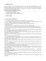
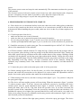
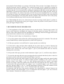
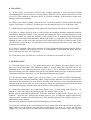
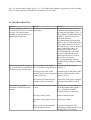
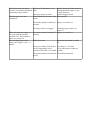
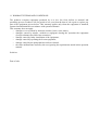
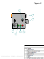
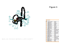
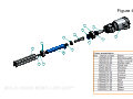
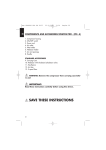
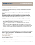
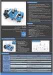
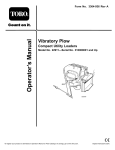
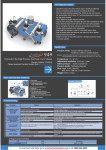
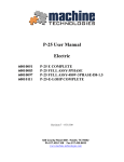
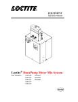
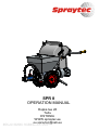
SPR 8
OPERATION MANUAL
Ropka tee 28
Tartu
ESTONIA
WWW.spraytec.ee
[email protected]
1. INTRODUCTION
Spray unit SPR 8 is an airless high-pressure device for spraying of finishing plasters, viscous
paints and adhesives with a maximum grain size of 0.2-0.3 mm. The device can be used to spray
both ready-made putty and putty mixed on-site from powder. The spray unit includes a bag wringer
for emptying of ready-made putty bags.
Benefits of an airless high-pressure spray
• no compressed air is needed;
• less dust is generated while spraying;
• a light and comfortable hose and plaster gun;
• low noise level;
• simple to operate.
2. SAFETY REQUIREMENTS
2.1. You must read the user manual prior to putting the device into operation.
2.2. Only a properly trained operator can use the device. Contact the company that sold you the
device for information about terms and conditions of such training.
2.3. Only a properly trained specialist can perform maintenance of the electrical
system of this device.
2.4. When the device is in operation, no irrelevant persons must be allowed near it.
2.5. The device must be operated in compliance with all requirements listed in this user manual.
2.6. During operation of the device the employees using it must precisely agree on the division of
their functions.
2.7. If the device is not in the same room as the spraying operator, (she)he must be notified about
container filling and other actions performed with the device.
2.8. Only materials specified for the purpose can be used for spraying. If necessary, address your
questions to the material manufacturer.
2.9. Means of protection (goggles, gloves, proper work clothing) must be used when operating the
device.
2.10. Never point the spray gun at people!
2.11. Having completed the work, release pressure from the hose and the spray gun and lock the
spray gun trigger, follow the instructions in the user manual (see point 6.10). Do not leave the
pressurised device unsupervised!
2.12. If the spray tip of the gun becomes clogged, follow the instructions in the user manual (see
point 7.5).
2.13. Prior to putting the device into operation make sure that its hose, spray gun, tip and other
parts are securely attached.
2.14. When connecting the unit to the power supply ensure that all network parameters meet the
requirements stipulated in the user manual and technical data.
2.15. The device can only be connected to the electrical grid using such components that comply
with the manufacturer’s technical specifications. If different standards
are in use, please contact
the product seller.
2.16. In case of an emergency, stop the unit immediately and disconnect the power
cable of the
unit from the power supply.
2.17. Before performing maintenance and repair work the unit must be disconnected from the
power supply.
2.18. For the duration of the device maintenance and repairs you must release pressure from the
hose and the pump (see point 7.5).
2.19. Put the cover on the device container to prevent external items from falling into the
container.
2.20. Clean the device in due time!
2.21. Perform device maintenance and repairs in accordance with the recommendations listed in
the user manual. Address any questions you may have to the seller company.
2.22. When repairing the device, use original spare parts to ensure safe device operation and
preserve its warranty.
2.23. Have the seller company take care of larger-scale repairs.
3. TECHNICAL DATA
Motor
2,2 kW
Electrical requirement
230 V, single phase
Fuse
16 A
Speed
by frequency inverter changeable
Capacity
4-8 l/min
Pump pressure
Max 80 bar
Hose
5/8” 15 m
Nozzle
standard 647
possible 541-651
Container volume
56 l
Length
1200 mm
Hight
950 mm
Width
590 mm
Weight
80 kg
4. STANDARD DELIVERY
1. device SPR8
2. material hose 5/8” 15 m
3. spray gun SP25.000
4. nozzle 647
5. bag wringer
5. DESCRIPTION OF THE UNIT
The housing of the unit is made from stainless steel and the housing of the bag wringer is made
from glass fibre. The materials used ensure long-term durability of the unit. For comfortable
transportation the unit is equipped with large pneumatic tyres and handles, which can be turned
downwards to reduce the overall measures of the unit.
The main assembly units of a plaster spray are the housing of the unit, a transmission system, an
electrical system, a valve system, a hose with a spray gun and bag wringer.
The transmission system consisting of a reduction gear unit, cardan shaft and screw pump with
fastening elements.
The system use a screw pump for generating pressure.
The valve system consisting of a ball valve, a pressure release valve , a manometer and a pressure
sensor.
The pressure sensor starts and stops the unit automatically. The manometer monitors the pressure
of the material.
The electrical system of the unit consists of an electric box with control buttons and a frequency
inverter. A frequency inverter makes it possible to easily adjust the output of the unit.
The function of a bag wringer is to press the ready plaster bags empty.
6. HIGH PRESSURE SYSTEM DEVICE START-UP
6.1. Place the device on a horizontal surface in the area where the work is taking place so that there
is access to the controls on the device and so that it is as convenient as possible to fill the device
with material. When installing the power cable, make sure it isn’t in the way of other employees on
the site.
6.2. Visual inspection of the device
• make sure the hoses are securely fastened;
• make sure there are no unnecessary parts in the material container;
• the reversing switch (figure 2, pos. 3) on the cover of the electric box must be in position 0;
•
turn the speed adjustment knob (figure 2, pos. 2) on the cover of the electricbox to position 50.
6.3. Install the necessary tip on the spray gun. The recommended tips are 645-647-651. Follow the
advice of the manufacturer of the material.
6.4. Fill the container with the material. To empty the bag of putty, turn the bag wringer roller to
the rear position, place the bag on the bag wringer with the bottom toward the roller. Turning the
roller shaft, squeeze the bag end between the roller and the chassis of the wringer. Holding on with
one hand to the bag handle, cut the bag open right underneath the handle. Turning the roller shaft,
squeeze the bag until empty. Turn the roller shaft back into the rear position and remove the empty
bag. Depending on the bag volume, 3-4 bags of material will fit in the container. During the
operation, keep constantly track of the amount of material in the container, and add material if
needed.
6.5. Connect the power cable to the mains power with 16 A line protection.
6.6. Before starting up the device for the first time, as well as after changing the tips, the spray
pressure and switch-off pressure have to be adjusted. It is easier to make the adjustments with two
people. One worker sprays and the other makes the needed adjustments.
6.7. When turning on the device, turn the reversing switch (figure 2, pos. 3) to position 1 and press
the spray gun’s trigger .
6.8. The device will start and the pressure will start rising. When the manometer (figure 3, position
11) shows pressure under 75-80 bar, increase the material’s pressure by increasing the device
rotation speed, turn the speed adjustment knob (figure 2, position 2) slowly clockwise. After
turning the knob, there will be a lag time before the pressure rises. If you have increased the
pressure beyond 80 bar, immediately lower the pressure by turning the knob anti-clockwise. It is
prohibited to operate it at a higher spray pressure than 80 bar, as this will result in very rapid wear
on the screw pump. Keep an eye constantly on the spray pressure (the manometer figure 3, pos. 11)
and if needed, perform an adjustment.
6.9. When you have achieved the right spray pressure, release the spray gun trigger. The device
must switch off immediately at a pressure of 85-90 bar. If the pressure rises higher, the device’s
switch-off pressure must be adjusted. The switch-off pressure can be regulated by turning the
manual nut on the pressure sensor (figure 3, pos. 10). For stabilising the position of the nut there is
a locknut that has to be loosened before making the adjustment, and then secured again after the
adjustment. If you turn the nut clockwise, the device will switch off at a higher pressure, and if you
turn it anticlockwise, the switch off pressure will fall. The pressure adjustment has to be repeated
several times to achieve the optimum result. If you turn the pressure too high, some of the material
will ooze out through the screw pump back into the container. This will increase wear on the pump.
Use of different materials may result in a need to make adjustments.
6.10. When halting the device for a short interval, turn the reversing switch (figure 2, position 3)
into position 0; by pressing the spray gun’s trigger, release the pressure on the system. Lock the
spray gun trigger using the safety.
7. RECOMMENDATIONS FOR SPRAYING
7.1. If the application of the spray becomes uneven, stop the device. Turn the spray nozzle 180
degrees (anti-clockwise) and depress the trigger of the spray gun for an instant. The device will
start up, some of the material will flow through the tip, flushing it. Release the trigger and turn the
spray nozzle back (clockwise) into operating position.
7.2. If the spray nozzle clogs very frequently, try a larger tip.
7.3. Try to keep plaster removed from the wall from getting into the device container. The used and
removed material may contain larger particles, which will clog the tip.
7.4. If the spray pressure is not sufficient for a proper spread, try a smaller tip.
7.5. If the device clogs and also when replacing the tip, there may be a need to decrease the
pressure in the material hose. To do so, use the pressure release valve (figure 3, pos. 22. 23). To
open the valve, unscrew the valve knob (figure 3, pos.23), the material will flow out from the
opening in the valve body.
7.6. Keep track of the spray pressure on the manometer (figure 3 pos.11), and if necessary adjust it.
7.7. In case the unit stops after the spray gun trigger has been released and shortly after re-starts for
a moment by itself, a ball valve must be cleaned (figure 3 pos.20).
Disconnect the unit from the power supply, press the spray gun trigger and let the material under
pressure out from the system. To remove residual pressure remaining in the system, open the
pressure release valve (figure 3, pos. 23). After having ensured that the system is not under
pressure any longer, remove the plaster hose from the unit. Next unscrew the valve (figure 3, pos.
13) and remove the spring from the valve (figure 3, pos. 21) and ball (figure 3, pos. 20). Clean the
ball valve housing (figure 3, pos. 12 ) and all disassembled elements. Check the condition of the
ball and ball seating (figure 3, pos. 15, 16). If needed replace the elements.
In connection with the above the pressure releasing valve should also be cleaned. Unscrew the
pressure releasing valve knob (figure 3, pos. 23) and remove the ball (figure 3, pos. 24). Clean the
valve channels. Assemble the elements in reverse order.
8. CLEANING
8.1. In the course of operation, clean the bag wringer constantly to keep dry material from
accumulating there. It is easiest to use a damp sponge. Keep the exterior surface of the device clean
as well. It is not allowed to clean the device by pressure washing, as the stream of water may
damage electrical components.
8.2. When you are done working, clean the device. Clean the container’s inside walls with a damp
sponge. Pour about a 1 cm layer of clean water on to the material and cover it with plastic film.
8.3. Wash the spray gun tip and tip holder separately. You can place the spray gun’s end in water.
8.4. If there is a longer pause in work (a week or more) the container should be emptied of material
and cleaned. Pump the contents of the container out, unplug the device from the mains power and
wash the container out. Pump the contents of the container out. To keep the pump from getting
stuck, some conservation fluid should be added to the pump, e.g. glycerine. Don’t leave the pump
standing in water, as this will cause corrosion of the motor and it will be very hard to start. In the
case of breaks of several days, it is advisable to leave some material in the device, pour some water
in and cover with film.
8.5. If there is a danger of the device freezing, all of the liquid should be drained from the device.
Hoses can be cleaned with pressurised air. It is recommended to dismantle the pump from the
device and screw the rotor out of the stator.
8.6. From time to time, the ball valve of the device will have to be cleaned (see point 7.7).
9. MAINTENANCE
9.1. The seals (figure 4 pos. 3, 5, 6) on the shaft boot of the reduction gear unit (figure 4 pos. 4)
have to be kept lubricated. The lubrication nipple is located under the electrical box on the
mounting plate of the reduction gear unit (figure 4 pos 1). Use a lubricator. Fill it until you see
lubricant oozing out in the container between the seal and the shaft boot of the reduction gear unit.
Lubrication should be done twice a week. Waterproof lubricants are suitable.
9.2. The pressure sensor (figure 3 pos. 10) hose (figure 3, pos. 9) must be filled with lubricant.
From time to time, lubricant should be added, using the same lubricant you used to lubricate the
shaft boot of the reduction gear unit. Remove the hose from the device, screw the lubrication tool
included with the device into one end of the hose. Pump the lubricant using the lubricator until
clean lubricant emerges from the other end of the hose. Reassemble the hose.
9.3. Axial play between the rotor of the pump (figure 4, pos. 12) and cardan shaft (figure pos. 11)
shall be 2-3 mm. Play can be adjusted by means of a support (figure 4, pos. 7).
Briefly start the unit with an empty tank. To do this, turn the reversing switch (figure 2, pos. 3) to
position 1. Stop the unit. Release the locknut (figure 4, pos. 8) fixing the support and turn the
support so that it touches the end of the rotor. Now turn the support in the opposite direction 1.5
turns and fix with a locknut.
Play has to be adjusted in connection with installing a new screw pump.
9.4. Clean the container before you dismantle the screw pump. Disconnect the unit from the power
supply and release the pressure from the hose and the pump (see point 7.5). Screw out the bolts
(figure 4 pos. 10) and remove the stator housing front (figure 4 pos 2). Remove the rotor (figure 4
pos. 12) and the stator (figure 4 pos. 13). Use a lubricious substance (glycerine) at the assembly
the new stator and rotor. Assemble the elements in reverse order.
10. TROUBLESHOOTING
Problem
Reason
When switching on the device, The rotor of the pump has stuck
the motor has no power to rotate in the stator.
the rotor. The motor makes
attempts to turn and moves for
some degrees and stops.
Actions
Try switching shortly the device
in both directions by turning the
reversing switch (figure 2, pos. 3)
into position 1 and thereafter into
position 2. When an overload
protection activates,
a red signal lamp will switch on
(figure 2, pos. 5). Disconnect the
power cable of the device from
the mains power, wait 10 seconds
and re-connect the cable. Try
starting once again. If after
several attempts the rotor does
not move, demount the screw
pump from the device, clean it,
place in the vise and try
unscrewing manually. During
assembly of the pump use sliding
liquids.
When pressing on the trigger of The reversing switch (figure 2, Turn the reversing switch to
the gun, the device connected to pos. 3) is in the wrong position. position "1".
the mains power will not start.
The plug of the cable of the
Insert the plug of the cable of the
pressure sensor is not connected pressure sensor into the socket
to the electric box.
(figure 2, pos. 7).
The system is pressurised, the
pressure sensor is activated.
The device starts in the
condition of insufficient spray
pressure.
The nozzle of the gun is clogged,
proceed as described in article
7.1.
The rotation speed of the motor Increase the speed by turning the
is slow.
speed adjustment knob (figure 2
pos. 2) clockwise until the
required pressure is achieved.
The spray nozzle is big.
Install a smaller nozzle.
The stator of the pump is worn Install a new stator.
out.
The properties of the material
do not match the device.
Use different material. The
maximum permitted grain size of
the material is 0.2-0.3 mm.
The device starts, the spray
The speed of the motor is too
pressure exceeds the maximum high.
permitted pressure 80 bar.
The spray nozzle is small.
The flat spray yet is not
Little material in the tank of the
continuous.
device.
Reduce the speed of the motor by
turning the knob (figure 2, pos.
2) anti-clockwise.
Install a bigger nozzle.
Add material.
Incorrectly adjusted switch-off Adjust, see article 6.9.
pressure.
The spray nozzle is clogged.
When releasing the trigger of
the spray gun the pressure
increases over the permitted
value, see article 6.9.
The red signal lamp of the
electric box (figure 2, pos. 5)
flashes.
Clean the spray nozzle, see
article 7.1.
Incorrectly adjusted switch-off Adjust, see article 6.9.
pressure.
Difficult to start.
Proceed as described in article
8.6.
The power cables of the device Use cables 3 x 2.5 mm².
are too long and the crossUse as short power cables as
section of the cable is too small. possible.
The material does not match the Use different material.
device.
11. WARRANTY TERMS AND CONDITIONS
The producer warrants equipment produced by it to bee free from defects in material and
producing process. Producer will for period of one year from the date of sale repair or replace any
part of the equipment proven defect. This warranty applies only when the equipment is installed,
operated and maintained in accordance with operation manual.
This warranty does not apply:
– damages or wear caused by abrasion (nozzles, hoses, rotor, stator);
– damages caused by misuse, accident or negligence during the operation the equipment
(foreign substance has fallen into container);
– damage caused by faulty installation of the equipment;
– damage caused by operating the frozen equipment;
– damage caused by the pump that has not been cleaned;
– the other malfunctions caused by the user ignoring the requirements stated in this operation
manual.
Serial no:
Date of sale:
Figure 1
pressure sensor
manometer
lubrication nipple
pressure release valve
support, locknut
Figure 2
3
7
6
2
4
5
1
1
0
2
Figure 3
16 15
25
4
5
17
2
12
10
3
22
9
20
23
11
21
24
18
13 14
6
19
8
7
1
Figure 4
1
4
3
11
14
9
6
5
2
10
12
13
7
8