1
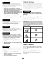
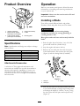
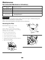
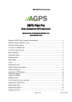
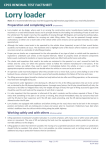
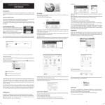
Form No. 3364-936 Rev A
Vibratory Plow
Compact Utility Loaders
Model No. 22911—Serial No. 310000001 and Up
To register your product or download an Operator's Manual or Parts Catalog at no charge, go to www.Toro.com.
Original Instructions (EN)
This product complies with all relevant European
directives, for details please see the separate product
specific Declaration of Conformity (DOC) sheet.
DANGER
There may be buried power, gas, and/or telephone
lines in the work area. Shock or explosion may
occur if you dig into them.
Have the property or work area marked for buried
lines and do not dig in marked areas. Contact your
local marking service or utility company to have the
property marked (for example, in the United States,
call 811 for the nationwide marking service).
Figure 1
1. Model and serial number location
Introduction
Model No.
The vibratory plow is an attachment designed for use on
Toro compact utility loaders to pull flexible pipe and
cable into and through soil. It is designed to be used by
train operators primarily for routing irrigation and utility
lines underground without having to dig a trench for the
entire length of the pipe or cable.
Serial No.
This manual identifies potential hazards and has
safety messages identified by the safety alert symbol
(Figure 2), which signals a hazard that may cause serious
injury or death if you do not follow the recommended
precautions.
Read this information carefully to learn how to operate
and maintain your product properly and to avoid injury
and product damage. You are responsible for operating
the product properly and safely.
Figure 2
You may contact Toro directly at www.Toro.com for
product and accessory information, help finding a
dealer, or to register your product.
1. Safety alert symbol
This manual also uses 2 words to highlight information.
Important calls attention to special mechanical
information and Note emphasizes general information
worthy of special attention.
Whenever you need service, genuine Toro parts, or
additional information, contact an Authorized Service
Dealer or Toro Customer Service and have the model
and serial numbers of your product ready. Figure 1
identifies the location of the model and serial numbers
on the product. Write the numbers in the space
provided.
Contents
Introduction................................................................. 2
Safety ........................................................................... 3
Stability Ratings.................................................... 4
Sound Pressure .................................................... 4
Vibration Level .................................................... 5
Safety and Instructional Decals ............................. 5
Product Overview ........................................................ 6
Specifications ....................................................... 6
Attachments/Accessories..................................... 6
Operation..................................................................... 6
Installing a Blade .................................................. 6
Plowing ................................................................ 7
© 2010—The Toro® Company
8111 Lyndale Avenue South
Bloomington, MN 55420
2
Contact us at www.Toro.com.
Printed in the USA.
All Rights Reserved
Safety
Gauging Plow Depth............................................ 7
Transporting the Plow .......................................... 8
Removing the Plow from the Traction
Unit.................................................................. 8
Operating Tips ..................................................... 8
Maintenance............................................................... 10
Recommended Maintenance Schedule(s) ................ 10
Greasing the Plow .............................................. 10
Servicing the Gear Lube ..................................... 11
Replacing the Coulter ......................................... 11
Storage....................................................................... 12
Troubleshooting......................................................... 13
Improper use or maintenance by the operator or
owner can result in injury. To reduce the potential
for injury, comply with these safety instructions and
those in the traction unit Operator’s Manual. Always
pay attention to the safety alert symbol, which
means Caution, Warning, or Danger—personal
safety instruction. Failure to comply with the
instruction may result in personal injury or death.
DANGER
Contact with the moving plow can cut hands, feet,
or other body parts.
• Keep your hands, feet, and any other part of your
body or clothing away from moving parts.
• Before adjusting, cleaning, repairing, and
inspecting the plow, lower it to the ground,
stop the engine, remove the key, and wait for all
moving parts to stop.
DANGER
There may be buried power, gas, and/or telephone
lines in the work area. Shock or explosion may
occur if you dig into them.
Have the property or work area marked for buried
lines and do not dig in marked areas. Contact your
local marking service or utility company to have the
property marked (for example, in the United States,
call 811 for the nationwide marking service).
WARNING
When the engine is off, attachments in the raised
position can gradually lower. Someone nearby may
be pinned or injured by the attachment as it lowers.
Always lower the attachment lift each time you shut
off the traction unit.
WARNING
When going up or down hill, the machine could
overturn if the heavy end is toward the downhill
side. Someone may be pinned or seriously injured
by the machine if it overturns.
Operate up and down slopes with the heavy end of
the machine uphill. An attached plow will make
the front end heavy.
3
Stability Ratings
WARNING
If you do not fully seat the attachment locking
pins in the attachment mount plate holes, the
attachment could fall off of the traction unit severely
injuring the operator or bystanders.
• Ensure that you fully seat the attachment
locking pins through the holes in the attachment
mount plate before lifting the attachment.
• Ensure that the attachment mount plate is free of
any dirt or debris that may hinder the connection
of the traction unit to the attachment.
• Refer to your traction unit Operator’s Manual
for detailed information on safely connecting an
attachment to your traction unit.
To determine the degree of slope you can traverse with
the plow installed on a traction unit, find the stability
rating for the hill position you want to travel in the
appropriate table below, then find the degree of slope
for the same rating and hill position in the Stability Data
section of the traction unit Operator’s Manual.
WARNING
Exceeding the maximum recommended slope
can cause the traction unit to tip, crushing you or
bystanders.
Do not drive the traction unit on a slope steeper
than the maximum recommended slope, as
determined in the following tables and the traction
unit Operator’s Manual.
WARNING
The plow is very loud during operation; over time,
your hearing may be impaired if unprotected.
Important: If you have a traction unit other than
a TX compact utility loader, use the counterweight
on the traction unit when using the plow. Failure to
use the counterweight will cause the traction unit to
become unstable.
Wear hearing protection during operation.
WARNING
Orientation
Lightning can cause severe injury or death. If
lightning is seen or thunder is heard in the area, do
not operate the machine; seek shelter.
Stability Rating
Front Uphill
C
WARNING
Rear Uphill
When the plow is out of the ground, bystanders
could be injured by the swinging plow, and/or the
traction unit could be overturned by the inertia of
the swinging plow, crushing you or bystanders.
• Keep the plow low at all times.
• Use caution when turning and do not turn
quickly.
• Keep all bystanders at least 6 ft. (2 meters) away
while operating.
D
Side Uphill
C
Sound Pressure
This unit has a sound pressure level at the operator’s
ear of 117 dBA, which includes an Uncertainty Value
(K) of 1 dBA.
CAUTION
Hydraulic couplers, hydraulic lines/valves, and
hydraulic fluid may be hot and can burn you if you
touch them.
• Wear gloves when operating the hydraulic
couplers.
• Allow the traction unit to cool before touching
hydraulic components.
• Do not touch hydraulic fluid spills.
Sound pressure level was determined according to the
procedures outlined in EN ISO 11201.
The sound pressure level will vary depending on
conditions.
4
Vibration Level
Hand-Arm Vibration
Measured vibration level = 7 m/s2
Uncertainty Value (K) = 2.8 m/s2
Measured values were determined according to the
procedures outlined in EN 1032.
100-4650
Whole Body Vibration
1. Crushing hazard of hand—keep bystanders a safe distance
from the machine.
2. Crushing hazard of foot—keep bystanders a safe distance
from the machine.
Measured vibration level = 0.2 m/s2
Uncertainty Value (K) = 0.10 m/s2
Measured values were determined according to the
procedures outlined in EN 1032*.
Safety and Instructional
Decals
Safety decals and instructions are easily
visible to the operator and are located
near any area of potential danger.
Replace any decal that is damaged or
lost.
100-4649
1. Explosion and electric shock hazards—do not dig in areas
with buried gas or electrical lines, keep bystanders a safe
distance from the machine.
5
Product Overview
Operation
Refer to your traction unit Operator’s Manual for more
information on installing and removing attachments
on your traction unit.
Important: Always use the traction unit to lift and
move the attachment.
Installing a Blade
Toro offers several different blades and pullers.
Purchase a blade and puller from your Toro dealer.
Figure 3
1. Vibratory plow body
2. Blade (several optional
blade styles are available)
3. Puller (several optional
puller styles are available)
WARNING
4. Gauge rod assembly
5. Coulter
The blade is sharp and can swing during
installation and removal, cutting, pinching, or
crushing hands or feet.
6. Mounting plate
Wear gloves and work boots and securely hold the
blade.
Specifications
1. Raise the plow about 36 inches (1 m) off of the
ground and install the cylinder lock(s).
Note: Specifications and design are subject to change
without notice.
Width
Length
Height
Weight
Hydraulic motor displacement
Plow cycles
2. Stop the engine and remove the key.
3. Remove the two click pins from the clevis pins
in the blade bracket, then remove the clevis pins
(Figure 4) and the existing blade (if installed).
29 inches (73.6 cm)
35 inches (89 cm)
24 inches (60 cm)
400 lb (181.5 Kg)
1.27 in3/rev (20.8 cc)
2,000 VPM
Attachments/Accessories
A selection of Toro approved attachments and
accessories are available for use with the machine to
enhance and expand its capabilities. Contact your
Authorized Service Dealer or Distributor or go to
www.Toro.com for a list of all approved attachments
and accessories.
Figure 4
1. Click pin
2. Clevis pin
3. Blade
4. Slide the new blade into the blade bracket and secure
it at the desired depth (a change in mounting holes
will change the depth by 3 inches (7.6 cm)), using
the clevis pins and click pins removed previously
(Figure 4).
6
Plowing
CAUTION
1. Move the lynch pins to the outside holes on the
spring rods to allow the plow to move from side
to side (Figure 5).
When plowing on a hill, the plow can swing
down hill when raised out of the soil. Due to
the weight of the plow, if it swings too fast, the
force could tip the traction unit injuring you or
others.
When plowing on a hill, raise the plow out of
the ground slowly, letting it swing while the
bullet is still in the soil.
10. Raise the plow out of the ground far enough to pull
the puller out of the soil.
11. Move the traction unit rearward to pull out a
working length of material, then move forward
slightly to create some slack in the line.
Figure 5
1. Outer hole
2. Lynch pin (in inner hole)
3. Spring rod
12. Stop the engine.
Gauging Plow Depth
CAUTION
Normally, you will be plowing at the maximum depth
set by the blade; however, the plow is also equipped
with a gauge to allow you to lift the plow and determine
how high above maximum depth you are plowing.
When you remove the lynch pin, the plow could
swing into you or a bystander, or cause the
traction unit to become unstable.
The gauge is located on the left side of the plow facing
the traction unit. A rod assembly runs from the gauge
to the ground. When the plow is lifted, the indicator on
the gauge moves down. Marks on the gauge show the
number of inches lower or higher than the maximum
depth that you are plowing. The gauge reads from
+2 to -3 inches (+5 to -7.6 cm), with zero being the
maximum depth on bare ground and -3 being 3 inches
(7.6 cm) above maximum depth. Figure 6 and Figure 7
illustrate the gauge.
Hold the plow in the neutral position when
moving the lynch pins.
2. Connect the material being installed to the plow.
3. If your traction unit has a speed selector, move it to
the slow (turtle) position.
4. Start the engine.
5. Tilt the attachment plate completely back so that the
top of the plow is parallel to the ground (Figure 7).
6. Lower the plow so that it is resting on the ground.
Important: Always ensure that the plow is on
or in the ground before engaging the auxiliary
hydraulics lever. Failure to do so will cause
excessive vibration of the traction unit, possibly
resulting in damage.
Note: If you dig a hole to lower the blade into
before starting, it will reduce the risk of bending
the blade.
Figure 6
7. Pull the auxiliary hydraulics lever to the operator
grip to engage the plow.
1. Depth gauge
8. Slowly lower the plow into the ground to the desired
depth, while moving the traction unit backward.
9. When finished, release the auxiliary hydraulics lever
to stop the plow.
7
2. Gauge locking lever
Removing the Plow from the
Traction Unit
Refer to your traction unit Operator’s Manual for
complete instructions on removing attachments from
the traction unit and disconnecting hydraulic hoses.
1. With the plow raised above the ground, stop the
engine.
2. Remove the lower click pin and clevis pin securing
the blade to the plow (to completely remove the
blade, remove both the upper and lower click and
clevis pins) (Figure 4).
Figure 7
1. Gauge rod assembly
2. Parallel to the ground
3. Swing the blade up and secure it as illustrated in
Figure 8.
When plowing bare ground, maximum depth is
indicated on the gauge as the zero mark. You can
plow down to the +1 mark, but in this case you will be
contacting the ground with the coulter axle. Plowing
any lower may damage the coulter.
When plowing grass covered ground, the gauge will
read about an inch lower than the actual depth because
of the grass. In this case, lower the plow to the desired
coulter depth and note the reading on the gauge.
Figure 8
If you are transporting the plow or are plowing rough
terrain, you can lock the gauge at the +2 position
to keep it from being damaged. To lock the gauge,
manually raise it to the +2 position and move the
locking lever to the left.
1. Stand
2. Coulter
4. Tilt the plow forward and lower it to the ground or
trailer, with the stand and coulter supporting the
weight of the plow (Figure 8).
Transporting the Plow
5. Stop the engine and remove the plow as directed in
your traction unit Operator’s Manual.
1. Move the lynch pins to the inside holes on the spring
rods to prevent side to side movement (Figure 5).
Operating Tips
CAUTION
• Some older model traction units have holes through
the spring and quick attach pins on the mount plate
(Figure 9) to allow you to install two hairpin cotters
when plowing long runs. This will ensure that the
vibration of the plow will not cause the pins to
come loose.
Failure to secure the plow will allow it to swing
side to side and unbalance the plow. Due to
the weight of the plow, if it swings too fast, the
force could tip the traction unit injuring you or
others.
Always secure the plow with the lynch pins
in the inner holes of the spring rods before
transporting the plow.
Note: The quick attach pins on newer traction
units no longer need the hairpin cotters.
2. Raise the loader arms just enough to ensure that the
blade clears the ground.
Important: Never transport the plow with the
arms fully raised.
8
Figure 9
1. Hairpin cotters
• To reduce wear on the traction unit drive chain (if
your model has one), tighten the chain so there is
only 2 inches (5 cm) of slack on the upper span
(refer to your traction unit Operator’s Manual for
instructions).
• Clean the area of trash, branches and rocks before
plowing to prevent equipment damage.
• Always begin plowing with the slowest ground
speed possible. Increase speed if conditions permit,
but do not allow the tires or tracks to spin. Spinning
the tracks or tires will cause turf damage and place
stress on the traction unit.
• Always use full throttle (maximum engine speed)
when plowing.
• Always plow backwards (i.e., in reverse).
• If your traction unit has a speed selector and a flow
divider, move the speed selector to slow (turtle) and
the flow divider to the 10 o’clock position.
• Avoid sharp turns when plowing to increase
productivity and minimize ground disturbance.
• If your traction unit has tires and you have the
agricultural or Sitework Systems tires installed on
the traction unit, remove the tires and move the
right side tires to the left and the left side tires to
the right. This will ensure that the tire tread points
to the rear to give you the most traction when using
the vibratory plow.
9
Maintenance
Recommended Maintenance Schedule(s)
Maintenance Service
Interval
Before each use or daily
Maintenance Procedure
• Grease the plow.
Every 25 hours
• Check the gear lube level.
Every 200 hours
• Change the gear lube.
• Grease the plow.
• Check the gear lube level.
• Paint chipped surfaces.
Before storage
CAUTION
If you leave the key in the ignition switch, someone could start the engine. Accidental starting of the
engine could seriously injure you or other bystanders.
Remove the key from the ignition switch before you do any maintenance.
Greasing the Plow
Service Interval: Before each use or daily
Before storage
Grease 6 fittings, as shown in Figure 10 through
Figure 13, every 8 operating hours. Grease all fittings
immediately after every washing.
Grease Type: General-purpose grease
Figure 11
1. Stop the engine and remove the key.
2. Clean the grease fittings with a rag.
3. Connect a grease gun to each fitting.
4. Pump grease into the fittings until grease begins to
ooze out of the bearings.
5. Wipe up any excess grease.
Figure 12
Figure 10
10
Changing the Gear Lube
Service Interval: Every 200 hours
1. Position the traction unit and plow on a level surface
and lower the attachment lift so that the plow is on
the ground.
2. Stop the engine and remove the key.
3. Prepare an appropriate container to catch the used
oil under the plow.
4. Remove the drain plug (Figure 14), allowing the oil
to spill out into the container.
5. When finished, replace the drain plug, ensuring that
it is tight.
6. Remove the fill plug (Figure 14) and fill the case with
gear lube until it is level with the red dot in the gauge.
7. Replace the fill plug.
Figure 13
Servicing the Gear Lube
Check the gear lubrication oil level in the gear case every
25 operating hours and change it every 200 operating
hours or once a year, whichever occurs first.
Gear lube type: SAE 90-140 API service GL-4 or GL-5
Replacing the Coulter
Refill capacity: 3 pints.
If the coulter becomes excessively worn or damaged,
replace it.
1. Back out the coulter pin screw about 0.5 inch (1.3
cm), then strike it several times with a hammer to
loosen the pin (Figure 15).
Checking the Gear Lube Level
Service Interval: Every 25 hours
Before storage
1. Position the traction unit and plow on a level surface
and lower the attachment lift so that the plow is on
the ground.
2. Stop the engine and remove the key.
3. Check the clear glass gauge on the side of the gear
case (Figure 14). The gear lube should be at the level
of the red dot in the center of the gauge.
4. If the gear lube level is low, remove the fill plug
(Figure 14) and fill the case with gear lube until it is
level with the red dot in the gauge.
Figure 15
1. Coulter pin
2. Coulter
3. Coulter bracket
2. Completely remove the coulter pin screw, washer,
coulter, and coulter pin (Figure 15).
3. Put the new coulter into the coulter bracket
(Figure 15).
4. Slide the coulter pin through the bracket and coulter
and secure it with the coulter pin screw and washer
(Figure 15).
5. Torque the screw to 45 ft-lb (61 N-m).
Figure 14
1. Glass gauge
2. Drain plug
4. Washer
5. Coulter pin screw
3. Fill plug
5. Replace the fill plug.
11
Storage
1. Before long term storage, wash the attachment with
mild detergent and water to remove dirt and grime.
2. Grease the plow.
3. Check gear case lubrication.
4. Check and tighten all bolts, nuts, and screws. Repair
or replace any damaged or worn part.
5. Ensure that all hydraulic couplers are connected
together to prevent contamination of the hydraulic
system.
6. Paint all scratched or bare metal surfaces. Paint is
available from your Authorized Service Dealer.
7. Store the attachment in a clean, dry garage or storage
area. Cover it to protect it and keep it clean.
12
Troubleshooting
Problem
The plow does not operate.
Possible Cause
Corrective Action
1. The hydraulic coupler is not completely
connected
1. Check and tighten all couplers.
2. A hydraulic coupler is damaged.
2. Check the couplers and replace any
that are damaged.
3. Find and remove the obstruction.
3. There is an obstruction in a hydraulic
hose.
4. A hydraulic hose is kinked.
5. The auxiliary valve on the traction unit
is not opening.
13
4. Replace the kinked hose
5. Repair the valve.
Notes:
14
Notes:
15
Toro Compact Utility Equipment Warranty
A One-Year Limited Warranty
Conditions and Products Covered
The Toro® Company and its affiliate, Toro Warranty Company, pursuant
to an agreement between them, jointly warrant your Toro Compact Utility
Equipment (“Product”) to be free from defects in materials or workmanship.
The following time periods apply from the date of purchase:
Items and Conditions Not Covered
Not all product failures or malfunctions that occur during the warranty
period are defects in materials or workmanship. This express warranty
does not cover the following:
•
Product failures which result from the use of non-Toro replacement
parts, or from installation and use of add-on, modified, or unapproved
accessories
•
Product failures which result from failure to perform required
maintenance and/or adjustments
•
Product failures which result from operating the Product in an
abusive, negligent or reckless manner
•
Parts subject to consumption through use unless found to be
defective. Examples of parts which are consumed, or used up, during
normal Product operation include, but are not limited to, digging teeth,
tines, spark plugs, tires, tracks, filters, chains, etc.
•
Contact any Authorized Toro Compact Utility Equipment (CUE)
Service Dealer to arrange service at their dealership. To locate a
dealer convenient to you, access our website at www.Toro.com.
You may also call our Toro Customer Care Department toll free
at 888-865-5676 (U.S. customers) or 888-865-5691 (Canadian
customers).
Failures caused by outside influence. Items considered to be outside
influence include, but are not limited to, weather, storage practices,
contamination, use of unapproved coolants, lubricants, additives, or
chemicals, etc.
•
Normal “wear and tear” items. Normal “wear and tear” includes, but is
not limited to, worn painted surfaces, scratched decals or windows,
etc.
Bring the product and your proof of purchase (sales receipt) to the
Service Dealer.
•
•
Any component covered by a separate manufacturer’s warranty
Products
Loaders, Trenchers and Attachments
Kohler Engines
All other Engines
Warranty Period
1 year or 1000 operating
hours, whichever occurs first
3 years
2 years
Where a warrantable condition exists, we will repair the Product at no cost
to you including diagnosis, labor, and parts.
Instructions for Obtaining Warranty Service
If you think that your Toro Product contains a defect in materials or
workmanship, follow this procedure:
1.
2.
3.
CUE Products
If for any reason you are dissatisfied with the Service Dealer’s
analysis or with the assistance provided, contact us at:
LCB Customer Care Department
Toro Warranty Company
8111 Lyndale Avenue South
Bloomington, MN 55420-1196
Toll Free: 888-865-5676 (U.S. customers)
Toll Free: 888-865-5691 (Canada customers)
Owner Responsibilities
You must maintain your Toro Product by following the maintenance
procedures described in the Operator’s Manual. Such routine
maintenance, whether performed by a dealer or by you, is at your expense.
Parts scheduled for replacement as required maintenance (“Maintenance
Parts”), are warranted for the period of time up to the scheduled
replacement time for that part. Failure to perform required maintenance
and adjustments can be grounds for disallowing a warranty claim.
Pickup and delivery charges
General Conditions
Repair by an Authorized Toro Compact Utility Equipment (CUE) Service
Dealer is your sole remedy under this warranty.
Neither The Toro® Company nor Toro Warranty Company is liable
for indirect, incidental or consequential damages in connection with
the use of the Toro Products covered by this warranty, including
any cost or expense of providing substitute equipment or service
during reasonable periods of malfunction or non-use pending
completion of repairs under this warranty. All implied warranties
of merchantability and fitness for use are limited to the duration
of this express warranty. Some states do not allow exclusions of
incidental or consequential damages, or limitations on how long
an implied warranty lasts, so the above exclusions and limitations
may not apply to you.
This warranty gives you specific legal rights, and you may also have other
rights which vary from state to state.
Except for the engine warranty coverage and the Emissions warranty
referenced below, if applicable, there is no other express warranty. The
Emissions Control System on your Product may be covered by a separate
warranty meeting requirements established by the U.S. Environmental
Protection Agency (EPA) or the California Air Resources Board (CARB).
The hour limitations set forth above do not apply to the Emissions
Control System Warranty. Refer to the California Emission Control
Warranty Statement supplied with your Product or contained in the engine
manufacturer’s documentation for details.
Countries Other than the United States or Canada
Customers who have purchased Toro products exported from the United States or Canada should contact their Toro Distributor (Dealer) to obtain
guarantee policies for your country, province, or state. If for any reason you are dissatisfied with your Distributor’s service or have difficulty obtaining
guarantee information, contact the Toro importer. If all other remedies fail, you may contact us at Toro Warranty Company.
374-0261 Rev A