1
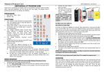
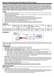
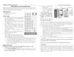
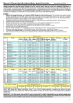
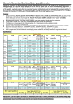
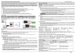
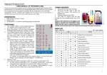
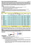
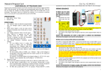
Manual of Sensorless Brushless Speed Controller HW-SM001ENG-20120606 Page 1 of 3 Thanks for purchasing our Electronic Speed Controller (ESC). High power system for RC model can be very dangerous, so we strongly suggest you read this manual carefully. In that we have no control over the correct use, installation, application, or maintenance of our products, no liability shall be assumed nor accepted for any damages, losses or costs resulting from the use of the product. Any claims arising from the operating, failure or malfunctioning etc. will be denied. We assume no liability for personal injury, property damage or consequential damages resulting from our product or our workmanship. As far as is legally permitted, the obligation to compensation is limited to the invoice amount of the affected product. Features: Extreme low output resistance, super current endurance. Multiple protection features: Low voltage cut-off protection / over-heat protection / throttle signal loss protection. 3 start modes: Normal / Soft / Super-Soft, compatible with fixed-wing aircraft and helicopter. Throttle range can be configured to be compatible with all transmitters. Smooth, linear and precise throttle response. Separate voltage regulator IC for microprocessor (except FLYFUN-6A and FLYFUN-10A) with good anti-jamming capability. Maximum speed: 210000 RPM (2 poles motor), 70000 RPM (6 poles motor), 35000 RPM (12 poles motor). The pocket-sized Program Card can be purchased separately for easily programming the ESC at flying field. With a program card, user can activate the music playing function of the ESC, and totally there are 15 rhythms can be selected. Specifications: Fentium Series Class Model 6A 10A 12A 18A 25A 30A FLYFUN-6A FLYFUN-10A FLYFUN-12A FLYFUN-18A FLYFUN-25A FLYFUN-30A FLYFUN-40A 40A FLYFUN-40A-OPTO FLYFUN-60A 60A FLYFUN-60A-OPTO FLYFUN-80A 80A FLYFUN-80A-OPTO FLYFUN-100A 100A FLYFUN-100A-OPTO Cont. Burst BEC BEC Current Current Mode Output (>10s) (Note1 ) 6A 10A 12A 18A 25A 30A 40A 40A 60A 60A 80A 80A 100A 100A 8A 12A 15A 22A 35A 40A 55A 55A 80A 80A 100A 100A 120A 120A Linear 5V/0.8A Linear 5V/1A Linear 5V/2A Linear 5V/2A Linear 5V/2A Linear 5V/2A Switch 5V/3A N/A N/A Switch 5V/3A N/A N/A 5V/3A Switch N/A N/A 5V/3A Switch N/A N/A Battery Cell User Weight Lipo NiMH Programm-able NiCd 2 2-4 2-4 2-4 2-4 2-4 2-6 2-6 2-6 2-6 2-6 2-6 2-6 2-6 5-6 5-12 5-12 5-12 5-12 5-12 5-18 5-18 5-18 5-18 5-18 5-18 5-18 5-18 Available Available Available Available Available Available Available Available Available Available Available Available Available Available Size L*W*H 5.5g 9.5g 10g 21g 24g 26g 39g 35g 63g 60g 72g 69g 76g 32*12*4.5 38*18*6 38*18*7 55*25*6 55*25*9 55*25*9 60*24*15 60*28*12 83*31*16 83*31*14 83*31*16 83*31*14 83*31*16 73g 83*31*14 BEC Output Capability Linear Mode BEC(5V/2A) S witch Mode BEC(5V/3A) 2S Lipo 3S Lipo 4S Lipo 5S Lipo 2S - 4S Lipo 5S-6S Lipo Standard micro servos(Max.) 5 4 3 2 5 4 Note1: BEC means the “Battery Elimination Circuit”. It is a DC-DC voltage regulator to supply the receiver and other equipments from the main battery pack. With the build-in BEC, the receiver needn’t to be supplied with an additional battery pack. IMPORTANT! The ESC named “xxx-xxx-OPTO” hasn’t a built-in BEC, an UBEC (Ultimate-BEC) or an individual battery pack should be used to supply the receiver. And an individual battery pack is needed to power the program card when programming such ESCs, please read the user manual of the Program Card for detail information. Wiring Diagram: Programmable Items: 1. Brake Setting:Enabled / Disabled, default is Disabled 2. Battery Type:Li-xx(Li-ion or Lipo) / Ni-xx(NiMH or NiCd),default is Li-xx. 3. Low Voltage Protection Mode(Cut-Off Mode):Soft Cut-Off (Gradually reduce the output power) or Cut-Off (Immediately stop the output power). Default is Soft Cut-Off. 4. Low Voltage Protection Threshold(Cut-Off Threshold):Low / Medium / High, default is Medium. 1) For lithium batteries, the cells quantity of a battery pack is calculated automatically. Low / medium / high cutoff voltage for each cell is: 2.85V / 3.15V / 3.3V. For example: For a 3 cells lithium pack, when “Medium” cutoff threshold is set, the cut-off voltage of this battery pack will be: 3.15*3=9.45V. 2) For nickel batteries, low / medium / high cutoff voltages are 0%/50%/65% of the startup voltage (it means the initial voltage of a charged battery pack), and 0% means the low voltage cut-off function is disabled. For example: For a 10 cells NiMH battery, fully charged voltage is 1.44*10=14.4V, when “Medium” cut-off threshold is chosen, the cut-off voltage will be: 14.4*50%=7.2V. - Manual of Sensorless Brushless Speed Controller 5. 6. HW-SM001ENG-20120606 Page 2 of 3 Startup Mode:Normal /Soft /Super-Soft ,(300ms / 6s /12s),default is Normal. Normal is preferred for fixed-wing aircraft. Soft or Super-soft are preferred for helicopters. The acceleration of the Soft and Super-Soft modes are slower in comparison, usually taking 6 seconds for Soft startup or 12 seconds for Super-Soft startup from zero throttle advance to full throttle. If the throttle is closed (throttle stick moved to the bottom position, zero throttle) and opened again (throttle stick moved upward) within 3 seconds after the initial startup, the restart-up will be temporarily changed to normal mode to get rid of the chances of a crash caused by slow throttle response. This special design is suitable for aerobatic flight when quick throttle response is needed. Timing:Low / Medium / High,( 3.75°/15°/26.25°),default is Low. Note2 Usually, low timing or medium timing is suitable for most motors. In order to get higher speed and bigger output power, please choose High timing. Note2: After changing the timing setting, please test your RC model on ground before taking off! Begin To Use Your New ESC Note3: In the following instructions, we use the words of “Top position” and “Bottom position” to indicate the location of the throttle stick. Top Position: The throttle value is 100% at this position. Bottom Position: The throttle value is 0% at this position. Please start the ESC in the following sequences: 1. Move throttle stick to the bottom position (zero throttle) and then switch on the transmitter. 2. Connect battery pack to the ESC, the ESC begins the self-test process, a special tone “ 123” emits, means the voltage of the battery pack is in normal range, and then N “beep” tones emits, means the cells quantity of a lithium battery pack. Finally a long “beep------” tone emits, means the self-test is OK, and the aircraft/helicopter is ready to take off. If nothing is happened, please check the battery pack and all the connections; If a special tone “ ” emits after 2 beep tones (“beep-beep-”), means the ESC has entered the program mode, it is because the throttle channel of your transmitter is reversed, please set it correctly; If the very rapid “beep-beep-, beep-beep-” tones emits, means the input voltage is too low or too high, please check your battery’s voltage. 3. “VERY IMPORTANT!” Because different transmitter has different throttle range, please calibrate throttle range before flying. Please read the instruction on page 3------“Throttle Range Setting”. Alert Tone 1. Input voltage is abnormal: The ESC begins to check the voltage when the battery pack is connected, if the voltage is not in the acceptable range, such an alert tone will be emitted: “beep-beep-, beep-beep-,beep-beep-” (Every “beep-beep-” has a time interval of about 1 second. ) 2. Throttle signal is abnormal: When the ESC can’t detect the normal throttle signal, such an alert tone will be emitted: “beep-, beep-, beep-”. (Every “beep-” has a time interval of about 2 seconds) 3. Throttle stick is not in the bottom position: When the throttle stick is not in bottom (lowest) position, a very rapid alert tone will be emitted: “beep-, beep-, beep-”. (Every “beep-” has a time interval of about 0.25 second.) Protection Function 1. Start up failure protection: If the motor fails to start within 2 seconds, then the ESC will cut-off the output power. In this case, the throttle stick MUST be moved to the bottom position (zero throttle) again to restart the motor. (Such a situation happens in the following cases: The connection between ESC and motor is not reliable, the propeller or the motor is blocked, etc.) 2. Over-heat protection: When the temperature of the ESC is over 110 Celsius degrees, the ESC will reduce the output power. 3. Throttle signal loss protection: The ESC will reduce the output power if throttle signal is lost for 1 second, further loss for 2 seconds will cause the output to be cut-off completely. Program Example Setting “Start Mode” to “Super-Soft”, i.e. option #3 of the programmable item #5 1. Enter Program Mode Switch on transmitter, move throttle stick to top position, connect battery pack to ESC, wait for 2 seconds, “beep-beep” tone should be emitted. Then wait for another 5 seconds, special tone “ ” emits, which means program mode is entered. 2. Select Programmable Items Now you’ll hear 8 tones in a loop. When a long “beep------” tone emits, move throttle stick to bottom to enter the “Start Mode” 3. Set Item Value (Programmable Options) “Beep-”, wait for 3 seconds; “Beep-beep-”, wait for another 3 seconds; then you’ll hear “beep-beep-beep”, move throttle stick to the top position, then a special tone “ ” emits, that means you have set the “Start Mode” item to the value of “Super-Soft” 4. Exit Program Mode After the special tone “ ”, move throttle stick to bottom within 2 seconds. Trouble Shooting Trouble Possible Reason After power on, motor does not work, no sound is emitted After power on, motor does not work, such an alert tone emits: “beep-beep-, beep-beep-,beep-beep-” (Every “beep-beep-” has a time interval of about 1 second) After power on, motor does not work, such an alert tone is emits: “beep-, beep-, beep- ”(Every “beep-” has a time interval of about 2 seconds) The connection between battery pack and ESC is not correct Input voltage is abnormal, too high or too low. Check the power connection. Replace the connectors. Check the voltage of battery pack Solution Throttle signal is irregular Check the receiver and transmitter Check the cable of throttle channel - Manual of Sensorless Brushless Speed Controller HW-SM001ENG-20120606 Page 3 of 3 Move the throttle stick to bottom position, and make sure it is Zero throttle at this position. After power on, motor does not work, such an alert tone emits: “beep-, beep-, beep-” (Every “beep-” has a time interval of about 0.25 second) After power on, motor does not work, a special tone “ ” emits after 2 beep tone (beep-beep-) The motor runs in the opposite direction The throttle stick is not in the bottom (lowest) position Direction of the throttle channel is reversed, so the ESC has entered the program mode The connection between ESC and the motor need to be changed. Set the direction of throttle channel correctly The motor stop running while in working state Throttle signal is lost Check the receiver and transmitter Check the cable of throttle channel Land RC model as soon as possible, and then replace the battery pack ESC has entered Low Voltage Cut-off Protection mode Swap any two wire connections between ESC and motor Normal startup procedure: Move throttle stick to bottom and then switch on transmitter. Several “beep-” tones emits, which means the quantity of the lithium battery cells Connect battery pack to ESC, special tone like “ 123” means power supply is OK When the self-test is finished, a long “beep-----” tone emits Move throttle stick upwards to go flying Throttle range setting: (Throttle range should be reset whenever a new transmitter is being used) Switch on t r a n s m i t t e r, move throttle stick to top Connect battery pack to ESC, and wait for about 2 seconds “Beep-Beep-” tone emits, means the throttle range highest point has been correctly confirmed Move throttle stick to the bottom, several “beep-” tones presents the quantity of battery cells A long “Beep-” tone emits, means throttle range lowest point has been correctly confirmed Program the ESC with your transmitter (4 Steps): 2. Select programmable item: 1. Enter program mode 2. Select programmable item 3. Set item’s value (Programmable option) 4. Exit program mode 1. Enter program mode 1) 2) 3) Switch on transmitter, move throttle stick to top , connect the battery pack to ESC Wait for 2 seconds, the motor should emit special tone like “beep-beep-” Wait for another 5 seconds, special tone like “ ” emits, which means program mode is entered After entering program mode, you will hear 8 tones in a loop with the following sequence. If you move the throttle stick to bottom within 3 seconds after one kind of tones, this item will be selected. 1. “beep” brake (1 short beep) 2. “beep-beep-” battery type (2 short beeps) 3. “beep-beep-beep-” cutoff mode (3 short beeps) 4. “beep-beep-beep-beep-” cutoff threshold (4 short beeps) 5. “beep-----” startup mode (1 long beep) 6. “beep-----beep-” timing (1 long 1 short) 7. “beep-----beep-beep-” set all to default (1 long 2 short) 8. “beep-----beep-----” exit (2 long beeps) Note: 1 long “beep-----” = 5 short “beep-” 3. Set item value (Programmable option): 4. Exit program mode You will hear several tones in loop. Set the value matching to a tone by moving throttle stick to the top position when you hear the tone, then a special tone “ ” emits, means the value is set and saved. (Keeping the throttle stick at the top position, you will go back to step 2 and you can select other items; Moving the stick to the bottom position within 2 seconds will exit the program mode directly) There are 2 ways to exit program mode: 1. In step 3, after special “beep-” “beep-beep-” “beep-beep-beep” Items 1 short tone 2 short tones 3 short tones Brake Off On Battery type Li-ion / Lipo NiMH / NiCd Cutoff mode Soft-Cut Cut-Off Low Medium High Normal Soft Super soft Low Medium High Tones Cutoff threshold Start mode Timing tone “ ”, please move the throttle stick to the bottom position within 2 seconds. 2. In step 2, after hearing “beep-----beep-----” tone (that means the item #8), move the throttle stick to the bottom within 3 seconds. -