1
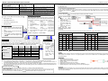
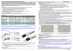
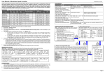
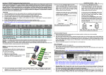
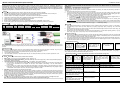
Manual of Sensorless Brushless Speed Controller HW-SM002DUL-20130610 Thanks for purchasing our Electronic Speed Controller (ESC). High power system for RC model can be very dangerous, so we strongly suggest you read this manual carefully. In that we have no control over the correct use, installation, application, or maintenance of our products, no liability shall be assumed nor accepted for any damages, losses or costs resulting from the use of the product. Any claims arising from the operating, failure or malfunctioning etc. will be denied. We assume no liability for personal injury, property damage or consequential damages resulting from our product or our workmanship. As far as is legally permitted, the obligation to compensation is limited to the invoice amount of the affected product. ǏFeaturesǐ 1. Use extreme low resistance PCB to make the whole ESC with super current endurance capability. 2. Military quality capacitors with extreme low resistance increase the ability for preventing unwanted RF noise or interference. 3. Anti-spark circuit eliminates sparks when the battery pack is connecting with the ESC. 4. Protection features: Low-voltage cutoff protection / over-heat protection / throttle signal lost protection. 5. 3 start modes: Normal / Soft / Super-Soft, compatible with fixed-wing aircraft and helicopter. 6. Throttle range can be configured, fully compatible with all transmitters. 7. Smooth and accurate speed control, excellent throttle linearity. 8. Maximum speed: 210000 RPM (2 poles motor), 70000 RPM (6 poles motor), 35000 RPM (12 poles motor). 9. Pocket- sized program card can be purchased separately for extremely easy programming of the ESC at flying field. ǏSpecificationǐ Class Model Cont. Current Burst Current (>10s) BEC Output Battery Cell Lipo 80A FLYFUN-80-HV 80A 100A N/A 5-10 100A FLYFUN-100-HV 100A 120A N/A 5-12 Weight Size NiMH User Programmable 15-30 Yes 125g 88*55*18 15-36 Yes 112g 88*55*18 L*W*H ǏWiring Diagramǐ ǏBegin To Use The New ESCǐ Note: ,Q WKH IROORZLQJ LQVWUXFWLRQV ZH XVH WKH ZRUGV RI ³7RS SRVLWLRQ´ DQG ³%RWWRP SRVLWLRQ´ WR represent the position of the throttle stick. Top Position: The throttle value is 100% at this position. Bottom Position: The throttle value is 0% at this position. Before using your new ESC, please check all the connections to make sure that they are reliable, and then start up the ESC in the following sequence: 1. Move the throttle stick to bottom, and then switch on the transmitter. 2. Connect the receiver battery pack (4-6V) to the receiver, and then connect the main power battery pack to ESC, the ESC begins the self-WHVWSURFHVVDQGWKHPRWRUZLOOHPLWVHYHUDO³EHHS´WRQHVWRrepresent the cells quantity of the lithium battery pack. After 2 seconds a ORQJ³EHHS------´WRQHHPLWs, which means the self-test is OK, and now the RC model is ready to take off. If nothing is happened, please check your battery packs and all the connections; ´HPLWs after 2 beep tones (beep-beep-), means the ESC has entered the program mode, i.e. the throttle ,IDVSHFLDOWRQH³ channel of your transmitter is reversed, please set the direction of throttle channel correctly. ,I D YHU\ UDSLG ³EHHS-beep-, beep-beep-´ WRQH HPLWs 7KH WLPH LQWHUYDO RI HDFK ³EHHS-beep-´ WRQH LV VHFRQG PHDQV WKH LQSXW voltage is too low or too high, please check the battery voltage. 3. VERY IMPORTANT! %HFDXVHGLIIHUHQWWUDQVPLWWHUKDVGLIIHUHQWWKURWWOHUDQJH\RXQHHGWRXVHWKH³7KURWWOH5DQJH6HWWLQJ)XQFWLRQ´WR calibrate the throttle range. Please read the instructions on page 1------³7KURWWOH5DQJH6HWWLQJ´ ǏAlert Toneǐ 1. Input voltage abnormal alert tone: The ESC begins to check the voltage of battery pack when it is power on, if the voltage is not in the acceptable range, such an alert tone emits ³EHHS-beep-, beep-beep-, beep-beep-´ (YHU\ ³EHHS-beep-´ KDV D WLPH LQWHUYDO DERXW second) 2. 7KURWWOHVLJQDODEQRUPDODOHUWWRQH:KHQWKH(6&FDQ¶WGHWHFWWKHQRUPDOWKURWWOHVLJQDOVXFKDQDOHUWWRQHHPLWs³EHHS-, beep-, beep-´ (YHU\³EHHS-´KDVDWLPHLQWHUYDODERXWVHFRQGV 3. Throttle stick is not at its bottom position alert tone: When the throttle stick is not in the bottom (lowest) position, a very rapid alert tone emits³EHHS-, beep-, beep-´(YHU\³EHHS-´KDVDWLPHLQWHUYDODERXWVHFRQG ǏProtection Functionǐ 1. Start up protection: If the motor failed to start up in 2 seconds, the ESC will cut off the output power. In this case, the throttle stick MUST be moved to bottom again and then to restart the motor. (Such a situation happens in the following cases: The connection between ESC and motor is not reliable, propeller is blocked, gearbox is damaged, etc.) 2. Over-heat protection: When the temperature of ESC is higher than a factory-preset value, the ESC will gradually reduce the output power. 3. Throttle signal lost protection: The ESC will reduce the output power if the throttle signal is lost for 1 second, further lost for totally 2 seconds will cause its output to be completely cut off. ǏNormal Startup Procedureǐ Note: There are 2 control wires on the HV controller. The longer one is close to the positive battery wire, which is connected with the receiver, and the shorter one is close to the negative battery wire, which is used to connect the program card to set the programmable parameters of the controller. ǏAnti-Spark Circuitǐ There is a pair of bullet connectors and a thin red wire attached with the positive input wire (red color, thick) of the ESC. They are used to eliminate sparks when the battery pack is connecting with the ESC. Please use it in the following sequence: 1. Disconnect the bullet connectors on the positive input wire (red color, thick) of the ESC. 2. Connect battery wires to the ESC. 3. Connect the bullet connectors on the positive input wire (red color, thick) of the ESC as soon as you hear the special tone ³ƈ´. ǏFeature Explanationǐ 1. Brake˖Brake Enabled / Brake Disabled, default is Brake Disabled 2. Battery Type˖Li-xx(Li-ion or Li-po) / Ni-xx(NiMh or Nicd)ˈdefault is Li-xx. 3. Low Voltage Protection Mode(Cutoff Mode)˖Soft Cutoff (Gradually reduces the output power) or Hard Cutoff (Immediately stops the output power), default is Soft Cutoff. 4. Low Voltage Protection Threshold(Cutoff Threshold)˖Low / Medium / High, default is Medium. For Li-xx batteryˈthe cells quantity of a battery pack is calculated automatically or set manually. Low / Medium / High cutoff voltage for each cell is: 2.6V/2.85V/3.1V. For example: 10 cells Lipo, when ³0edium´ cutoff voltage is set, the cutoff voltage is: 2.85*10=28.5V. For Ni-xx battery, low / medium / high cutoff voltages are 0%/45%/60% of the startup voltage (i.e. the initial voltage of the charged battery pack), 0% means the low voltage protection function is disabled. For example:20 cells NiMH battery, fully charged voltage is 1.44*20=28.89ZKHQ³0HGLXP´YDOXHLVVHWWKHFXWRIIYoltage is: 28.8*45%=12.96VDŽ 5. Start Mode˖Normal /Soft /Super-soft, default is Normal startup. Normal is suitable for fixed-wing aircraft. Soft and Super-soft are suitable for helicopter. The initial speed of Soft and Super-soft mode is very slow so it will take 3 seconds (Soft startup) or 6 seconds (Super-soft startup) from zero speed to full speed. But if the startup process is completed (i.e. The motor is running), then the throttle is closed (that means the throttle stick is moved to bottom position at 0% throttle) and opened again (throttle stick is moved upwards) within 3 seconds, the restart will be temporarily changed to normal mode to get rid of the chances of crash caused by slow throttle response in aerobatic fly. 6. Timing˖Low / Medium / High, default is Low. In normal cases, Low or Medium timing is suitable for most motors. In order to get higher speed, please try the High timing value. Note: After you changing the timing setting, please test your RC model on ground before taking off. Switch on the transmitter, and then move the throttle stick to bottom position Connect the battery pack to ESC, a special tone ³ 123´ will emits, means the power supply is OK Several ³beep-´ tones emit to represent the cells quantity of the lithium battery pack When self-test is finished, a long ³beep ü´ tone emits Ready to go flying now Please note that we use a special way to represent the cells quantity of a lithium battery pack: 1 ORQJ³EHHpü´= 5 short ³beep-´. For example, 2 long ³EHHpü´ plus 2 short ³EHHp-´ (BeepüBeepüBB) means a 12 cells lithium battery pack, 1 long ³EHHpü´ plus 1 short ³EHHp-´ (BeepüB) means a 6 cells lithium battery pack, and so on. ǏThrottle Range Settingǐ Throttle range should be reset when a new transmitter is being used Switch on the transmitter, and move the throttle stick to top position Connect the battery pack to the ESC, and then wait for about 2 seconds ³Beep-beep-´ tone emits, which means the highest point of the throttle range has been correctly confirmed ǏTrouble Shootingǐ Trouble $IWHU SRZHU RQ PRWRU FDQ¶W ZRUN QR sound is emitted $IWHU SRZHU RQ PRWRU FDQ¶W ZRUN VXFK an alert tone emits: ³EHHS-beep-, beep-beep-,beep-beep-´ (YHU\ ³EHHS-beep-´ KDV D WLPH LQWHUYDO about 1 second) $IWHU SRZHU RQ PRWRU FDQ¶W ZRUN VXFK an alert tone emits: ³EHHS-, beep-, beep- ´(YHU\³EHHS-´KDV a time interval about 2 seconds) $IWHUSRZHURQPRWRUFDQ¶WZRUNVXFKD alert tone emits: ³EHHS-, beep-, beep-´(YHU\³EHHS-´KDV a time interval about 0.25 second) Move the throttle stick to the bottom position, and then several ³beep-´ tones emits to represent the number of Lipo battery cells A long ³Beep-´ tone emits, means the lowest point of the throttle range has been correctly confirmed. Possible Reason The connection between battery pack and ESC is not OK Input voltage is abnormal, too high or too low Action Check the power connection. Replace the connector. Check the voltage of battery pack Throttle signal is abnormal Check the receiver and transmitter Check the cable of throttle channel Throttle stick is not in its bottom position (Lowest position). Move the throttle stick to bottom page 1 Manual of Sensorless Brushless Speed Controller $IWHU SRZHU RQ PRWRU FDQ¶W ZRUN D VSHFLDO WRQH ³ ´ HPLWs after 2 beep tones (beep-beep-) The motor runs in opposite direction The motor stop running while in working state HW-SM002DUL-20130610 The direction of throttle channel is reversed, so the ESC has entered the program mode The connection between ESC and the motor need to be changed. Throttle signal is lost ESC has entered Low Voltage Protection mode Some Connections are not reliable Ǐ Program The ESC With Transmitter Stick (4 Steps)ǐ ǐ 1. Enter program mode 2. Select programmable items 3. Set item value (Programmable value) Set the direction of throttle channel correctly Swap any two wire connections between ESC and motor Check the receiver and transmitter Check the cable of throttle channel Land RC model as soon as possible, and then replace the battery pack Check all the connections: battery pack connection, throttle signal cable, motor connections, etc. 2. Select programmable items After entering program mode, you can hear 9 tones in a loop in the following sequence. If you move the throttle stick to bottom within 3 seconds after one kind of tones, then this item will be selected. 1. ³EHHp´ Brake (1 short tone) 2. ³EHHp-beep-´ Battery type (2 short tone) 3. ³EHHp-beep-beep-´ Cutoff mode (3 short tone) 4. ³EHHp-beep-beep-beep-´ Cutoff threshold (4 short tone) 4. Exit program mode 1. Enter program mode 5. ³EHHpü´ Startup mode 1. 6. ³EHHpübeep-´ Timing Lipo battery cells (1 long 2 short) 2. 3. Switch on transmitter, move throttle stick to top position, and then connect the battery pack to ESC Wait for 2 seconds, the motor will emit special WRQHOLNH³EHHp-beep-´ Wait for another 5 seconds, special tone like (1 long tone) (1 long 1 short) 7. ³EHHpübeep-beep-´ 8. ³EHHpübeep-beep-beep-´ Set all to default (1 long 3 short) 9. ³beepübeepü´ (2 long tones) Exit 3. Set item value 4. Exit program mode You will hear tones in loop. Set the value matching to a tone by moving the throttle stick to top when you hear the tone , then a VSHFLDOWRQH³ ´HPLWV which means the value is set and saved. (Keeping the stick at top, you will go back to step 2 and you can select other items; Moving the stick to bottom within 2 seconds, you will exit the programming mode directly) Items Brake beep1 short tone beep-beep- beep-beep-beep beep-beep-beep... 2 short tones 3 short tones N short tones Off On Battery type Li-ion / Li-Po NiMH / NiCd Cutoff mode Soft Cutoff Hard Cutoff Low Medium High Normal Soft Super soft Timing Low Medium High Lipo cells quantity N beep tones represent N cells (N 4 means ³Auto Detect´) Cutoff threshold Startup mode 3. Set Item Value (Programmable Value) ³Beep-´, wait for 3 seconds; ³Beep-beep-´, wait for another 3 seconds; then you¶ll hear ³beep-beep-beep´, move the throttle stick to ´ emits, now you have successfully set the ³Startup Mode´ item to the value of ³Super-soft top position, then a special tone ³ Startup´ 4. Exit Program Mode After the VSHFLDOWRQH³ There are 2 ways to exit program mode. 1. In the step 3, after VSHFLDO WRQH ³ ´ move throttle stick to the bottom within 2 seconds. 2. In step 2, after the ´, move the throttle stick to bottom position within 2 seconds. Ǐ How To Use The Program Cardǐ ǐ 1. Connect the battery (4.8Vto 6V) to the port PDUNHGZLWK³%$77´. 2. Connect the programming lead (shorter control wire) to the port marked with ³%(&´ 3. Connect the main battery pack to the ESC. Please note the above connection sequence cannot be reversed. Now tKH³0XVLF/Lipo cell´LWHPonly means the cells quantity of the lithium battery pack. RHPDUNORQJ³EHHpü´ VKRUW³EHHp-´ ´ emits, which means program mode ³ is entered Tones 2. Select Programmable Items Now you¶ll hear 9 tones in loop. When a long ³beepü´ tone emits, please move the throttle stick to bottom position to enter the ³Startup Mode´ item. LED Lipo Cells D C B A ƻ ƻ ƻ ƻ ƻ ƻ ƻ ƽ ƻ ƻ ƽ ƻ ƻ ƽ ƻ ƽ ƻ ƻ ƽ ƻ ƻ ƽ ƻ ƽ (ƽ = LED is lighting) LED Lipo Cells D C B A Auto detect ƽ ƻ ƻ ƻ 9 CELLS Auto detect ƽ ƻ ƻ ƽ 10 CELLS (37.0V) ƻ Auto detect ƽ ƻ ƽ ƻ 11 CELLS (40.7V) ƽ Auto detect ƽ ƻ ƽ ƽ 12 CELLS (44.4V) ƻ 5 CELLS (18.5V) ƽ ƽ ƻ ƻ Auto detect ƽ 6 CELLS (22.2V) ƽ ƽ ƻ ƽ Auto detect ƽ ƻ 7 CELLS (25.9V) ƽ ƽ ƽ ƻ Auto detect ƽ ƽ 8 CELLS (29.6V) ƽ ƽ ƽ ƽ Auto detect (33.3V) tone ³EHHpübeepü´ ǏAccessory: RPM Sensorǐ ǐ The RPM sensor is an accessory of the high voltage speed controller. (Item #9), move throttle stick to the bottom within 3 seconds. Function It detects the voltage changes at the wires of brushless motor, and then outputs the RPM signal. This RPM sensor can work with some speed control systems for helicopters. And one of its typical applications is to work as the RPM sensor for V-Bar system made by Mikado (www.mikado-heli.de). Note: 1. It very important to set the Lipo battery cells quantity correctly, otherwise the ESC will mistakenly calculate the cut off voltage. 2. In ³Lipo cells TXDQWLW\´ setting process, 1 ORQJ³EHHpü´= 5 short ³beep-´. For example, 2 long ³EHHpü´ plus 2 short ³EHHp-´ means a 12 cells lithium battery pack, 1 long ³EHHpü´ plus 1 short ³EHHp-´ means a 6 cells lithium battery pack. 3. If you are using lithium battery pack, \RX¶GEHWWHUVHWWKH ³Lipo cells TXDQWLW\´ manually. The voltage of a full charged lithium battery pack is different from that of a discharged battery pack, the more cells a battery pack has, the more difficult for the ESC to automatically detect the cells quantity accurately. ǏAn Example about ESC Programmingǐ ǐ In the following example, we set the 6WDUWXS0RGHWR³6XSHU-VRIW´LHvalue #3 of the programmable item #5 1. Enter Program Mode Switch on transmitter, move throttle stick to top, connect battery packs to receiver and ESC, wait for 2 seconds, ³beep-beep´ tone ´ emits, that means the ESC is in the program mode. emits. Then wait another 5 seconds, a special tone ³ Specifications 1. Size: 23mm(L)*10mm(w)*2mm(H) 2. Weight: 6g (Input and output wires are included) 3. Working voltage: 3.5V to 8.4V(1S to 2S Lipo) 4. Current: 1 to 5mA 5. Voltage range of the motor wires: 2 to 14S Lipo 6. RPM range (for 2 poles brushless motor): 1000rpm to 300000rpm 7. Working temperature: 0 to 50 Celsius degree or 32 to 122 Fahrenheit degree How to Use The lead A and lead B is connected to any 2 wires of the brushless motor (Do not need to consider about the polarity). The lead C is a three color wires with a connector at the end, the black wire is the ground wire, the red wire is connected to 3.3V or 5V to supply the sensor, and the white wire outputs RPM signal. page 2