1
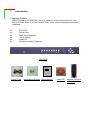
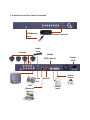
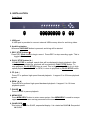
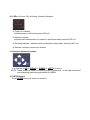
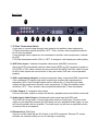
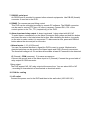
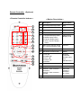
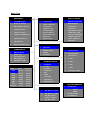
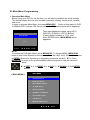
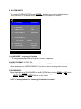
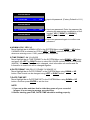
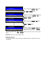
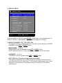
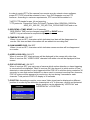
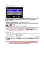
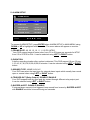
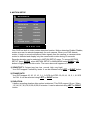
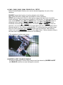
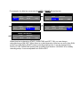
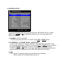
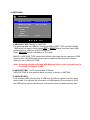
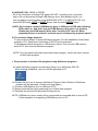
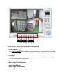
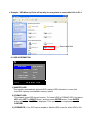
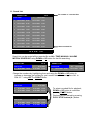
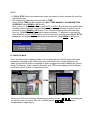
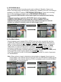
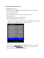
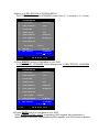
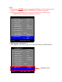
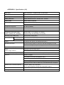
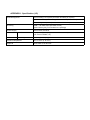
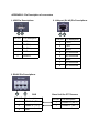
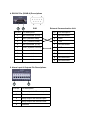
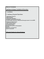
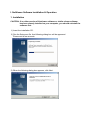
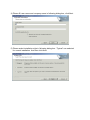
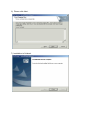
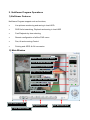
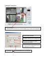
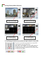
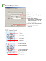
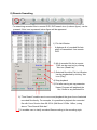
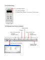
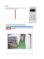
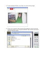
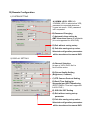
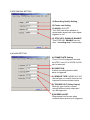
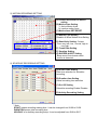
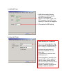
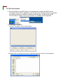
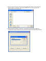
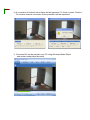
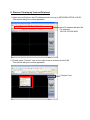
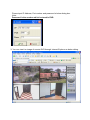
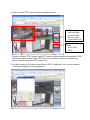
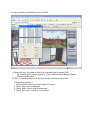
4CH Digital Video Recorder User’s Manual This user’s manual is subject to change without any previous notice by function upgrade or addition. Version_1.2 May, ‘2005 SAFETY PRECAUTIONS CAUTION RISK OF ELECTRIC SHOCK DO NOT OPEN CAUTION: TO REDUCE THE RISK OF ELECTRIC SHOCK, DO NOT REMOVE COVER (OR BACK) NO USER-SERVICEABLE PARTS INSIDE. REFER SERVICING TO QUALIFIED SERVICE PERSONNEL. This label may appear on the rear of the unit due to space limitations. The lightning flash with arrow point symbol, within an equilateral triangle, is intended to alert the user to the presence of uninsulated “dangerous voltage” within the product’s enclosure that may be of sufficient magnitude to constitute a risk of electric shock to persons. The exclamation point within an equilateral triangle is intended to alert the user to the presence of importance operating and maintenance (servicing) instructions in the literature accompanying the appliance. Warning To reduce the risk of fire or electric shock, Do not expose this product to rain or moisture. Do not insert any metallic object through ventilation grills. Power disconnect : Units with or without ON-OFF switches have power supplied to the unit whenever the power cord is inserted into the main source; However, the unit is operational only when the ON-OFF switch is in the ON position. To disconnect it from the main source, you have to disconnect the Power cord. FCC COMPLIANCE STATEMENT A CLASS A computing device subject to certification by the Commission shall be identified pursuant to Par 2.925 et Seq of the chapter. In addition, the label shall include the following statement: This device complies with Part 15 of FCC Rules. Operation is subject to the following two conditions: (1)This device may not cause harmful interference, and (2)This device must accept any interference received, including interference that may cause undesired operation. Where a device is constructed in two or more sections connected by wires and marked together, the statement specified in this Section is required to be affixed only to the main control unit. The users manual or instruction manual for the EUT shall contain the following statement or equivalent. Caution : Changes or Modifications not expressly approved by the party responsible for compliance could void the users authority to operate the equipment. If the EUT requires accessories such as special shield cables and/or connectors to enable compliance with emission limits, the instruction manual for the EUT shall include appropriate instruction on the first page of the text concerned with the installation of the device that these special accessories must be used with the device. It is the responsibility of the user to use the needed special accessories supplied with the equipment. For a CLASS A digital device or peripheral, the instruction furnished the user shall include the following or Similar statement placed in a prominent location in the text of the manual. Note : This equipment has been tested and found to comply with the limits for a CLASS a digital device, pursuant to Part 15 of FCC Rules. These limits are designed to provide reasonable protection against harmful interference when the equipment is operated in a commercial environment, This equipment Generates, uses and can radiate radio frequency energy and, if not in stalled and used in accordance with the instruction manual, may cause harmful interference to radio communications. Operation of the this equipment in a residential area is likely to cause harmful interference in which cause the user will be required to correct the interference at his own expense. Before Starting Your DVR Operation This document is a basic manual for the SIGNALSYNC DVR users. This manual describes the appearance and name of products, how to configure the system program, and how to use the system. Before using SIGNALSYNC DVR, a user should read the contents of user manual, and then deal with the product considering the precautions defined in the manual. To open the system case and touch the inner parts for corrective maintenance, a user should contact the place where he/she purchased the products to get the help from expert. In addition, if there is any question for use or any damage on the product, please contact call the place where he/she purchased the products. Precautions for safety (User should observe) 1. Precautions for installation z Install the product on a flat floor not closed and retain the distance of more than 15 cm from the rear panel to the wall. z Install the product on a well-ventilated place. z Keep it away from strong magnetism or electromagnetic wave. z Installing it near radio equipment such as TV and radio may cause a fault. z Do not install it on a place that is exposed directly to the sun or contains lots of heat such as near a heating apparatus. z Do not install it on a cold place. z Place the equipment or tools in the site remote from a busy road so that people are not hurt. z Do not install it on a place where there is severe vibration, much humidity or soot. z Should use the product in the rated voltage (The equipment is used as both 110V and 220V, but it is set to 220V for delivery. It is possible to adjust it with the changeover switch on the rear panel.) z Connect it to the outlet with the ground terminal. z Discard the vinyl bag well. (It is dangerous to put it on the head.) 2. Precautions for use z For the repair, contact the company or the place where you purchased the product. z Read the user manual before using the product. z Do not open the cover at your discretion because there are parts sensitive to the environment within the equipment. z Arrange the power cord safely and do not touch it with wet hands. z Do not use a loose outlet or a damaged power cable. z Do not use benzene, thinner and alcohol for cleaning. They may deform the product. z Do not touch the exposed terminal. z For the power-off of system, normally turn off the power of the program and then, power off the peripherals. (Do not power it off with the power button on the front panel of body.) z Be careful to prevent a conductive object from falling into a hole that was punched for ventilation. z Do not dissemble and remodel the product. z Do not place a heavy thing on the body. z Do not give a shock during the movement of equipment. z If you use the product in the state of smoke or smell emitted, it may cause a fire or an electric shock. For this case, immediately block the power switch and contact the company or the place where you purchased the product to consult it with a special technician. This user’s manual is subject to change without any notice by function upgrade and so on. Table of Contents I. Introduction 1. Package Contents 2. Features 3. Front Panel and Rear Panel Connection II. Installation 1. Front Panel 2. Rear Panel 3. Remote Controller (Optional) 4. Menu Tree III. Main MENU Programming 1. Overview Main Menu 2. SYSTEM SETUP 3. DISPLAY SETUP 4. RECORDING SETUP 5. ALARM SETUP 6. MOTION SETUP 7. WEEKLY SETUP 8. NETWORK SETUP 9. ARCHIVING 10. HDD INFORMATION 11. SEARCH LIST 12. DISPLAY Mode 13. RECORDING Mode 14. PLAYBACK Mode IV. Software Upgrade Procedure APPENDIX 1. Specification 2. Pin Description of connectors I. Introduction 1. Package Content When purchasing SIGNALSYNC product, unpack it at first and unload it on a flat floor or a place where it is to be located. Then, verify that the following contents are contained. z z z z z z 4CH DVR Power code Rack Mount Bracket User’s manual Install CD Remote controller (Optional) 4CH DVR User’s Manual Power Code Rack Mount Bracket User’s Manual Install CD Remote controller (Optional) 2. Features This DVR provides recording capabilities for four camera inputs. It provides playback or live display and network function while in recording mode. And also it offers the following features: 4 Composite Input Connectors/ 4 Loop-Through Video Connectors - Compatible with Color (NTSC or PAL) and B&W (CCIR and EIA-170) Video Display and Record Video Resolution - NTSC (720x480), PAL (720x576) - Single, QUAD, Sequential Image Display - 4CH multiplexing video recording with 720x480 resolution (NTSC) Compression: M-JPEG - Standard image, high quality; 16KB / field Multiple Search Engines (Date/Time, Event) Records up to 60 NTSC IPS (50 PAL Images per Second) Continuous Recording in Disk Overwrite Mode Simultaneously Record, Playback and Network Archiving using USB Memory Drive - USB 1.1 Storage Class support User-friendly Graphical User Interface (GUI) Manual/ Schedule and alarm/ motion recording Modes (Time and Event) Alarm input Connections, relay output connection Network Function - Dynamic IP (DHCP, Floating IP) support - Live or Recorded Video Access via Ethernet - Remote configuration - DDNS Client support Audio Recording and Playback - 1ch audio support 3. Front Panel and Rear Panel Connection USB Memory Remote Controller Drive Audio Input Cameras RS485 (RTZ Camera) Power Code Audio Alarm Output RS232C Out Monitor LAN (Ethernet) Sensor Input II. INSTALLATION Front Panel 1 2 3 4 5 6 7 8 9 10 11 12 1. USB port A USB port is provided to connect external USB memory drive for archiving video. 2. Archiving button Whenever ARCHIVE button is pressed, archiving will be started. 3. REC/ STOP button Press REC (Red circle) to begin record. Press REC to stop recording again. This is toggle button. 4. PLAY/ STOP button (▶) If PLAY/ STOP is pressed, search lists will be displayed to begin playback. After selecting one recorded file, playback will be started by PLAY/ STOP button. To stop playback, PLAY/ STOP button is used. This is toggle button. While it is in high speed playback mode like FF or REW, it return to playback by PLAY/ STOP button. 5. FF (▶▶) Press FF to perform high speed forward playback. It support 2 to 32 times playback speed. 6. REW (◀◀) Press REW to perform high speed backward playback. It support 2 to 16 times playback speed. 7. PAUSE Press PAUSE to pause playback. 8. MENU/ ESC Press MENU/ESC button to enter menu system. Also MENU/ESC is used to escape upper menu and to save set-up parameter at the same time . 9. QUAD/ SEQ This button is used for QUAD, sequential display. It is rotated as QUADÎ Sequential Î QUAD. 10. LEDs for Power ON, Archiving, Network Indication 1) Power On indicator Indicates power is ON when power LED is lit. 2) Network indicator Indicates data transmission via network is performed when network LED is lit. 3) Archiving indicator: Indicates archiving has been doing when archiving LED is lit. 4) Remote controller sensor input window 11. Direction (Number) buttons It is consists of UP(1), RIGHT(2), DOWN(3), LEFT(4) buttons. NOTE: These buttons is used in numbering input for password , in left/ right movement and increasing/ decreasing parameter for MENU. 12. ENTER button Press ENTER button to confirm a selection. Rear Panel 2 1 3 4 5 6 7 8 9 10 11 1. 75 Ohm Termination Switch If you want to connect loop-through video outputs into another video equipments, 75 Ohm termination switch should be “OFF”. Then, another video equipments should be 75 ohm terminated. If loop through video outputs are not connected to another video equipments, it should be “ON”. If 75 Ohm termination switch “ON” or “OFF” is changed, it will cause poor video quality. 2. 4CH Video Input: 4 channel composite video inputs with BNC connectors Since this DVR automatically detects video format (NTSC or PAL) as soon as power is ON, NTSC or PAL video sources can be connected. But NTSC and PAL video sources for 4CH video inputs can not be mixed. If they are mixed, DVR can’ not be operated properly. 3. 4CH Loop through outputs: 4 channel composite video outputs with BNC connectors If the connection of loop-through video outputs into another video equipments is requested, 4CH Loop-Through outputs can be utilized for it. If loop-through video outputs will be connected to another video equipments, 75 Ohm termination switch should be “OFF”. Then, another video equipments should be 75 ohm terminated. 4. Video Output 1: composite video output Connect this video output to monitor so that live, playback pictures would be monitored. 5. Audio Input, Audio Output: Unbalanced audio signal input with RCA jack This DVR can record audio. Connect the audio source to audio input. Connect audio output to your amplifier because the DVR does not have amplified audio output, so you will need a speaker with an amplifier. The audio input can be from an amplified source or directly from a microphone. 6. Ethernet Port: RJ45 jack Connect a Cat5 cable with an RJ-45 jack to the DVR connector. Remote PC viewer software via network enable you to live viewing or searching. 7. RS232C serial port An RS232 port is provided to connect other external equipments. Use DB-9S (female) connector to connect to the DVR. 8. RS485: For camera pan and tilting control This DVR can be controlled remotely by remote PC software. The RS485 connector can be used to control PTZ (pan, tilt, zoom) cameras. Connect RX+, RX- of the control system to the TX+, TX- (respectively) of the DVR. 9. Alarm input and relay output: 4 alarm inputs and 1 relay output with NO, NC To make secure connections on the Alarm Connector Strip, press and hold the button and insert the wire in the hole below the button. After releasing the button, tug gently on the wire to make certain it is connected. To disconnect a wire, press and hold the button above the wire and pull out the wire. 4 Alarm Inputs: 1,2,3,4,G(Ground) You can use external devices to signal the DVR to react to events. Mechanical or electrical switches can be wired to the Alarm Inputs and GND (Ground) connectors. The threshold voltage is 4.3V and should be stable at least 0.5 seconds to be detected. G (Ground), COM (common): G is same as common. Connect the ground side of the Alarm input to G (Ground). Connect the ground side of relay output to COM connector. Relay output: The DVR support NO, NC relay output at the same time. You can select NO or NC , according to characteristic of mechanical or electrical switch. 10. FAN for cooling 11. AC outlet Connect the power cord to the DVR and then to the wall outlet (100-240V AC). Remote Controller (Optional) < Remote Controller buttons > < Button Description > No 1 2 3 4 Description Button Name 1 Recording Start/ Stop button REC 2 Button LOCK Enable/Disable LOCK 3 Archiving Start button USB 4 Video CH selection buttons 1,2,3,…,0, +10 5 1) Sequential display button 2) QUAD display button 3) 9 picture display button 4) 16/ 8/ 10 picture display button Video Picture Display mode 6 Main picture selection button in 8. 10 picture display mode Function 7 Movement to upper menu ESC 8 Movement to menu mode MENU 9 1) UP (▲) 2) DOWN (▼) 3) LEFT (◀) 4) RIGHT (▶) 5) ENTER Direction (Password Number Input) and ENTER buttons 10 Playback Stop button STOP 11 Playback Start button Search/ PLAY 12 PAUSE/ 1 field movement backward. PAUSE/ 1 field movement forward. Movement forward or backward by 1 Field. 13 Fast Playback buttons FF, REW 5 6 7 8 9 10 11 12 13 Menu Tree MAIN MENU 1 SYSTEM SETUP 1 LANGUAGE 2 DISPLAY SETUP 3 RECORDING SETUP 4 ALARM SETUP 5 MOTION SETUP 6 WEEKLY SCHEDULE 7 NETWORK SETUP 2 3 4 5 6 7 8 9 VIDEO FORMAT PASSWORD ADMIN LOCK TIME FORMAT DATE FORMAT DATE/TIME SET DEFAULT REV STATUS 8 ARCHIVING 9 HDD INFORMATION ALARM SETUP 1 FRAME RATE 2 3 4 5 DURATION SENSOR TYPE TRIGGER OUT BUZZER ALERT START DURATION SUN 00: 00 00: 00 MON TUE WED THU FRI SAT 00: 00 00: 00 00: 00 00: 00 00: 00 00: 00 00: 00 00: 00 00: 00 00: 00 00: 00 00: 00 HOLIDAY NONE NONE 1 ADJUST CHANNEL 2 3 4 5 6 7 BRIGHTNESS CONTRAST PTZ TYPE SEQ DWELL TIME TIME/DATE OSD CAM NUMBER OSD VIDEO LOSS OSD POP-UP DISPLAY POSITION RECORDING SETUP 1 QUALITY 2 3 4 FRAME RATE AUDIO STOP KEY NETWORK SETUP WEEKLY SCHEDULE WEEK DISPLAY SETUP SYSTEM SETUP 1 CONNECT 2 3 4 5 6 7 8 9 IP ADD SUB NET GATE WAY DNS PORT NTP TIME TIME ZONE DDNS STATUS MOTION SETUP 1 SENSITIVITY 2 FRAME RATE 3 DURATION 4 CAM1 5 CAM2 6 CAM3 7 CAM4 8 BUZZER ALERT HDD INFORMATION ARCHIVING 1 ARCHIVING TYPE 2 3 ARCHIVING TIME ARCHIVE INFO NAME: / TOTAL: ARCHIVE LOG 4 1 HARD DISK 2 3 TOTAL FREE FORMAT HDD OVERWRITE III. Main Menu Programming 1. Overview Main Menu Before using your DVR for the first time, you will want to establish the initial settings. This includes items such as time and date, password, display, record mode, network and so on. In order to program Main Menu, first press MENU/ESC button of front panel in DVR. If ADMIN LOCK is set as YES (factory default is YES), below figure will be appeared. PASSWORD LOGIN Then input password number using UP(1), RIGHT(2), DOWN(3), LEFT(4) Buttons (Factory default number is 1111), and press ENTER button. MAIN MENU will be appeared. PASSWORD **** ENTER ▲ ▼ ◀ ▶ EXIT NOTE: To access the DVR Main Menu, press MENU/ESC. To escape MENU, MENU/ESC button is also used. Buttons for movement in Menu are ◀(4), ▶(2). Button for selection is ENTER, Buttons for increasing or decreasing parameter are ▲(1), ▼(3). Press MENU/ESC to return to the previous MENU after setting and to save the values of setup. Í ◀(LEFT & 4), ▶(RIGHT & 2), ▲(UP & 1), ▼(DOWN & 3) and ENTER buttons. MAIN MENU < MAIN MENU > 1 SYSTEM SETUP 2 DISPLAY SETUP 3 RECORDING SETUP 4 ALARM SETUP 5 MOTION SETUP 6 WEEKLY SCHEDULE 7 NETWORK SETUP 8 ARCHIVING 9 HDD INFORMATION ENTER ▲ ▼ ◀ ▶ EXIT 2. SYSTEM SETUP To access SYSTEM SETUP, press ENTER button after moving highlight bar to SYSTEM SETUP in MAIN MENU. Below menu will appear on monitor. 1 SYSTEM SETUP 1 LANGUAGE : ENG/CHN 2 VIDEO FORMAT : NTSC 3 PASSWORD : **** 4 ADMIN LOCK : YES 5 TIME FORMAT : 24HOURS 6 DATE FORMAT : MM-DD-YY 7 DATE/TIME SET : 05: 20: 2005 10:50:11 8 DEFAULT : YES / NO 9 REV STATUS : VERSION 1:1:2 ENTER ▲ ▼ ◀ ▶ EXIT 1) LANGUAGE : Language Selection The languages supported are English, Chinese, Japanese. 2) VIDEO FORMAT: NTSC/ PAL Video format is automatically detected after power ON. The detected video information will be displayed on VIDEO FORMAT. User don’t need to change video format. 3) PASSWORD: Move Highlight bar to PASSWORD in the SYSTEM Menu using DOWN or UP button . And then press ENTER to change password. For four digit password input, UP, RIGHT, DOWN and LEFT buttons can be used. NOTE: Factory Default is “Pressing UP button four times”. SYSTEM SETUP 2 PASSWORD **** OLD Input old password. (Factory Default is 1111) **** NEW Input new password. Enter the password by pressing the appropriate combination of four number, UP(1), RIGHT(2), DOWN(3), LEFT(4) buttons. **** AGN Input new password again to confirm new password. SYSTEM SETUP 2 PASSWORD SYSTEM SETUP 2 PASSWORD 4) ADMIN LOCK: YES/ NO Move Highlight bar to ADMIN LOCK in the SYSTEM Menu using DOWN or UP button . If ADMIN LOCK is selected as YES by LEFT or RIGHT, password is requested whenever entering menu. If NO, password isn’t requested. 5) TIME FORMAT: 24/ 12 HOURS Move Highlight bar to TIME FORMAT in the SYSTEM Menu using DOWN or UP button and press the LEFT or RIGHT button to select 24 HOURS (military time) or 12 HOURS (AM/PM). Whenever Time Format is changed, clock information on monitor and file information in search list will be changed together. 6) DATE FORMAT: MM-DD-YY/ DD-MM-YY/ MM-DD-YY Move Highlight bar to DATE FORMAT in the SYSTEM Menu using DOWN or UP button. Date format can be changed using LEFT or RIGHT button. 7) DATE/ TIME SET: Move Highlight bar to DATE/TIME SET in the SYSTEM Menu using DOWN or UP button. And then press ENTER to set the time. NOTE: 1. If you set a date and time that is older than some of your recorded images, it is not easy to manage recorded files. 2. Before starting your DVR, DATE/ TIME should be setting properly. SYSTEM SETUP 6 DATE/TIME SET Year is changed by DOWN or UP button. 2004:01:11 10:50:11 By LEFT or RIGHT button. SYSTEM SETUP 6 DATE/TIME SET 2004:01:11 10:50:11 Month is changed by DOWN or UP button. LEFT or RIGHT button. SYSTEM SETUP 6 DATE/TIME SET 2004:01:11 10:50:11 Date is changed by DOWN or UP button. … LEFT or RIGHT button. SYSTEM SETUP 6 DATE/TIME SET 2004:01:11 10:50:11 Time is changed by DOWN or UP button. To confirm DATE/TIME setting, ENTER button should be pressed. After setting DATE/ TIME, ESC or ENTER button can be used in order to return upper Menu. 8) DEFAULT: Return to factory default mode. 9)REVISION STATUS It shows DVR software version. Whenever upgrading software, upgraded version will be displayed. 3. DISPLAY SETUP 2 DISPLAY SETUP 1 ADJUST CHANNEL CH1, CH2, CH3, CH4 BRIGHTNESS 1-99 % CONTRAST 1-99 % PTZ TYPE 2 SEQ DWELL TIME NONE, 1-60 SEC 3 TIME/ DATE OSD ON/ OFF 4 CAM NUMBER OSD ON/ OFF 5 VIDEO LOSS OSD ON/ OFF 6 POP-UP DISPLAY ON/ OFF 7 POSITION ENTER ▲ ▼ ◀ ▶ EXIT To access DISPLAY SETUP, press ENTER button after moving highlight bar to DISPLAY SETUP in MAIN MENU. Above menu will appear on monitor. 1) ADJUST CHANNEL: CH1, CH2, CH3, CH4 The camera channel to adjust brightness, contrast can be selected by ADJUST CHANNEL using LEFT or RIGHT button. BRIGHTNESS: 1 to 99 % BRIGHTNESS can be changed using LEFT or RIGHT button. - NOTE: Minimum value is 1 (very dark), maximum value is 99 (very bright). CONTRAST: 1 to 99 % CONTRAST can be changed using LEFT or RIGHT button. PTZ TYPE (Pan, Tilt and zooming protocol selection) The high end camera(s) with panning, tilting and zooming function would be connected with some of video inputs. The camera(s) has(have) its own control protocol to control panning, tilting and zooming, according to PTZ camera manufacturer. In order to control PTZ of the camera from remote area by network viewer software, proper PTZ TYPE should be selected in here. Your DVR supports over ten PTZ cameras. According to customer requirements, PTZ control will be added in it. * NOTE: PTZ stands for pan, tilt and zooming. * PTZ protocols: Panasonic/ Pelco-D/ PelcoP/ Techwin/ Niko/ DRX502A_DSC230s /KRE_301_302/ GC_755_NP/ TOA_CC554/ RAS716LS and so on. 2) SEQ DEWLL TIME: NONE/ 1 to 60 seconds. SEQ DWELL TIME can be changed using LEFT or RIGHT button. - NOTE: It is just reflected in sequential display mode. 3) TIME/DATE OSD: ON/ OFF When it is set as OFF, characters which indicates time/ date will be disappeared on monitor. But time and date information still are added into recording files. 4) CAM NUMBER OSD: ON/ OFF When it is set as OFF, characters which indicates camera number will be disappeared on monitor. 5) VIDEO LOSS OSD: ON/ OFF When it is set as OFF, black pictures will be displayed in the cameo with video loss. When it is set as ON, “VIDEO LOSS” character with white color will be displayed in blue screen. 6) POP-UP DISPLAY: ON/ OFF When it is set as OFF, pop-up image of camera which motion detection or alarm triggering is occurred will not displayed. When it is set as ON, the channel (s) which motion is (are) detected or external alarm is (are) triggered will be POP-UP in monitor during maximum 30 seconds. In case that motion detection or alarm event is occurred more than two channels, POP-UP picture will be appeared in monitor turn by turn during 3 seconds for each channels. Total period of POP-UP display is 30 seconds. 7) POSITION: According to monitor, even same Video signal can be displayed on different position of monitor by the deflection characteristic of it. In this case, vertical and horizontal display position can be adjusted by “VERTICAL” and POSITION “HORIZONTAL” of POSITION. 1 VERTICAL : 52 2 HORIZONTAL : 205 3 DEFAULT : NO 4. RECORDING SETUP 3 RECORDING SETUP 1 QUALITY : HIGH 2 FRAME RATE : 60/ IPS 3 AUDIO : OFF 4 STOP KEY : DISABLE ENTER ▲ ▼ ◀ ▶ EXIT To access RECORDING SETUP, press ENTER when RECORDING SETUP in MAIN MENU using DOWN or UP is highlighted with blue color. The menu above will appear on monitor. 1) QUALITY: LOW, STANDARD, STANDARD PLUS, HIGH Your DVR support four recording quality from low to high. It can be selected using LEFT or RIGHT button. 2) FRAME RATE: 60, 30, 15, 10, 5, 1, 0.5 IPS.(NTSC) Your DVR support several frame rates from 0.5 to 60 Image per seconds for NTSC from 0.5 to 50 IPS for PAL. It can be selected using LEFT or RIGHT button. NOTE: when your DVR is in recording mode, some of parameters related to RECORDING can’t be changed. 3) AUDIO: ON/ OFF Your DVR can select whether to record audio signal with video signal together or not. It can be selected using LEFT or RIGHT button. 4) STOP KEY: DISABLE/ ENABLE In case of manual recording, manual recording is started and stop by the REC/ STOP button . This STOP KEY ENABLE can protect the “recording stop” which is not intended. NOTE: While your DVR is on recording mode, it doesn’t support the setup related to the recording including recording quality, frame rate, audio ON/ OFF and date/ time setup in SYSTEM SETUP. 5. ALARM SETUP 4 ALARM SETUP 1 FRAME RATE : 60/ IPS 2 DURATION : 3 MIN 3 SENSOR TYPE : NONE/ N.O/ N.C 4 TRIGGER OUT : DISABLE 5 BUZZER ALERT : DISABLE ENTER ▲ ▼ ◀ ▶ EXIT To access ALARM SETUP, press ENTER when ALARM SETUP in MAIN MENU using DOWN or UP is highlighted with blue color. The menu above will appear on monitor. 1) FRAME RATE: 60, 30, 15, 10, 5, 1, 0.5 IPS.(NTSC) Your DVR support several frame rates from 0.5 to 60 Image per seconds for NTSC from 0.5 to 50 IPS for PAL. It can be selected using LEFT or RIGHT button. 2) DURATION: It define recording duration after motion is detected. This DVR support 10 sec, 30 sec, 1,2,3,4,5,6,7,8,9,10,20,30,40,50,60 minutes. It can be selected using LEFT or RIGHT button. 3) SENSOR TYPE: NONE/ N.O/ N.C Your DVR can select the input type for external alarm inputs which usually has normal open or normal close using LEFT or RIGHT button. 4) TRIGGER OUT (Relay Output): DISABLE/ ENABLE Your DVR support both dry open and dry contact through different relay output port. It can be selected using LEFT or RIGHT button. 5) BUZZER ALERT: DISABLE/ ENABLE If external alarm sensor(s) be triggered, beep sound from buzzer by BUZZER ALERT with ENABLE would be occurred during two seconds. 6. MOTION SETUP 5 MOTION SETUP 1 SENSITIVITY : normal 2 FRAME RATE : 60/ IPS 3 DURATION : 1 MIN 4 CAM1 : DISABLE 5 CAM2 : DISABLE 6 CAM3 : DISABLE 7 CAM4 : DISABLE 8 BUZZER ALERT : DISABLE ENTER ▲ ▼ ◀ ▶ EXIT Your DVR has built-in video motion detection function. Motion detection Enable/ Disable, motion area can be selected separately for each camera. When your DVR detects motion, it begin to record multiplexed video signals from the camera or cameras which motion is detected and display only the camera with motion during 30 seconds. Recoding duration can be selected in MOTION SETUP menu. To access MOTION SETUP, press ENTER when MOTION SETUP in MAIN MENU using DOWN or UP button is highlighted with blue color. The menu above will appear on monitor. 1) SENSITIVITY: 5 steps (very low, low , normal, high, very high) Your DVR support 5 sensitivity levels. It can be selected using LEFT or RIGHT button. 2) FRAME RATE: Your DVR support 60, 30, 15, 10, 5, 1, 0.5 IPS for NTSC. 50, 25,16, 10, 5, 1, 0.5 IPS for PAL. It can be selected using LEFT or RIGHT button. 3) DURATION: It define recording duration after motion is detected. This DVR support 10 sec, 30sec, 1,2,3,4,5,6,7,8,9,10,20,30,40,50,60 minutes. It can be selected using LEFT or RIGHT button. 4) CAM1, CAM2, CAM3, CAM4: DISABLE/ ALL/ SETUP Motion Enable/Disable, Motion zone can be selected separately for each of four cameras. DISABLE means that function of motion detection isn’t utilized. ALL means that entire image area is selected for motion detection. SETUP can be selected in order to select given image area which want to monitor motion detection. Total motion area consists of 14x10 blocks. To select arbitrary motion zone, select SETUP using LEFT or RIGHT button. And then press ENTER button to designate motion areas in 14x10 blocks. You can use LEFT or RIGHT button for horizontal movement UP or DOWN button for vertical movement, ENTER button for selection. You can define the area of the image where you don’t want to detect motion. Selected blocks in 14x10 blocks will be blinking. To remove previously defined image block for motion detection, press ENTER button again at that block. After defining motion zone, press MENU/ESC button to return upper Menu. Motion detection zone is the area which edge of the motion blocks is not flickering. < The example of motion area setup > 5) BUZZER ALERT: DISABLE/ ENABLE If motion be detected in motion area, beep sound from buzzer by BUZZER ALERT with ENABLE would be occurred during two seconds. 7. WEEKLY SCHEDULE 6 WEEKLY SCHEDULE WEEK START DURATION SUN 00: 00 00: 00 OFF MON 00: 00 00: 00 OFF TUE 00: 00 00: 00 OFF WED 00: 00 00: 00 OFF THU 00: 00 00: 00 OFF FRI 00: 00 00: 00 OFF SAT 00: 00 00: 00 OFF HOLIDAY NONE NONE OFF ▲ ▼ ◀ ▶ EXIT ENTER To setup WEEKLY SCHEDULE, press ENTER when WEEKLY SCHEDULE in MAIN MENU using DOWN or UP button is highlighted with blue color. The menu above will appear on monitor. WEEKLY SCHEDULE WEEK START DURATION SUN 00: 00 00: 00 OFF MON 00: 00 00: 00 OFF WEEK NONE NONE OFF ENTER ▲ ▼ ◀ ▶ EXIT When blue bar is on SUN, blue bar movement from SUN to SAT and HOLIDAY can be selected by DOWN or UP button. To return Main Menu, MENU/ESC button is used. To move START, DURATION and OFF/ ON, LEFT or RIGHT Button is used. To decide the time for START time, DURATION and OFF/ ON, time with bold character or OFF/ ON at that position can be changed by DOWN or UP button . For example, the blue bar movement by LEFT or RIGHT Button like this; WEEKLY SCHEDULE START SUN 00: 00 WEEKLY SCHEDULE DURATION 00: 00 START OFF SUN WEEKLY SCHEDULE START SUN 00: 00 00: 00 OFF WEEKLY SCHEDULE DURATION 00: 00 00: 00 DURATION START OFF SUN 00: 00 DURATION 00: 00 OFF WEEKLY SCHEDULE START SUN 00: 00 DURATION 00: 00 OFF When blue bar is placed on START, DURATION and OFF/ ON, you can change value like time or ON/ OFF. When there is no bold character, blue bar can move from SUN to SAT and HOLIDAY. START means recording starting time. It can be changed from 00:00 to 23:59. DURATION means total recording time duration. HOLIDAY is for holiday recording setup. It can be adjusted from SUN to SAT. 8. NETWORK SETUP 7 NETWORK SETUP 1 CONNECT : STATIC/ DHCP 2 3 4 5 6 7 8 9 IP ADD SUB NET GATE WAY DNS PORT NTP TIME TIME ZONE DDNS STATUS : 192. 168. 123. 171 : 255. 255. 255. 000 : 192. 168. 123. 254 : 168.126.063.001 : 5000 : OFF : GMT + 09:00 : NONE/OK/ERR ENTER ▲ ▼ ◀ ▶ EXIT To access NETWORK SETUP, press ENTER when NETWORK SETUP in MAIN MENU using DOWN or UP is highlighted with blue color. The menu above will appear on monitor. 1) CONNECT: STATIC or DHCP You DVR can select STATIC IP or DHCP using LEFT or RIGHT Button. 2) IP ADDRESS, 3) SUB NET MASK, 4) GATE WAY: If static IP be selected, IP address, SUB NET, and GATEWAY should be written on it manually, according to network environment. LEFT or RIGHT button is used for movement, DOWN or UP button is used for changing the value of parameter. If DHCP be selected, your DVR would read network parameters automatically from network equipment, display them on IP ADD, SUB NET and GATEWAY. 5) DNS: DNS : Server IP setting to change Domain Name into IP address. Default value is KT’s Domain Name Server IP. 6) PORT : Port number for TCP/IP connection in DVR Net-Viewer should have same port Number to access remote DVR through network. (Ex. 80 TCP www-http World Wide Web HTTP ) (Ex 123 UDP NTP Network Time Protocol ) Default Port No. is 5000. If Port is set as 5000, port number of from 5000 to 5002 is used in DVR. Therefore, If DVR is used in network environment with firewall, port number of from 5000 to 5002 should be opened for DVR’s external access. If IP sharing machine is used with DVR, “port forwarding” should be done. 7) NTP TIME: OFF/ON DVR can synchronize “standard time” with Time Server using Network Time Protocol. NOTE: If DNS server is not set properly in fixed IP address, this function will not be operated. 8) TIME ZONE SETTING Time information can be synchronized with time server. For example to synchronize time, GMT + 8 for Taiwan, GMT + 9 for Korea or Japan. 9) DDNS STATUS: Dynamic DNS status display (This DDNS status is just readable.) It is recommended not to use this DDNS service for fixed IP or IP sharing machine. NONE – It indicate that DDNS is not used. ERR - DDNS IP update failure OK - Normal operation < How to use DDNS service > 1. Create User ID, password and domain Name in the company which support DDNS service with free of charge. (Ex. www.dyndns.org ) 2. Access to your DVR using any PC installed Net-Viewer. 3. Input User ID, password, site and “DDNS enable” received from company which support DDNS service in DDNS setting of remote setup of Net-Viewer. DVR will be upgraded as soon as DDNS setting by remote setup of Net-Viewer is finished. 4. Check the status of 8. DDNS STATUS of NETWORK SETUP. 9. ARCHIVING 8 ARCHIVING 1 ARCHIVING TYPE : SINGLE/ MOTION 2 ARCHIVING TIME : 1 SEC to 30 MIN 3 ARCHIVE INFO NAME: TOTAL: FREE: 4 ARCHIVE LOG ENTER : NONE ▲ ▼ ◀ ▶ EXIT 1) ARCHIVE TYPE: SINGLE or MOTION For archiving data via USB port, first set-up ARCHIVING TYPE and ARCHIVING TIME which you want to have using LEFT or RIGHT Button. And then insert USB memory drive in USB port of DVR front panel. Press ARCHIVE button in playback or live mode. SINGLE in ARCHIVE TYPE means that field by field image can be captured in USB memory drive. MOTION means that it can be captured during the time duration when you set in ARCHIVE TIME. Note: Archiving operation through USB Memory Drive can be executed only in live mode or playback mode. 2) ARCHIVE TIME: 1 to 60 seconds and 30 Minute. ARCHIVE TIME is time duration which you want to archive in MOTION. 3) ARCHIVE INFO: First, connect USB memory drive in USB port of DVR front panel. And then enter menu mode. You can see the information of USB Memory Drive inserted in DVR like USB memory drive manufacturer, total memory size, available memory size. 4) ARCHIVE LOG: NONE or ENTER All of log information including DVR power ON/ OFF, recording time, event time and so on can be backup through USB Memory drive. After backup log file, you can see backup log information using WORD-PAD of PC. For ARCHIVE LOG, first select ENTER using LEFT or RIGHT Button. And the press ENTER button. NOTE: Don’t keep to connect USB Memory drive in USB port of DVR after finishing DVR power up. And don’t plug out USB Memory drive when it is working. Please plug out USB memory drive after “Archive LED” turn off. When playback pictures is archived, archived speed is followed by playback speed. 5) The archived image playback To play archived image, it needs NetViewer program. For the installation of NetViewer program in PC, Setup.exe in NetViewer S/W CD can be executed. To playback archived image file in USB memory driver, First connect USB memory drive to PC, then execute Netviewer program. NOTE: For more detail information about NetViewer program, confer the user’s manual of NetViewer program. < The procedure of archived file playback using NetViewer program > A) Install NetViewer program as executing Setup.exe in NetViewer S/W CD. After finishing installation, next icon will be appeared in PC. B) Double-click the icon to execute NetViewer Program. Main Window of NetViewer program will be appeared. (Confer next page figure.) C) Connect USB Memory drive to USB port of PC. D) Search archived files using searching icon of NetViewer program. E) Playback the archived file as double-clicking the file. NOTE: USB Memory driver usually will be recognized as removable disk in most of PC. Confer example of recognizing USB Memory drive in PC. 1 2 3 4 5 6 7 8 < NetViewer Program > NOTE: On the viewer program buttons in Viewer GUI 1. Search Button: This Search Button can be used to find archived image in USB Memory drive. After searching the image files, double-click the file. And then it will be playbacked. 2. Slide bar; In order to move much faster the archived image where you want to see, just drag this slice bar forward or backward. 3. Move to beginning of archived images 4. Move single frame backward 5. Playback button 6. Stop/ PAUSE button 7. Move single frame forward 8. Move to end of archived images < Example; USB Memory Drive will usually be recognized as removable Disk in PC > Removable Disk 10. HDD INFORMATION 9 HDD INFORMATION 1 HARD DISK : WDC WD1200 TOTAL : 111GB FREE : 111GB 2 FORMAT HDD : NO 3 OVERWRITE : OFF ENTER ▲ ▼ ◀ ▶ EXIT 1) MASTER HDD: This machine automatically detects HDD, display HDD information in menu like total HDD capacity and available memory space. 2) FORMAT HDD: This support quick HDD format function. To format HDD in FORMAT HDD, first select YES using LEFT or RIGHT Button, and then press ENTER button. Press ENTER button again after MASTER is displayed. Then quick format is implemented with CONFIRM. 3) OVERWRITE: Your DVR can be enable or disable HDD overwrite, when HDD is full. 11. Search List SEARCH LIST LIST TYPE ALL 1 10-15-2004 10:20 10-15-2004 11:20 2 10-15-2004 12:20 10-15-2004 13:20 3 10-15-2004 13:20 10-15-2004 4 10-15-2004 14:20 10-15-2004 15:20 5 10-15-2004 16:20 10-15-2004 17:20 6 10-15-2004 18:20 10-15-2004 18:50 7 10-15-2004 19:20 10-15-2004 19:25 8 10-15-2004 20:20 10-15-2004 20:25 9 10-15-2004 21:20 10-15-2004 21:50 10 10-15-2004 22:00 10-15-2004 23:10 ENTER The number of recorded files 10/ 10 10-15-2004 14:20 Latest recorded file ▲ ▼ ◀ ▶ EXIT Search list can be sorted all the recorded file as ALL/ TIME/ MANUAL/ ALARM/ MOTION/ SCHEDULE using DOWN or UP button for fast file searching. SEARCH LIST 10/ 10 LIST TYPE ALL 1 10-15-2004 11:20 10-15-2004 10:20 10-15-2004 SEARCH LIST 10/ 10 LIST TYPE ALL 1 10-15-2004 11:20 10-15-2004 10:20 10-15-2004 Change the numbers by highlighting them and using the DOWN or UP button to increase or decrease the number for year/ month/ date after moving from ALL to 2004-10-** using LEFT or RIGHT Button. SEARCH LIST 10/ 10 LIST TYPE ALL 1 10-15-2004 10:20 10-15-2004 11:20 10 10-15-2004 22:00 10-15-2004 23:10 SEARCH LIST 10-15-2004 10/ 10 LIST TYPE ALL 1 10-15-2004 10:20 10-15-2004 11:20 10 10-15-2004 22:00 10-15-2004 23:10 10-15-2004 To select recorded file for playback, DOWN or UP button is used after pressing ENTER button. . Playback will be started by pressing PLAY/ STOP button (▶) button. NOTE: 1. If PLAY/ STOP button be pressed two times successively, latest recorded file could be playbacked soon. 2. The example for searching recorded files by TIME. Search list by TIME can be selected from ALL/ TIME/ MANUAL/ ALARM/ MOTION/ SCHEDULE using DOWN or UP button. After moving 11-20-2004 date area using LEFT or RIGHT Button (and then related date character would be turned into bold character), the date which want to search can be selected by using DOWN or UP button. Then recorded files just after selected date, time (ex, 11-20-2004 10:33) would be listed as bellows. To playback a recorded file from listed files, press ENTER button to move listed files. And then press PLAY/ STOP button (▶) for playback after selecting the recorded file using DOWN or UP button. SEARCH LIST LIST TYPE 2/ 2 TIME 11-20-2004 10:33 1 11-20-2004 10:33 11-20-2004 11:20 2 11-20-2004 22:00 11-20-2004 23:10 12. DISPLAY Mode There are three kind of display modes such as single (as full), QUAD, sequential mode regardless recording mode. When there are motion detection or alarm triggering, the video channel which motion is detected or alarm is triggered would be display on monitor during 30 Seconds. After it pass 30 Seconds, your DVR would display previous display mode such as full, QUAD or sequential picture. ▶ 12: 03: 2004 06: 26: 23 PM MAIN MENU 1 SYSTEM SETUP 2 DISPLAY SETUP 3 RECORDING SETUP 4 ALARM SETUP 5 MOTION SETUP 6 WEEKLY SCHEDULE 7 NETWORK SETUP 8 ARCHIVING 9 HDD INFORMATION When your DVR is in recording, playback and network mode, on left top corner of monitor. But it is on MENU Mode, ▶ disappeared as upper figure. are displayed ▶ are temporarily 13. RECORDING Mode There are several kinds of recording modes such as Manual, Schedule, Alarm event, Motion. Recording quality including high, standard plus, standard, low for all of recording is decided by the QUALITY setting in RECORDING SETUP Menu. Frame rate, recording time can be separately selected in each of RECORDING SETUP Menu. It is recorded on HDD that 4Ch video input signals are multiplexed with field by field. 1) Manual recording is started by REC/STOP button of front panel. 2) WEEKLY RECORDING can be started by setting in WEEKLY SETUP. 3) Motion Recording can be started when any motions in image are detected. 4) Alarm recording is started by external alarm trigger input. 12: 03: 2004 06: 26: 23 PM Recording Mode 12: 03: 2004 06: 26: 23 PM 14. PLAYBACK Mode Normal playback can be started PLAY/ STOP button (▶) after recorded file selection in search list. While your DVR is in playback mode, the camera channel which want to watch could be selected by UP(1), RIGHT(2), DOWN(3), LEFT(4) button. Fast forward (FF, ▶) or fast backward playback (REW ◀◀) can be done by FF (▶▶) and REW (◀◀) button. In order to freeze picture in playback, PAUSE button is used. The button. movement of single field in still picture mode can be fulfilled by PAUSE For selecting the forward or backward playback of single field, FF (▶▶) and REW (◀◀) button would be needed to press before using PAUSE button. Your DVR supports x2,x4,x8,x16,x32 playback for Fast Forward, x2,x4,x8,x16 play back for Fast Backward. Note: When motion in image is detected or external alarm is triggered, there is pop-up image display of the channel during 30 seconds. But your DVR doesn’t display pop-up image display of the channel when your DVR is in playback mode or search list Menu to minimize user’s inconvenience. 12: 03: 2004 06: 26: 23 PM Playback Mode ▶ 12: 03: 2004 06: 26: 23 PM 15. PTZ Control Procedure a) Select the camera (which PTZ camera is connected) to control PTZ using UP(1), RIGHT(2), DOWN(3), LEFT(4) buttons of front panel in your DVR. b) Press ENTER button to select PTZ mode. PTZ MODE OSD will be displayed on upper right corner of monitor. c) Use UP(1), DOWN(3) button for up and down movement of PTZ camera, LEFT(4), RIGHT(2) for left and right movement and FF (▶▶), REW (◀◀) buttons for zoom IN and OUT. d) To escape PTZ control mode, press ENTER button or any button. Then the PTZ MODE OSD on upper right corner of monitor will be disappeared. NOTE: Before using PTZ control mode, please check that right selection of PTZ protocol in PTZ TYPE of DISPLAY SETUP is done. IV. Software Upgrade Procedure 1. S/W Upgrade procedure 1) Copy files including - trd400_tar into USB Memory Drive using PC in advance. 2) Turn off power of your DVR. 3) Turn on power of your DVR. 4) Insert USB Memory Drive into USB port in front panel of DVR. 5) Press MENU button. 6) Input password and then press ENTER button. 7) Select SYSTEM SETUP menu in main menu. * It takes several seconds for your DVR to display SYSTEM SETUP menu because upgrade files like - trd400_tar has been read into your DVR. SYSTEM SETUP 1 LANGUAGE : ENG/CHN 2 VIDEO FORMAT : NTSC 3 PASSWORD : **** 4 ADMIN LOCK : YES 5 TIME FORMAT : 24HOURS 6 DATE FORMAT : MM-DD-YY 7 DATE/TIME SET : 05: 20: 2005 8 DEFAULT 9 REV STATUS ENTER 10:50:11 : YES / NO : VERSION 1:1:1 ▲ ▼ ◀ ▶ EXIT * NOTE: The terminology of 9. REV STATUS of SYSTEM SETUP in version 1.1.1 (current version) is changed into 9. REV STATUS in version 1.1.2 (new version). After finishing S/W upgrade, terminology will be changed. 8) Move to 9. REV STATUS of SYSTEM SETUP. The SYSTEM MENU shows UPGRADE version from 1.1.1 (current) to 1.1.2 (new). SYSTEM SETUP 1 LANGUAGE : ENG/CHN 2 VIDEO FORMAT : NTSC 3 PASSWORD : **** 4 ADMIN LOCK : YES 5 TIME FORMAT : 24HOURS 6 DATE FORMAT : MM-DD-YY 7 DATE/TIME SET : 05: 20: 2005 8 DEFAULT 9 REV STATUS 10:50:11 : YES / NO : UPGRADE 1:1:1 Î 1:1:2 ▲ ▼ ◀ ▶ EXIT ENTER 9) Press RIGHT(2) button of front panel in your DVR. “9. REV STATUS : UPGRADE” will be changed into “9. REV STATUS : CONFIRM” SYSTEM SETUP 1 LANGUAGE : ENG/CHN 2 VIDEO FORMAT : NTSC 3 PASSWORD : **** 4 ADMIN LOCK : YES 5 TIME FORMAT : 24HOURS 6 DATE FORMAT : MM-DD-YY 7 DATE/TIME SET : 05: 20: 2005 8 GMT HOUR SET 9 REV STATUS ENTER 10:50:11 : 09 HOUR : CONFIRM 1:1:1 Î 1:1:2 ▲ ▼ ◀ ▶ EXIT 10) Press ENTER button of front panel in your DVR. While “9. REV STATUS : WAIT” is appearing, S/W upgrade will be executed. It takes around 20 seconds. After completing S/W upgrade, your DVR will be re-booted. NOTE: 1. After pressing ENTER button for upgrading, USB Memory Driver should not be plugged out before displaying “INITIALIZING” message in your DVR. 2. Please remove USB Memory Drive from front panel of your DVR, when “INITIALIZING” character is displayed on monitor. SYSTEM SETUP 1 LANGUAGE : ENG/CHN 2 VIDEO FORMAT : NTSC 3 PASSWORD : **** 4 ADMIN LOCK : YES 5 TIME FORMAT : 24HOURS 6 DATE FORMAT : MM-DD-YY 7 DATE/TIME SET : 05: 20: 2005 8 GMT HOUR SET 9 REV STATUS ENTER 10:50:11 : 09 HOUR : WAIT 1:1:1 Î 1:1:2 ▲ ▼ ◀ ▶ EXIT 11) S/W Upgrade Completion !!! S/W upgrade version will be seen on 9. REV STATUS of SYSTEM SETUP. SYSTEM SETUP 1 LANGUAGE : ENG/CHN 2 VIDEO FORMAT : NTSC 3 PASSWORD : **** 4 ADMIN LOCK : YES 5 TIME FORMAT : 24HOURS 6 DATE FORMAT : MM-DD-YY 7 DATE/TIME SET : 05: 20: 2005 10:50:11 8 GMT HOUR SET : 09 HOUR 9 REV STATUS : VERSION 1:1:2 ENTER ▲ ▼ ◀ ▶ EXIT Upgrade Version APPENDIX 1. Specification (1/2) Video Input 4 Ch, NTSC/PAL, 1V peak-to-peak, 75 Ohm, BNC Audio Input/ Output 1 Ch Input/ 1 Ch Output Video Output 4Ch loop-through Output. 1 Monitor Display Resolution Display Resolution NTSC: 720x480, PAL: 720x576 Display Mode Single, QUAD, Sequential Recording Resolution Full Mode, 4Ch Multiplexing Recording NTSC: 720x480, PAL: 720x576 Compression Algorithm M-JPEG (modified) OS Embedded Linux Triplex Record / Playback / Network Compression Rate (KB/ image) (NTSC: 720x240, PAL: 720x288) Normal image: 13~17 (NTSC), 15~19(PAL) Complex image: 20~25 (NTSC), 22~27 (PAL) Recording Frame Rate (IPS) 60 fps (NTSC), 50 fps (PAL) Recording Speed (IPS) 60/30/15/10/5/1/0.5 (NTSC), 50/25/12/6/5/1/0.5 (PAL) Modes Manual, Schedule, Motion, Event Display 60 Field per Sec (NTSC), 50 Field per Sec (PAL) Schedule Recording Choose recording section at 1min time intervals during days of week Full-time recording, Holiday Recording option Status Indicator (LED) Power, Network, Archive, Record (Button inside) Event (Alarm Trigger, Motion) Selectable input recording speed Alarm In(4)/ Relay Out(1) NO, NC selectable. Both NO and NC support in rear panel for Relay Out Playback Normal: x1 speed Duration: Follow/Continue/10sec/20sec/30sec/1,5,10 min Fast Forward: x2,x4,x8,x16,x32(NTSC, PAL) Fast Backward: x2,x4,x8,x16(NTSC, PAL) Move 1 image per pushbutton at still image (STILL Button) Searching function: Move to search list, Time/ Manual/ Event/ Schedule Network (GUI or Internet Explorer) Protocol: TCP/IP, PPP, and DHCP GUI or Internet Explorer viewing and configuration support Communication Protocol RS232 / RS485 (Pan/Tilt/Zoom) HDD Type EIDE, ATA-6, 3.5 inch, 7200rpm APPENDIX 1. Specification (1/2) HDD Management Pre-formatting not required (Automatic formatting by system) (No loss of data by FAT breakage/Efficient HDD space increase) Data storing in sequence (Not decrease HDD lifetime) Archiving USB 1.1 for data export (M-JPEG format) (Note: Memory Key not included in the package) Power Supply AC100-240V, 50-60Hz Mechanical Unit Dimension 44(W) x31.5(D) x4.4(H) (17.3 in. x12.4In. x 1.73 In.) (19" rack mountable, 1U) Unit Weight Unit Weight 11lb (5kg) Ambient Temperature 40° to 104°F (5° to 40°C) Approval FCC Class A, CE and cUL APPENDIX 2. Pin Description of connectors 1. USB Pin Descriptions 1 2. LAN port (RJ-45) Pin Descriptions 5 Pin NO. 1 Pin description 8 Pin NO. Pin description 1 VCC 1 TXD+ 2 D- (TX-) 2 TXD- 3 D+(TX+) 3 RXD+ 4 GND 4 No connected 5 SHIELD 5 No connected 6 RXD- 7 No connected 8 No connected 3. RS485 Pin Descriptions 1 3 Pin NO. DVR Pin description Slave Unit like PTZ Camera Pin NO. Pin description 1 RS485 D+ (TX +) ? RS485 D+ (RX +) 2 RS485 D- (TX -) ? RS485 D- (RX -) 3 GND 4. RS232C Pin (DSUB-9) Descriptions 1 DVR 9 Pin NO. Pin description External Communication Unit Pin Pin description 1 No connected. (DCD) 1 No connected. 2 RXD (Receive Data) 2 RXD 3 TXD (Transmit Data) 3 TXD 4 No connected. (DTR) 4 No connected. 5 GND (System Ground) 5 GND 6 No connected 6 No connected 7 No connected 7 No connected 8 No connected 8 No connected 9 No connected 9 No connected 5. Alarm Input & Outputs Pin Descriptions 1 8 Pin NO. 1-4 Pin description Sensor input 1 – Sensor input 4 5 Ground 6 Relay output with normal open 7 Relay output with normal close 8 Common Warranty Guide The quality of this product is guaranteed by strict quality control process and tests. If the Product is damaged despite following the instructions provided in the manual, this Warranty will be in effect, provided the product is damaged within 1 year of purchase. Warranty Guide z Check the Product Warranty Sheet to make sure it is still in effect. z Check the problem again and contact your dealer you purchased from. z About product repair, exchange, or refund, we follow the “compensation regulation for customer’s loss” announced by “the Economic Planning Board”. Warranty z If the product is damaged despite following the instructions provided in the manual, this warranty will be in effect, provided the product is damaged within 1 year of purchase. z Service fee and replacement parts will be charged in below cases: 1. Damaged the user’s carelessness. 2. Damaged due to a natural disaster. 3. Damaged due to the user not following the instructions and cautions written in the user’s guide 4. Damaged due to incorrect power voltage, and/or frequency being used. 5. If the Product Warranty sheet is expired. 6. Damaged due to an engineer not employed by SIGNALSYNC modifying the system. z If your system is damaged after the warranty period, free repair service will not be available. If you wish the system to be repaired, service fee and replacement parts will be charged. Warranty Product/ Model Name Serial Number Purchasing Dealer Purchasing Date Warranty Period 1 year from the purchasing date Customer • The product Warranty Sheet will not be issued again. • The Product Warranty Sheet must be filled on the same day of the product’s purchase. • It will be requested to show this warranty to receive free repair service. NetViewer S/W User’s Manual Version_1.2 Version_1.3: 1) IE Design modification 2) Remote Configuration 3) Fast searching by time slide bar in NetSearching. April, ‘2005 Table of Contents I. NetViewer Software Installation & Operation 1. Installation 2. NetViewer Program Operations 1) NetViewer Features 2) Main Window 3) Network Connection 4) Image Display Widow Selection 5) The Storage of pictures transmitted through network in local HDD 6) Viewer Program Set-up 7) PTZ Camera Control 8) Remote Searching 9) Local Searching 10) Playback Icons for local playback 11) Print 12) Remote Configuration 13) AVI conversion II. Remote Viewing by Internet Explorer I. NetViewer Software Installation & Operation 1. Installation CAUTION: If an older version of Netviewer software or similar viewer software has been already installed on your computer, you should uninstall the software first. 1) Insert the installation CD. 2) Run the Setup.exe file. And following dialog box will be appeared. Please wait a few seconds. 3) When the following dialog box appears, click Next. 4) Please fill user name and company name in following dialog box, click Next. 5) Please select installation style in following dialog box. “Typical” can selected for normal installation. And then click Next. 6) Please click Next. 7) Installation is finished. 2. NetViewer Program Operations 1) NetViewer Features NetViewer Program support such as functions; Live pictures monitoring and saving in local HDD. DVR file list searching, Playback and saving in local HDD Fast Playback by time selecting Remote configuration of all the DVR menu Pan, tilt and zooming Control Printing and JPEG & AVI conversion 2) Main Window Remote DVR or Local Select Clock & Network Status Network Connect Status Image Display Window Set-up, Save, Print Function Recording Status PTZ functions DVR Search Icons Playback Icons Local Search Icons Exit Main Window 3) Network Connection A) DVR Connection When this DVR connection icon is clicked, below “Log-in” window will be appeared. B) User Account Selection C) HQD400 DVR Server IP Address Input D) HDQ400 DVR Server Port Input (Default Port is 5000) E) Password Input (This password number is same as the password of your DVR.) F) Connection G)Exit this window not to try connection 4) Image Display Widow Selection A) Single Picture Display B) QUAD Pictures Display C) 9 Pictures Display (for 9CH Expansion) D) 16 Pictures Display (for 16CH Expansion) 5) The Storage of pictures transmitted through network in local HDD The pictures received through network from remote DVR can be saved in local Hard Disk Driver. When “REC” icon is pressed , the color of REC status icon will turn to be “red”. If “REC” icon is pressed again, local recording will be stopped. And then the color of REC status icon will turn to be “green”. 6) Viewer Program Set-up A) User selection B) IP Address Input (or Changing) C) PORT Input D) Video Format Selection (NTSC or PAL). It needs to select Video Format NTSC or PAL for better video quality. E) Exit after saving set-up parameter F) Exit without saving set-up parameter 7) PTZ Camera Control 1) Tilt Up 2) Pan Right 3) Tilt Down 4) Pan Left 5) Pan/Tilt Up-Left 6) Pan/Tilt Up-Right 7) Pan/Tilt Down-Right 8) Pan/Tilt Down-Left 9) Focus Far 10) Focus Near 8) Remote Searching For searching recorded files in remote DVR, DVR search icon (in above figure) can be pressed. If this icon is pressed, below figure will be appeared. 1) File List Window It displays all of recorded file lists which is transmitted from remote DVR. 2) All of recorded file list in remote DVR can be read out by clicking “this icon (Read List)”. 3) Selected file within File List Window can be playbacked by clicking “this icon (Play)”. 4) Stop playback 5) Exit after saving set-up parameter Viewer Program will palyback the file, if there is any selected file. 6) “Time Search” enable user to move and playback the given time of selected recorded file directly. For example, it is possible to playback the recorded file with 1hour file size from 08:25:14 (AM 8hour 25 Min. 14Sec.) using above “Time Search Slide bar”. 7) It enables user to clarify recorded files according to the recording style. 9) Local Searching 1) Local Search Mode 2) Current time Display 3) Network Status Display ( Connection or Disconnection) 10) Playback Icons for local playback STOP/ PAUSE Playback Move to Previous frame Decrease playback Speed Move to Next Frame Increase playback Speed Local Recorded File Searching Playback Speed: (1X,2X,4X,16X…..) 11) Print 1) After selecting displaying channel which would like to be printed, click the “Print icon” 2) The window for printing will be appeared as below. Selected image will be printed as clicking this icon. 3) To make standard JPEG file, click “Save” icon, after selecting image. 4) If “Save” icon is pressed, below window will be appeared. Input file name like xxx.jpg which want to save. And press “SAVE(S). Then it will be converted as JPEG file and will be saved. 5) The file converted into xxx.JPG can be opened in any PC using Window media player and so on by clicking the xxx.JPG file as below window. 12) Remote Configuration 1) SYSTEM SETTING A) ADMIN LOCK: YES/ NO If ADMIN LOCK is selected as YES, password is requested whenever it goes into menu. If NO, password isn’t requested. B) Password Changing C) Automatic time setting by GMT+Hour time Server in worldwide (it is not supported for 4CH DVR) D) Exit without saving set-up E) Exit after saving set-up value. Selected configuration parameters will be transferred to remote DVR 2) DISPLAY SETTING A) Channel Selection. In case of 16CH DVR, No1 to No16 will be active. B) Picture Quality Setting (Brightness, Contrast) C) PTZ Camera Protocol Setting D) Dwell Time Setting for Sequential and SPOT Monitoring. (SPOT DWELL Time isn’t supported in 4CH DVR ) E) OSD ON/ OFF Setting G) Exit without saving set-up parameter F) Exit after saving set-up value. Selected configuration parameters will be transferred to remote DVR 3) RECORDING SETTING A) Recording Quality Setting. B) Frame rate Setting D) AUDIO: ON/ OFF Your DVR can select whether to record audio signal with video signal together or not. E) STOP KEY: DISABLE/ ENABLE This STOP KEY ENABLE can not stop “recording stop” intentionally. 4) ALARM SETTING A) FRAME RATE Setting From 0.5 to 60 Image per seconds for NTSC, from 0.5 to 50 IPS for PAL. can be selected. B) DURATION: It define recording duration after alarm is triggered. C) SENSOR TYPE: NONE/ N.O/ N.C Normal open or normal close can be selected for external alarm inputs D) TRIGGER OUT (Relay Output) Both dry open and dry contact through different relay output port can be supported. E) BUZZER ALERT Beep sound from buzzer when external alarm sensor(s) be triggered. 5) MOTION RECORDING SETTING A) Camera Selection for motion setting B) Motion Area Setting Y: Active Motion Area N: inactive motion Area C) Motion Area SET/RESET C) Motion Type Setting Disable/ All area/ Motion Area Setting D) Sensitivity Setting: 5 steps From very low, low , normal, high to very high. F) Frame Rate Setting F) Duration Setting G) BUZZER ALERT Setting Beep sound from buzzer when motion is detected. 6) SCHEDULE RECORDING SETTING A) START time Setting Start time selection for schedule recording. B) Duration time Setting Actual recording time selection C) On/ Off Setting Schedule recording Enable/ Disable. D) Holiday Recording Setting * Note: START means recording starting time. It can be changed from 00:00 to 23:59. DURATION means total recording time. HOLIDAY is for holiday recording setup. It can be adjusted from SUN to SAT. 7) HDD SETTING 1. HDD Information Display It displays total HDD capacity with HDD manufacturer. If there is one HDD in DVR, one HDD capacity. If two HDD, total capacity of HDD will be displayed. 2. Overwrite On/Off Setting 8) DDNS SETTING DDNS Setting for IP address. First, enroll www. dyndns. Org which supports DNS service with free of charge for DDNS setting. And input the information of ID/password/DDNS site from above site. (This password is different with DVR password.) This information is transferred to remote DVR, it will be useful for user to access remote DVR by site name because Domain Name (site name) is utilized, even though IP address is changed in floating IP address (DHCP). 13) AVI conversion 1) The saved files in local HDD which is compressed as modified M-JPEG can be converted into AVI file for playback in any PC using Avi Converter which is generated by installing NetViewer software. Windows Î All program (P) Î Netviewer Î Avi Converter is clicked. Then “AVI converter 1.0” window will be appeared. 2) Conversion Procedure a) Click “File Open” icon as below figure. b) Select a file to convert into AVI file. And then input file name for converting file. c) AVI Conversion Program can be executed channel by channel. First, select the channel which is converted. Then press “MAKE AVI” to convert into AVI file. Below window will be appeared. d) Input file name and press “ Save (S)”. Then below window will be appeared. If compression type is selected, AVI Conversion Program can start AVI conversion. e) If conversion is finished, below figure will be appeared. To finish it, press “Confirm”. For another channel conversion, same procedure will be requested. f) Converted file can be played in any PC using Windows Media Player and similar media player as below. II. Remote Viewing by Internet Explorer 1. Open Internet Explorer with IP address which is set-up in NETWORK SETUP of DVR. Then below dialog box will be appeared. Input IP address with port No. For example, 192.168.123.002:5002 2. Please press “Connect” icon on the right corner to access remote DVR. Then below dialog box will be appeared. “Connect” icon. Please input IP Address, Port number and password in below dialog box. Note: Password is the number which is stored in DVR. 3. You can view live image of remote DVR through Internet Explorer as below dialog. 4. How to control PTZ Camera and picture display mode. PTZ Control Icons - Left and Right - Up and Down - Zoom In/ Out - Focus Near/ Far Picture Display Mode - 4CH/ 9CH/ 16CH In order to control PTZ Camera, right PTZ Camera protocol should be selected in DVR. The picture area (Cameo) (which PTZ function is needed to control) is selected by mouse. And then press the PTZ control icon. 5. In order to search all of the recorded files of DVR, “NetSearch” icon can be pressed. Then below dialog box will be appeared. 6. How to search recorded files of remote DVR. 1) Read List Icon: It is used to read all of recorded files of remote DVR. All of reading files can be sorted by “Type” which includes Manual, Alarm, Motion and Schedule. 2) Play: It is used to play one of file selected by mouse from all of lists. < Playback procedure > 1. Select one file which you want to play by mouse 2. Press “Play” icon for playback. 3. Press “Stop” icon for stop the playback. 4. Press “Exit” icon to return to “live picture”.