1
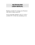
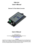
Unit Door Station User's Manual IHX-C1201 Series V1.1.0 Welcome Thank you for purchasing our product! This quick start guide is designed to be a reference tool for your system. Please keep it well for future reference! i Table of Contents 1 Overview ................................................................................................. ......... 1 2 Basic Functions............................................................................................... . 6 2.1 Call MGT center .................................................................................................. 6 2.2 Call Users ............................................................................................................ 6 2.2.1 Call Status ................................................................................................. 6 2.2.2 Communication status .............................................................................. 6 2.3 Monitor Function .................................................................................................. 6 2.4 Unlock Function ................................................................................................... 7 2.4.1 Unlock During the Dial Process ................................................................ 7 2.4.2 Unlock During the Communication ........................................................... 7 2.4.3 Unlock During the MON ............................................................................ 7 2.4.4 Unlock via the Password .......................................................................... 7 2.4.5 Unlock via IC card ..................................................................................... 7 2.5 Environment Light Compensation Function ........................................................ 7 2.6 Access Control (A&C) Function .......................................................................... 8 2.7 Vandal Proof Function ......................................................................................... 8 2.8 Approaching Induction......................................................................................... 8 3 Web Function .................................................................................................. . 8 3.1 Overview .............................................................................................................. 8 3.2 Basic Functions ................................................................................................... 9 3.2.1 Login Interface .......................................................................................... 9 3.2.2 System Settings ...................................................................................... 10 3.2.3 IHD Management ................................................................................... 13 4 Specifications ................................................................................................. 17 5 Device Port..................................................................................................... 18 6 Installation ...................................................................................................... 22 7 FAQ ................................................................................................................ 24 ii 1 Overview Connect the device to the power, the system boots up properly. After one minute, the screen turns on and the boot-up completes, system goes to the normal working interface. The front panel is shown as in Figure 1- 1 and Figure 1- 2. Figure 1- 1 Please refer to the following sheet for detailed information. 1 SN Name Function 1 Logo Decoration logo. 2 Photo Sensor 3 Compensation Light 4 Microphone It can detect the environment light. It is a compensation light option. It can compensate the camera light in the low illumination environments. Audio input 1. Button. a) Backspace function. It is to delete the previous symbol. b) Hang up function. It is to hang up the call. 2. Number button. Input the number 0 to 9. 3. 5 Key Panel button. When you are using the password to open the door. Press this button once to begin input. After you input the password, please press it again to complete the operation. 4. Call button. After you input the room number, press it to begin a dial up. 5. Call management (MGT) center button. Press it to call the MGT center directly. 6 Speaker Output audio 7 Card Induction zone Use the card to open the door. Here you can view prompt information, date, time and etc. Note: 1. “Call: Room No. + ↑ ”. Please input the room number first and then press the button to dial; 2.”Center: Press 8 LCD press the button button”. Please to call the MGT center. 3.“Unlock: + password + ”, If you want to open the door via the password, please press the button and then input the room number and password. Please press the button 2 to confirm. 9 3 Camera It is to monitor the video of the door. Figure 1- 2 Please refer to the following sheet for detailed information. SN Name Function 1 Logo Printed logo. 2 Microphone Audio input 3 Compensation Light It can compensate the camera light in the low illumination environments. 4 5 4 Approaching Induction Speaker It can detect approaching body. Output audio 1. Button. a) Backspace function. It is to delete the previous symbol. b) Hang up function. It is to hang up the call. 2. Number button. Input the number 0 to 9. 3. 6 Key Panel button. When you are using the password to open the door. Press this button once to begin input. After you input the password, please press it again to complete the operation. 4. Call button. After you input the room number, press it to begin a dial up. 5. Call MGT center button. Press it to call the MGT center directly. 7 Card Induction Zone Use the card to open the door. Here you can view prompt information, date, time and etc. Note: 1. “Call: Room No. + ”. Please input the room number first and then press the button to dial; 2.”Center: Press 8 button”. Please press LCD the button 3.“Unlock: to call the MGT center. + password + ”, If you want to open the door via the password, please press the button and then input the room number and password. Please press the button to confirm. 9 5 Camera It is to monitor the video of the door. 2 Basic Functions 2.1 Call MGT center In the standby status ( Figure 1- 1, Figure 1- 2), press or button, this IHX will call the MGT center. The video door phone begins when the MGT Port picks up. During the whole process, you can press the button or to end current dialogue and return to the standby interface. 2.2 Call Users 2.2.1 Call Status In the standby status, input the room number and then press the button or ,you can generate a call to the IHD of the user. During the process, you can press the button or to end current dialogue and return to the standby interface. 2.2.2 Communication status After you generated a call to the IHD, if there is response, you can enter communication status. It can realize the dual-way video phone. During the process, you can press the button or to end current dialogue and return to the standby interface. 2.3 Monitor Function The MGT Port and the IHD can both enable the monitor function which turns on the camera and monitors the device video. 6 2.4 Unlock Function 2.4.1 Unlock During the Dial Process During the dial process, the MGT Port or the IHD can open the door lock of the device remotely. System returns to the standby interface after phone hangs up or the countdown is complete. 2.4.2 Unlock During the Communication During the communication process, the MGT Port or the IHD can open the door lock of the device remotely. System returns to the standby interface after phone hangs up or the countdown is complete. 2.4.3 Unlock During the MON During the MON, the MGT Port or the IHD can open the door lock of the device remotely. System returns to the standby interface after phone hangs up or the countdown is complete. 2.4.4 Unlock via the Password In the standby status, press the button password. Press the button or or and then input the room number and to confirm the operation. The door is open if the password authentication is OK. 2.4.5 Unlock via IC card The door is open after you swipe IC card and the card passed the authentication and station verification. 2.5 Environment Light Compensation Function This device has the light compensation function when it is in the low illumination environments or it is at night. It includes the LCD backlight and the camera compensation light. 7 2.6 Access Control (A&C) Function The device can connect 1-channel door sensor input. It can be used to detect door status. There is 1-channel door on-off button to open/close the door. It has 2-channel control output. There are two modes: NO/NC. It can also be used for other general controls. Please refer to later sections for detailed information. 2.7 Vandal Proof Function There is 1-chahnel vandal proof button. System can generate an alarm once it is removed from the wall. At the same time, it can upload the alarm information to the MGT center. 2.8 Approaching Induction Only IHX-C1202B have this function. When there is any body approaching the IHX at a distance about 1 meter, screen backlight will be ON. 3 Web Function 3.1 Overview The web-based interface is shown in Figure 3- 1. Web function supports IHX-C1201 and IHX-C1202B. Here makes IHX-C1202B an example: 8 Figure 3- 1 Please refer to the following sheet for detailed information. SN Name 1 System Settings 2 Info Search 3 Status Statistics 4 Logout Function You can set IHX-C1202B device parameter and network info. You can search IHX-C1202B call history. You can perform statistics of IHD status under IHX-C1202B. You can control reboot of IHX-C1202B and shutdown of WEB server. 3.2 Basic Functions 3.2.1 Login Interface Input IHX IP address in address field of IE Explorer as in Figure 3- 2. 9 Figure 3- 2 You must input username and password in order to login WEB main interface. Default username: admin Default password: admin. After you login, you will see 4 major settings: system, info search, status statistics, and Logout. 3.2.2 System Settings System settings includes: local, IHD management, networking, network and password change. 3.2.2.1 Local Setting The following is the instruction for major settings: 1. Frame: For NTSC standard, please select 30 frame/s. For Pal standard, please select 25 frame/s. 2. One-key clear: You may restore all settings on IHX to default after pressing this button and confirm. Be careful! 3. Video format has two types of resolution: D1: 704x576 WVGA: 800x480 Please see Figure 3- 3. 10 Figure 3- 3 3.2.2.2 Access Control Management Click on local setting and then click on access control management. You may change password here and please keep in mind that the initial password is 123456. To unlock door, please input #123456#. You also can set unlock interval and duration. FTP address: FTP address is used to store snapshot taken at IHX when someone swipes card. User can login FTP to view those photos. 11 Figure 3- 4 3.2.2.3 System Time Click on local setting and then click on system time. You may set time in the following interface as in Figure 3- 5. You may also synchronize system time with your local PC. Figure 3- 5 12 3.2.3 IHD Management IHD management mainly includes add digital/analog IHD, delete IHD and edit IHD user. 3.2.3.1 Digital IHD Management In digital IHD management interface, check box display resident info enable to display successfully configured IHD info as shown in Figure 3- 6. Click on add button at the left lower corner, and input user name and IHD number. Please be notified that only IHD number is required for operation as default. Figure 3- 6 3.2.3.2 Analog IHD Management In analog IHD management interface, check box display resident info enable to display successfully configured IHD info as shown in Figure 3- 7. Click on add button at the left lower corner, and input IHD number, distributor address and distributor port. IHD number is the room number where analog IHD locates; distributor address is its dialup IP which ranges from 1 to 99. It originally could be manually adjusted, but now it has been burned into program. Port is the corresponding port number in distributor which normally is either 1~4 or 1~8, depending on number of distributor channel. For example, room number is 1502, distributor address is 15, and port NO. is 2. 13 Figure 3- 7 LAN Setting Default setting is enough if you just want networking between IHX and IHD, but if you want to set MGT center, you need to change default settings to be identical with MGT center info. You also need to check box register to the MGT center. If you successfully set MGT center, you may call MGT center by pressing call MGT center button at lower left corner on IHX. Please see Figure 3- 8. Figure 3- 8 Network Setting 14 In network setup interface, you can set IP parameter, IP address, subnet mask and default gateway of IHX as shown in Figure 3- 9. After you change IP address, WEB interface will reboot and you will see a new IP address interface. Figure 3- 9 Change Password In password change interface, you can change WEB login password of IHX. You must input old password, new password and confirm new password. Click on OK button to save as shown in Figure 3- 10. Figure 3- 10 Info Search Click on info search and then click on card history. Here you may search local call histories and device can store up to 1124 records. Please see Figure 3- 11 15 Figure 3- 11 Status Statistics Click on status statistics and then click on IHD status. Here you can view connection status of IHD as shown in Figure 3- 12. Figure 3- 12 Logout Click on Logout. Here you may select either to reboot device or Logout system as shown in Figure 3- 13 and Figure 3- 14. 16 Figure 3- 13 Figure 3- 14 4 Specifications Model IHX-C1201 OS Main Processor Embedded micro processor OS Embedded LINUX OS Video Video Compression Standard H.264 Input/Approaching Induction 1.3 megapixel CMOS camera Back Light Support Auto Light Compensation Audio Support Input Microphone 17 IHX-C1202B Output Built-in speaker Bidirectional Talk Support dual-way bidirectional talk Display LCD Dimensions 3-inch STN 3-inch screen screen Resolution Operation Mode 128*64 128*64 Input Digital keyboard Touch keyboard Card Built-in IC card induction reader Approaching Induction Body Approaching Not applicable 1 meter Alarm Vandal proof Access Control Support NO Output Support NC Output Support Door on/off Button Support Door Status Detect Support Network Ethernet 10M/100Mbps Self-adaptive Network Protocol TCP/IP Storage Memory 128MB Others Power DC 10~15V Power Consumption Standby≤1W ;work≤10W Working Environments -10℃~+60℃ 10~95%RH Water Proof IHX1212B-X Water proof level:IP65 Dimensions Weight 376mm*151mm*60mm(L*W*H) 1.6kg 5 Device Port The device rear panels are shown as in 5 - 1。 and Figure 5 - 2. 18 -40℃~+60℃ STN Figure 5- 1 IHX-C1201 rear structure Please refer to the following sheet for detailed information. SN Port Name 19 1 Network Port 2 Access Control Input Port 3 Analog Signal Port (IHX-C1201 only) Function Connect to the RJ45 port. Connect to signal from the door sensor, door on/off signal. Connect to the analog signal of the distributor. 4 Vandal Proof Alarm Button 5 RS422 Port (Reserved) 6 Power Port It can generate an alarm when there is a vandal operation. Connect to RS422 or RS485 Communication Device. Connect to 12V DC. Control NO/NC of door lock. 7 20 Access Control Output Port Figure 5- 2 IHX-C1202B rear structure Please refer to the following sheet for detailed information. SN Port Name Function 1 2 3 21 Vandal Proof Button Network Port Access Control Port Alarm It can generate an alarm when there is a vandal operation. Connect to the RJ45 port. Input Connect to signal from the door sensor, door on/off signal. 4 5 6 Power Port Access Output Connect to 12V DC power. Open or close the NO/NC lock. Control Port Analog Signal Port Connect to the analog signal of the distributor. Connect to RS422 or RS484 communication device. 7 RS485 Port 6 Installation Please refer to the following sheet for detailed installation information. Please see Figure 6- 1 and Figure 6- 2 IHX-C1202B installation guide. 22 Figure 6- 1 IHX-C1201 installation guide 23 Figure 6- 2 IHX-C1202B installation guide 7 FAQ Q: I cannot boot up the device, or I can see the LCD is black. A: Please check your power cable connection. Please reboot it again. Q: I cannot call. A: Please check your network connection. Q: I cannot reach the person I want to contact. What shall I do? A: It may be the network error. Please check the network cable connection between the host and the extension device. Q: The number I dial does not exist. A: Please make sure you have dialed the proper number. 24 Q: System says the IC card number is invalid when I swipe the card. What shall I do? A: The card status is abnormal. Please contact your administrator for help. Q: System says the IC card number is wrong. What shall I do? A: It means current card does not have the authority. Please contact your administrator for help. Q: I have some problems, I am not so sure or I can not fix. A: Please contact your local retailer for help. Note: This manual is for reference only. Slight difference may be found in user interface. All the designs and software here are subject to change without prior written notice. All trademarks and registered trademarks are the properties of their respective owners. If there is any uncertainty or controversy, please refer to the final explanation of us. Please visit our website or contact your local service engineer for more information. 25


![wireless Mini Keyboard-[2.4GHz] User`s Manual Ver:2.1](http://vs1.manualzilla.com/store/data/005666864_1-44f56227f4d883897f7b8660e8efda97-150x150.png)