1
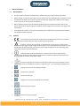
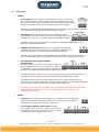
2014‐11‐21 Earth Leakage Monitoring System IsoBase | IsoHub | IsoOut User Manual Due to our policy of continual improvement, specifications may change without prior notice Megacon AB Ranhammarsvägen 20 – S‐168 67 Bromma – Sweden – Phone: +46 8 402 42 50 – [email protected] – www.megacon.se Page 2 (34) V1.6 Contents Earth Leakage Monitoring System ......................................................................................................................... 1 1 Before Installation .............................................................................................................................................. 3 1.1 Warning Notes ............................................................................................................................................. 3 1.2 Symbols ........................................................................................................................................................ 3 1.3 Connections ................................................................................................................................................. 4 1.4 Maintenance ................................................................................................................................................ 5 2 Technical Data .................................................................................................................................................... 6 3 IsoBase Appearance And Dimensions ................................................................................................................ 7 4 IsoHub/IsoOut Appearance And Dimensions ..................................................................................................... 8 5 Installation ......................................................................................................................................................... 9 5.1 IsoBase Mounting ........................................................................................................................................ 9 5.2 IsoHub/IsoOut Montage .............................................................................................................................. 9 5.3 System Description .................................................................................................................................... 10 5.3.1 IsoBase ............................................................................................................................................. 10 5.3.2 IsoHub .............................................................................................................................................. 11 5.3.3 IsoOut (optional module that is available for the IsoBase system revision 3.0 and higher) ............ 11 5.3.4 RS485 Communication ..................................................................................................................... 12 5.3.5 General Information ......................................................................................................................... 13 5.4 System Illustration ..................................................................................................................................... 14 5.4.1 Sample 1 ........................................................................................................................................... 14 5.4.2 Sample 2 ........................................................................................................................................... 15 5.4.3 Combination Of Sample 1 And Sample 2 ......................................................................................... 16 5.5 Typical Power Systems ............................................................................................................................... 17 5.6 Installation Procedure................................................................................................................................ 17 6 IsoBase Menus and options ............................................................................................................................. 18 6.1 Analogue Menu ......................................................................................................................................... 18 6.2 Input Menu ................................................................................................................................................ 18 6.3 Instant States Menu ................................................................................................................................... 19 6.4 Alarm Memory Menu ................................................................................................................................ 20 6.5 Instant Values Menu .................................................................................................................................. 21 6.6 Highest Values Menu ................................................................................................................................. 22 6.7 Lowest Values Menu: ................................................................................................................................. 23 6.8 TRMS/50Hz Values Menu (V4.0) ................................................................................................................ 24 6.9 THD/TRMS Values Menu (4.0) ................................................................................................................... 25 6.10 Event Memory Main Menu ................................................................................................................... 26 6.10.1 Event Memory Sub Menu ................................................................................................................ 27 6.11 Power‐up Memory Main Menu ............................................................................................................ 28 6.11.1 Power‐up Memory Sub Menu .......................................................................................................... 28 6.12 Info Menu.............................................................................................................................................. 28 6.13 IsoHub Communication Menu .............................................................................................................. 29 6.14 IsoOut Communication Menu ............................................................................................................... 29 7 Basic Settings Menu ......................................................................................................................................... 30 7.1 Set‐up Menu .............................................................................................................................................. 30 7.2 Settings Menu ............................................................................................................................................ 30 7.3 Languages Menu ........................................................................................................................................ 31 7.4 IsoHub‐COM and IsoOut‐COM Menu ........................................................................................................ 31 7.5 Date & Time Menu ..................................................................................................................................... 31 7.6 RS485‐PC‐Com Menu ................................................................................................................................. 32 7.7 Option Menu .............................................................................................................................................. 32 8 Menu cycle ....................................................................................................................................................... 32 8.1 Normal Mode Main And Sub Menus ......................................................................................................... 33 8.2 Configuration Mode Main and Sub Menus ................................................................................................ 34 9 Binary‐communication ..................................................................................................................................... 34 10 ModBus‐communication ........................................................................................................................... 34 Megacon AB Ranhammarsvägen 20 – S‐168 67 Bromma – Sweden – Phone: +46 8 402 42 50 – [email protected] – www.megacon.se 2(34) Page 3 (34) V1.6 1 Before Installation 1.1 Warning Notes Due to our policy of continual improvement, specifications may change without prior notice. Before making any high voltage or high current injections to your switchboard for insulation or circuit breaker fault condition trip test, please disconnect the power supply to the IsoBase unit and apply short circuit links to all CT (Current transformers). Before replacing any damaged components or adding any new components within this system, please disconnect the power supply to the IsoBase unit and apply short circuit links to all CT (Current transformers). If the equipment is used in a manner not specified by the manufacturer, the protection provided by the equipment will be impaired. 1.2 Symbols The CE marking means that the manufacturer himself demonstrates for the authorities that the product complies with the safety requirements within the EU. ! Indicates a warning of high voltage on the terminals. It also indicates a warning that before making any high voltage or high current injections on the switchboard for insulation or circuit breaker fault condition trip tests, please disconnect the power supply to the unit and apply short circuit links to all the current transformers. Indicates that the IsoBase instrument is a protected class I device. The protective conductor (PE =protected earth) must be connected. The instruments require this connection for filtering purposes of switch mode power supply. Illustrates the proper installation and connection of the CT (Current transformer) to the IsoHub input circuit. It also displays the correct assignment of L1, L2, L3 and Neutral through the CT. Keypad to activate the LCD display backlight. Warning state indicator. Alarm state indicator. Keypad to clearing the selected option or function. Menu orientation keypad. Numerical selection keypad. Megacon AB Ranhammarsvägen 20 – S‐168 67 Bromma – Sweden – Phone: +46 8 402 42 50 – [email protected] – www.megacon.se 3(34) Page 4 (34) V1.6 1.3 Connections IsoBase Power supply: These connections are located at the rear of the IsoBase unit. The system can be powered by a voltage range of 110-250 VAC/DC, 50-60 Hz that are connected to L (Line) and N (Neural). No other external power supplies should be connected to the system. A complete system requires 50VA. The protective conductor (PE =protected earth) must be connected. The instruments require this connection for filtering purposes of switch mode power supply. Relay Output: The relay outputs can be used to alert other systems concerning the active states. These connections are located at the rear of the IsoBase. The contacts are capable of switching max 500VA, 230VAC. The connections for warning and alarm relay outputs are marked with NC (Normally Close), C (Common) and NO (Normally Open). RS485 PC-Communication: The IsoBase unit is equipped with an RS485 communication port for connection to other IsoBase units within the same multidrop network that are connected to a host personal computer. This port can be used for remote readout of data and control of the system. You will find the necessary information regarding the communication protocol later on within this document. IsoHub/IsoOut Power Supply And RS485 Communication: The IsoBase unit provides the necessarily power supply for up to 8 IsoHub 16 channel units, this being the maximum number of units that can be connected to a single IsoBase. No other power supplies should be used for powering the IsoHub. The duplicated power terminals make it easier for multidrop connection of the IsoHub units, in applications where the IsoBase unit needs to be placed in the middle of the network. The RS485 connection is used to stabilise communication for readout of information and measurements between the IsoBase unit and the installed IsoHub devices. The duplicated RS485 terminals make it easier for a multidrop connection of the IsoHub units. Important: This communication interface is only assigned for communication between IsoBase and IsoHub/IsoOut and should not be mixed with RS485 PC-Communication or other communication networks. IsoHub CT Inputs: Up to 16 CT (Current transformer) can be connected to one IsoHub. Each input is clearly marked with its input number and connections. To each input two connections are assigned there polarity is insignificant. Power Supply and RS485 Communication: No other Power supply other than the one assigned at the IsoBase unit should be used to supply power the IsoHub units. This is provided by an internal 24VDC power unit. Megacon AB Ranhammarsvägen 20 – S‐168 67 Bromma – Sweden – Phone: +46 8 402 42 50 – [email protected] – www.megacon.se 4(34) Page 5 (34) V1.6 The duplicated power terminals make it easier for multidrop connection of the IsoHub units in applications where the unit needs to be placed in the middle of the network. The RS485 connection is used to stabilise communication for readout of information and measurements between the IsoBase unit and the installed IsoHub devices. The duplicated RS485 terminals make it easier for multidrop connection of the IsoHub units. Important: This communication interface is only assigned for communication between IsoBase and IsoHub/IsoOut and should not be mixed with RS485 PC-Communication or other communication networks. IsoOut (optional module that is available for the IsoBase system revision 3.0 and higher) Relay outputs: the IsoOut is equipped with 16 individual relay outputs, which can be used to alert other systems concerning the active input states. Each relay output is clearly marked with its output number and connections C (Common) and NO (Normal open). Power Supply and RS485 Communication: No other Power supply other than the one assigned at the IsoBase unit should be used to supply power the IsoOut units. This is provided by an internal 24VDC power unit. The duplicated power terminals make it easier for multidrop connection of the IsoHub units in applications where the unit needs to be placed in the middle of the network. The RS485 connection is used by the IsoBase unit to stabilise communication for information readout, measurements and control of the installed IsoHub and IsoOut devices. The duplicated RS485 terminals make it easier for multidrop connection of the IsoOut units. Important: This communication interface is only assigned for communication between IsoBase and IsoHub/IsoOut and should not be mixed with RS485 PC-Communication or other communication networks. 1.4 Maintenance Cleaning: If the unit needs to be cleaned, use only a dry cloth. Fuse failure: In case of a fuse failure, the units must be sent to the supplier for fuse change. Megacon AB Ranhammarsvägen 20 – S‐168 67 Bromma – Sweden – Phone: +46 8 402 42 50 – [email protected] – www.megacon.se 5(34) Page 6 (34) V1.6 2 Technical Data Languages: English, Swedish and German Power supply: IsoBase: IsoHub, IsoOut: Complete system: 110-250 VAC/DC max 10VA 50-60Hz 24 VDC max 5VA 82VA Accuracy: With current transformer G45 Range 0-100mA Trms (V4.0) +/-5% of scale Range 0,1-1A Trms (V4.0) +/-2% of scale Range 1-10A Trms (V4.0) +/-2% of scale Max. Input current 50-60Hz: <200A 200-500A 500-1000A Active low pass filter (V4.0): 60Hz, individually filter option/input Computer interface/protocol: RS485 multidrop network (Binary and ModBus protocol) Cycle time: 5 sec in order to monitor all 128 inputs Storage capacity: Input event memory: Power failure memory: 63 events per each input. 63 events. Relay outputs (IsoBase and IsoOut): Max 1A, 230VAC/DC change over contacts Fuse data: 4A slow 250V unlimited 40 seconds 5 seconds Dimensions and weight: IsoBase: IsoHub, IsoOut: WxHxD 5.67x5.67x4.53” (144x144x110 mm), 900 gr. The unit is mounted with 2 enclosed screws that are fitted in the rails on the sides or on the top and bottom of the unit. WxHxD 135 x 90 x 47 mm (incl.rail), 250 gr. The unit is DIN- rail mounted. Operating temperature: 32-158 F (0-70 C) Protection classification: IP 30 Max operation altitude: Max. 2000m Maximum relative humidity: 80% for temperatures up to 31 degree Celsius decreasing linearly to 50 relative humidity at 40 degree Celsius. Pollution degree: Pollution Degree 2 in accordance with IEC 664. Installation categories: IsoBase: IsoHub, IsoOut: Current transformers: Installation category I Installation category III Installation category III Operating environment: Indoor use only Recommended cable type: IsoBase RS485: IsoHub, IsoOut RS485/24VDC: IsoHub CT: <1200m Twisted-par shielded AWG24 (0,205 mm2) <200m 22 Twisted-par shielded AWG24 (0,205 mm2) <300m 22 Twisted-par shielded AWG22 (0,324 mm2) <450m 22 Twisted-par shielded AWG20 (0,519 mm2) <600m 22 Twisted-par shielded AWG18 (0,823 mm2) <900m 22 Twisted-par shielded AWG16 (1,31 mm2) <1200m 22 Twisted-par shielded AWG14 (2,08 mm2) FKAR-PG 20,5 mm2 Megacon AB Ranhammarsvägen 20 – S‐168 67 Bromma – Sweden – Phone: +46 8 402 42 50 – [email protected] – www.megacon.se 6(34) Page 7 (34) V1.6 3 IsoBase Appearance And Dimensions Megacon AB Ranhammarsvägen 20 – S‐168 67 Bromma – Sweden – Phone: +46 8 402 42 50 – [email protected] – www.megacon.se 7(34) Page 8 (34) V1.6 4 IsoHub/IsoOut Appearance And Dimensions Megacon AB Ranhammarsvägen 20 – S‐168 67 Bromma – Sweden – Phone: +46 8 402 42 50 – [email protected] – www.megacon.se 8(34) Page 9 (34) V1.6 5 5.1 Installation IsoBase Mounting The unit is mounted with 2 supplied screw clips that require fitting in the rails on the sides, top or bottom of the unit. All connections are made to the Wago-terminals at the rear. 5.2 IsoHub/IsoOut Montage Place the IsoHub against the DIN-rail, and snap it into the position shown in the figure. All connections are made to the Wago-terminals at the rear. Megacon AB Ranhammarsvägen 20 – S‐168 67 Bromma – Sweden – Phone: +46 8 402 42 50 – [email protected] – www.megacon.se 9(34) Page 10 (34) V1.6 5.3 System Description IsoBase Extended System, hereinafter referred to as IES, is a further development of the small standalone 12 channel earth leakage current monitoring system known as Isobox. The concept behind the IES system is to give the customer an opportunity to build a system for earth leakage current monitoring with up to 128 individual inputs, which is not possible with the existing commercial available systems. IES also makes it possible to measure the leakage current in one place and monitoring the results in a remote location on a graphical LCD-display. IES is constructed from two separate units, IsoBase & IsoHub : 5.3.1 IsoBase This unit, which is capable of controlling up to 8 IsoHub and 8 IsoOut units, can be placed up to 1200 metres from IsoHub/IsoOut units. The IsoBase unit contains the following features: A graphical LCD display with a resolution of 128128 pixels is used to display the measured values and settings of the system. The LCD display is also equipped with an EL-Backlight for illumination of operating the system during low ambient light conditions. Five pushbuttons for menu and optional orientation/control. 10 numerical pushbuttons for input selection. TRMS ”True Root-Mean-Squared” (V4.0). Individually active low pass filter option/input (V4.0). Two LED’s, one sum warning and one for sum alarm indication. One pushbutton for the LCD backlight. One pushbutton for reset/clear function. Integrated power supply for the whole distributed IES system. Depending upon the network distance, a four wire (no screen) or five-wire (with screen) interface to IsoHub/IsoOut units is required. Two wires for the serial RS485 communication (with or without screen) in a Multidrop bus network of IsoHub/IsoOut units and two wires for the power supply. (see cable Spec.) Two or Three-wire (including screen) RS-485 communication interface to a PC-Host. The IsoBase unit is designed to target and monitor up to 8 IsoHub and 8 IsoOut. All measurements and functions are displayed by a user-friendly menu interface. Use of a power fail sense, prevents data loss or corruption of the stored data within the instrument during a power failure. The unit is also equipped with a backup battery for maintaining stored data within the RAM and RTC clock, during any power failure. Only 5 seconds in order to scan & monitor all 128 inputs, which is 8 x distributed IsoHub/IsoOut units. Addressable communication protocol interface to a PC-Host. This enables the possibility of up to 8 x IsoBase units to be connected within a common multidrop RS484 network. Megacon AB Ranhammarsvägen 20 – S‐168 67 Bromma – Sweden – Phone: +46 8 402 42 50 – [email protected] – www.megacon.se 10(34) Page 11 (34) V1.6 5.3.2 IsoHub This unit, which has 16 inputs for earth leakage current measurement, can be placed up to 1200 metres from the IsoBase unit. The IsoHub unit contains the following features: The IsoHub will maintain its power from the IsoBase unit. 16 input channels for measurement of the input leakage current supplied by current transformers. Only one channel is measured at a time. All inputs are protected and limited for up to 200A primary summation current in the CT. TRMS ”True Root-Mean-Squared” (SN ≥ 516213000).. One green LED is used to indicate power. One red LED is used to indicate any acquired alarm. One yellow LED is used to indicate the streams of data communication between IsoBase unit and the IsoHub. Depending upon the network distance, a four wire (no screen) or five-wire (with screen) interface to IsoHub units is required. Two wires for the serial RS485 communication (with or without screen) in a Multidrop bus network of IsoHub units and two wires for the power supply. (see cable Spec.) Use of a Flash memory prevents input calibration errors, loss of data or corruption during any power failure. Each IsoHub unit has a unique serial No. which will be used by the system to install and stabilise communication with the IsoBase unit. 5.3.3 IsoOut (optional module that is available for the IsoBase system revision 3.0 and higher) This unit, which has 16 relay outputs can be placed up to 1200 metres from the IsoBase unit. The IsoHub unit contains the following features: The IsoOut maintains its 24VDC power from the IsoBase unit. 16 individual relay outputs, which can be used to alert other systems concerning the active input states. One green LED is used to indicate power. One red LED is used to indicate any acquired alarm. One yellow LED is used to indicate the streams of data communication between IsoBase unit and the IsoOut. Depending upon the network distance, a four wire (no screen) or five-wire (with screen) interface to IsoOut units is required. Two wires for the serial RS485 communication (with or without screen) in a Multidrop bus network of IsoOut units and two wires for the power supply. (see cable Spec.) Each IsoOut unit has a unique serial No. which will be used by the system to install and stabilise communication with the IsoBase unit. Megacon AB Ranhammarsvägen 20 – S‐168 67 Bromma – Sweden – Phone: +46 8 402 42 50 – [email protected] – www.megacon.se 11(34) Page 12 (34) V1.6 5.3.4 RS485 Communication The RS485 standard permits a balanced transmission line to be shared in a party line or multidrop mode. As many as 32 driver/receiver pairs can share a multidrop network the following system illustration samples show a typical two-wire shielded multidrop network. Note that the transmission line is terminated on both extreme ends of the line and not at drop points in the middle of the line. Termination is used to match impedance of a node to the impedance of the transmission line being used. When impedance is mismatched, the transmitted signal is not completely absorbed by the load and a portion is reflected back into the transmission line. If the source, transmission line and load impedance are equal these reflections are eliminated. To attain this with the IsoBase Extended System, both extreme ends of an RS485 communication network should be terminated with a 120 ¼ watt resistor. Do not combine/mix this communication line with the any other, including any IsoBase to PC link. They are totally independent from each other, the IsoHub/IsoOut RS485 network is used by the IsoBase for remote measurement readout and control of the connected IsoHub/IsoOut units. The IsoBase to PC RS485 network is use by a PC-Host for remote measurements readout from the connected IsoBase units. The maximum length of the RS485 should not exceed 1200Mtrs. Recommended cable types: IsoBase RS485: <1200m Twisted-par shielded AWG24 (0,205 mm2) IsoHub RS485/24VDC: <200m <300m <450m <600m <900m <1200m 22 Twisted-par shielded AWG24 (0,205 mm2) 22 Twisted-par shielded AWG22 (0,324 mm2) 22 Twisted-par shielded AWG20 (0,519 mm2) 22 Twisted-par shielded AWG18 (0,823 mm2) 22 Twisted-par shielded AWG16 (1,31 mm2) 22 Twisted-par shielded AWG14 (2,08 mm2) Megacon AB Ranhammarsvägen 20 – S‐168 67 Bromma – Sweden – Phone: +46 8 402 42 50 – [email protected] – www.megacon.se 12(34) Page 13 (34) V1.6 5.3.5 General Information The following information describes some of the functionality, expressions and conditions that are necessary to understand how the system operates. Warning: The instrument will immediately indicate a warning and activate the warning relay output when an input current exceeds it’s programmed warning threshold. The warning indication and warning relay output are not effected by the programmed delay time and will be automatically deactivated when any input no longer exceeds its programmed warning level Related chapter information:. 1.2 Symbols: Information regarding the warning indicator. 1.3 Connections: Information regarding the relay output. 6.2 Input Menu: Information regarding the relay output. 6.3 Instant States Menu: Information regarding the current active state. 7.2 Settings Menu: Information regarding adjustment of the active settings. Alarm: The instrument will indicate an alarm and activate the alarm relay output only when a input current (mA) exceeds the programmed alarm level continuously during the programmed delay time. The alarm indication and alarm relay output are the only functions which are effected by the programmed delay time and will stay activated until the all inputs in alarm no longer exceed the programmed alarm threshold and all alarm memories are manually cleared/reset. Related chapter information: 1.2 Symbols: Information regarding the warning indicator. 1.3 Connections: Information regarding the relay output. 6.2 Input Menu: Information regarding the relay output. 6.3 Instant States Menu: Information regarding the current active state. 7.2 Settings Menu: Information regarding adjustment of the current (mA) settings. Alarm Memory: The instrument uses this to indicate that the alarm state has occurred earlier for a particular input. To de-activate/confirm the alarm indicator and alarm relay output all alarm memory must be manually cleared/reset. Related chapter information: 6.3 Instant States Menu: Information regarding the current active state. 6.4 Alarm Memory Menu: Information regarding the alarm memory. IsoHub-Com Alarm: The instrument will also indicate an alarm when it can no longer stabilise communication with one of the installed IsoHub/IsoOut units after ten retries. Related chapter information: 1.3 Connections: Information regarding the IsoHub. 6.1 Analogue Menu: Information regarding the indication of IsoHub-Com Alarm. 6.11 IsoHub Communication Menu: Information regarding the active communication status. 6.12 IsoOut Communication Menu: Information regarding the active communication status. 7.4 IsoHub-Com Menu: Information regarding the current & active communication settings. 7.5 IsoOut-Com Menu: Information regarding the current & active communication settings. Sorting Method: The sorting method used within the IsoBase display menu is based on an ascending list input number and a descending list for all other information. Megacon AB Ranhammarsvägen 20 – S‐168 67 Bromma – Sweden – Phone: +46 8 402 42 50 – [email protected] – www.megacon.se 13(34) Page 14 (34) V1.6 5.4 System Illustration Sample 1 5.4.1 RS485/RS232 Converter A B RS232 3 Main RS485 Rt Up To 8 IsoHub And 8 IsoOut Units Can Be Connected Rt 1 3 2 4 IsoHub 1 3 1 IsoOut, optional module that is available for the IsoBase system revision 3.0 and higher 2 6 5 IsoHub 2 4 Rt 6 5 IsoOut 1 Rt The illustrated example shows the correct connection of a system where the IsoBase unit is installed as the first device in the installed multidrop IsoHub/IsoOut network. In this case the IsoBase is placed before IsoHub 1, which is followed, by IsoHub 2 and IsoOut 1. “Rt” Indicates the termination resistor, which is used to eliminate signal reflection on a RS485 multidrop network. This type of network most be terminated with a resistor of 120 in the far end of the network. Do not mix/combine the PC-RS485 network for IsoBase with the RS485 network assigned for the IsoHub/IsoOut. These communication interfaces are clearly marked and should be kept separate. As shown above, the RS485 and the 24VDC power supply to the IsoHub/IsoOut units are connected as a multidrop bus (In the sense that the RS485 and the 24VDC power supply is coming in to a device and leaving to the next device), no other power supply or connections should be made. The sample above, only illustrates a system of two IsoHub and one IsoOut units. The maximum limit is 8 IsoHub and 8 IsoOut per each IsoBase unit. A new IsoBase system and network can simply be added by connecting the new system to the same network marked as Main RS485 in above sample. Megacon AB Ranhammarsvägen 20 – S‐168 67 Bromma – Sweden – Phone: +46 8 402 42 50 – [email protected] – www.megacon.se 14(34) Page 15 (34) V1.6 5.4.2 Sample 2 Main RS485 RS485/RS232 Converter A B RS232 3 Rt Up To 8 IsoHub And 8 IsoOut Units Can Be Connected 4 1 2 Rt 3 1 IsoHub 1 2 6 IsoOut, optional module that is available for the IsoBase system revision 3.0 and higher 3 5 IsoHub 2 4 Rt 6 5 IsoOut 1 Rt The illustrated example shows the correct connection of a system where the IsoBase unit needs to be installed in the middle of an installed multidrop IsoHub/IsoOut network. In this case it is placed in-between the IsoHub 1 and IsoHub 2, followed by IsoOut 1. “Rt” Stands for termination resistor, which is used to eliminate signal reflection on a RS485 multidrop network. This type of network most be terminated with a resistor of 120 in the far end of the network. Do not mix/combine the PC-RS485 network for IsoBase with the RS485 network assigned for the IsoHub/IsoOut. These communication interfaces are clearly marked and should be kept separate. As shown above, the RS485 and the 24VDC power supply to the IsoHub/IsoOut units are connected as a multidrop bus (In the sense that the RS485 and the 24VDC power supply is coming in to a device and leaving to the next device), no other power supply or connections should be made. The sample above, only illustrates a system of two IsoHub and one IsoOut units. The maximum limit is 8 IsoHub and 8 IsoOut per each IsoBase unit. A new IsoBase system network can simply be added by connecting the new system to the same network marked as Main RS485 in above sample. Megacon AB Ranhammarsvägen 20 – S‐168 67 Bromma – Sweden – Phone: +46 8 402 42 50 – [email protected] – www.megacon.se 15(34) Page 16 (34) V1.6 5.4.3 Combination Of Sample 1 And Sample 2 Rt GND A RS485/RS232 Converter B PC Rt GND A B PC RS485 IsoBase 1 IsoHub RS485 IsoHub 24VDC GND A B GND A B - + - + GND A B GND A B - + - + RS485 24VDC IsoHub 1 1…………… Inputs …………16 a b …………………………….. a b Rt Rt GND A B GND A B - + - + RS485 24VDC IsoHub 1 1…………… Inputs …………16 a b …………………………….. a b GND A B GND A B - + - + RS485 24VDC IsoHub 2 1…………… Inputs …………16 a b …………………………….. a b Rt GND A B GND A B - + - + RS485 24VDC IsoOut 8 1……...… Relay outputs ………16 C NO …………………...….. C NO GND A B PC RS485 IsoBase 2 IsoHub RS485 IsoHub 24VDC GND A B GND A B - + - + GND A B GND A B - + - + RS485 24VDC IsoHub 2 1…………… Inputs …………16 a b …………………………….. a b Rt GND A B GND A B - + - + RS485 24VDC IsoOut 8 1……...… Relay outputs ………16 C NO …………………...….. C NO Megacon AB Ranhammarsvägen 20 – S‐168 67 Bromma – Sweden – Phone: +46 8 402 42 50 – [email protected] – www.megacon.se 16(34) Page 17 (34) V1.6 5.5 Typical Power Systems 5.6 Installation Procedure The following listed chapters guide you through the necessary information and procedures within this document for a correct installation of the system: 1.1 5.3 2 3 5.1 4 5.2 1.3 5.4 7 Warnings System Description Technical Data IsoBase Illustration and Dimensions IsoBase Mounting Instructions IsoHub/IsoOut Illustration and Dimensions IsoHub/IsoOut Mounting Instructions Connections System Illustration Basic Settings Megacon AB Ranhammarsvägen 20 – S‐168 67 Bromma – Sweden – Phone: +46 8 402 42 50 – [email protected] – www.megacon.se 17(34) Page 18 (34) V1.6 6 6.1 IsoBase Menus and options Analogue Menu The analogue menu displayed on the IsoBase screen will always show, by default, the input with the “Highest” current value (mA) across the network. This is also the menu to which the instrument will return if no operations have been made within 30 seconds. To display the value for any other input, enter the number of the required input, using the numerical keyboard followed by the “OK” key or simply using the left and right keyboard to increase or decrease the presented input number. Example: To present the value of input 128, press the key “1”, “2”, “8” and then “Ok”. The newly entered input number will be displayed replacing the current & active “Highest” or other displayed input number during the selection. To cancel the entered input number during selection press the “C” key. The information presented within this menu contains: Input number, followed by the input label. Current & active earth leakage values. Whether the input current value is the “Highest”. A filtered earth leakage current value is indicated by “mAF“. The active state for the displayed input such as “Ok”, “Warning” or “Alarm”. Whether the alarm memory active status has occurred, if so the active state changes to “Alarm Memory”. If the IsoBase unit is not able to stabilise any communication with the installed IsoHub/IsoOut units, the active state will change to “IsoHub-Com Alarm”. I n : 1 2 8 V a l u e : A B - C D - E H 5 0 0 m A F 1 0 0 m A H i g h e s t 5 0 0 A l a r m M e m o r y The clear button “C” is used to confirm and clear the alarm memory state for the displayed input. Use the up and down keyboard to display the next or previous menu. 6.2 Input Menu This menu will display all information corresponding to the selected input. To display any other input, enter the number required using the numerical keyboard followed by the “OK” key or simply using the left and right keyboard to increase or decrease the presented input number. Example: To present the value of input 128, press the key “1”, “2”, “8” and then “Ok”. The newly entered input number will be displayed replacing the active displayed input number during the selection. To cancel the entered input number during selection press the “C” key. The information presented within this menu contains: Input number. Input label. Current value. Current active State. The programmed delay time in seconds. The programmed alarm threshold. The programmed warning threshold. Active low pass filter option (V4.0). The number of any new events that have occurred since last control of the events occurred for the displayed input. Whether the input current value is the “Highest”. Whether the alarm state had occurred earlier. I n p u t : L a b e l : 1 2 8 A B - C D - E H V a l u e : S t a t e : 5 0 0 m A O K D A W F e l a i l a r l N e w a r n t y m i e : : n g : r : 5 2 0 0 0 1 0 0 0 A c t i s m A m A v e E v e n t s : 9 H i g h e s t I n p u t A l a r m M e m o r y The clear button “C” is used to confirm and clear the alarm memory state. Use the up and down key to display the next or previous menu. Megacon AB Ranhammarsvägen 20 – S‐168 67 Bromma – Sweden – Phone: +46 8 402 42 50 – [email protected] – www.megacon.se 18(34) Page 19 (34) V1.6 6.3 Instant States Menu The instant states menu is used to display the current active state. This information is presented as a collection of 8 inputs based on different data sorting modes. Use the left and right keyboard to display the next or previous 8 inputs. Note that the data sorting method applies to all existing inputs and not only the displayed input range. The information presented within this menu contains: The page number. The sorting method. Input number. Current active state. You are also able to use the numeric keyboard to provide a fast search of a specific input. Enter the number of the input using the numeric keyboard followed by the “OK” key. The IsoBase will then search for the page that contains that particular input and displays it. I n s t a n t S t a t e s P a g e I n p u t I n 1 2 3 4 5 6 7 8 S O O W O O A O O 1 S o r t e d t a t e k k a r n i n g k k l a r m k k Example: To display the state of input 128, press the key “1”, “2”, “8” and then “Ok”. The newly entered input number will be displayed on the last row as “keyboard: ”and the entered input number during the selection. To cancel the entered input number during selection press the “C” key. As an option you are able to use the “OK” key to change the arranged method or to display the input labels of the presented inputs. Its function is as follows: If the “OK” key is pressed and held for 3 seconds the menu I n s t a n t S t a t e s will change and present the labels corresponding to the displayed inputs. P a g e 1 When the Enter key is released the menu will change back to present the default menu. If the “OK” key is pressed only for a short period of time, less then 3 seconds, the menu will change the data sorting method. I n p u t I n 1 2 3 4 5 6 7 8 L A A A A A A A A a B B B B B B B B b - e C C C C C C C C I n s t a n t P a g e S t a t e The possible sorting methods are based on input number and highest priority states. S o r t e d I n 6 3 1 2 4 5 7 8 S A W O O O O O O l D D D D D D D D - E E E E E E E E 1 2 3 4 5 6 7 8 S t a t e s 1 S o r t e d t a t e l a r m a r n i n g k k k k k k Use the up and down key to display the next or previous menu. Megacon AB Ranhammarsvägen 20 – S‐168 67 Bromma – Sweden – Phone: +46 8 402 42 50 – [email protected] – www.megacon.se 19(34) Page 20 (34) V1.6 6.4 Alarm Memory Menu The alarm memory menu is used to display whether any alarm state has occurred earlier. This information is presented as a collection of 8 inputs based on different data sorting modes. Use the left and right keyboard to display the next or previous 8 inputs. Note that the sorting method applies to all existing inputs and not only the displayed input range. The information presented within this menu contains: The page number. The sorting method. Input number. Alarm Memory state. You are also able to use the numeric keyboard to provide a fast search of any specific input. Enter the number of the input using the numeric keyboard followed by the “OK” key. The IsoBase will then search for the page that contains that particular input and displays it. A l a r m M e m o r y P a g e I n p u t I n 1 2 3 4 5 6 7 8 S O O O A O A O O 1 S o r t e d t a t e k k k l a r m k l a r m k k M e m o r y M e m o r y Example: To display the state of input 128, press the key “1”, “2”, “8” and then “Ok”. The newly entered input number will be displayed on the last row as “keyboard: ”and the entered input number during the selection. To cancel the entered input number during selection press the “C” key. To clear all alarm memory, use the “C” key. As an option you are able to use the “OK” key to change the arranged method or to display the input labels of the displayed inputs. Its function is as follows: If the “OK” key is pressed and held for 3 seconds the menu will change and display the labels corresponding to the presented inputs. When the Enter key is released the menu will change back to present the default menu. A l a r m M e m o r y P a g e I n p u t I n 1 2 3 4 5 6 7 8 L A A A A A A A A a B B B B B B B B S o r t e d b - A l a r m 1 e C C C C C C C C The possible sorting methods are based on input number and highest priority alarm state memory. S t a t e I n 4 6 1 2 3 5 7 8 S A A O O O O O O - E E E E E E E E 1 2 3 4 5 6 7 8 M e m o r y P a g e If the “OK” key is pressed only for a short period of time, less then 3 seconds, the menu will change the data sorting method. l D D D D D D D D 1 S o r t e d t a t e l a r m l a r m k k k k k k M e m o r y M e m o r y To clear all alarm memory, use the “C” key. To display the next or previous menu, use the up and down keys. Megacon AB Ranhammarsvägen 20 – S‐168 67 Bromma – Sweden – Phone: +46 8 402 42 50 – [email protected] – www.megacon.se 20(34) Page 21 (34) V1.6 6.5 Instant Values Menu The instant menu is used to display the active current values and their relation to each particular input alarm threshold setting. This information is presented as a collection of 8 inputs based on different data sorting modes. Use the left and right keyboard to display the next or previous 8 inputs. Note that the sorting method applies to all existing inputs and not only the displayed input range. I n s t a n t V a l u e s P a g e The information presented within this menu contains: The page number. The sorting method. Input number. Current values. A filtered earth leakage current value is indicated by “mAF“. The relationship of the current active values to the alarm level settings. I n p u t I n 1 2 3 4 5 6 7 8 1 S o r t e d V a l u e 2 0 m A 3 0 m A 0 m A 0 m A 0 m A 0 m A 0 m A 1 0 0 m A R e l . 2 3 % 4 0 % 0 % 0 % 0 % 0 % 0 % 4 5 % F F You are also able to use the numeric keyboard to provide a fast search of any specific input. Enter the number of the input using the numeric keyboard followed by the “OK” key. The IsoBase will then search for the page that contains that particular input and displays it. Example: To display the instant values for input 128, press the key “1”, “2”, “8” and then “Ok”. The newly entered input number will be displayed on the last row as “keyboard: ”and the entered input number during the selection. To cancel the entered input number during selection press the “C” key. As an option you are able to use the “OK” key to change the arranged method or to display the input labels of the presented inputs. Its function is as follows: I n s t a n t V a l u e s If the “OK” key is pressed and held for 3 seconds the menu will change and display the labels corresponding to the P a g e 1 presented inputs. I n p u t When the Enter key is released the menu will change back to present the default menu. I n 1 2 3 4 5 6 7 8 L A A A A A A A A a B B B B B B B B S o r t e d b - e C C C C C C C C I n s t a n t If the “OK” key is pressed only for a short period of time, less then 3 seconds, the menu will change the sort method. I n 8 2 1 2 3 % Use the up and down key to display the next or previous menu. 3 4 5 6 7 - E E E E E E E E 1 2 3 4 5 6 7 8 V a l u e s P a g e V a l u e The possible sorting methods are based on input number, value and the relationship to the alarm threshold. l D D D D D D D D 1 S o r t e d V a l u e 1 0 0 m A 3 0 m A F F R e l . 4 5 % 4 0 % 2 0 m A 0 0 0 0 0 m m m m m A A A A A 0 0 0 0 0 % % % % % Megacon AB Ranhammarsvägen 20 – S‐168 67 Bromma – Sweden – Phone: +46 8 402 42 50 – [email protected] – www.megacon.se 21(34) Page 22 (34) V1.6 6.6 Highest Values Menu The highest values menu is used to display the absolute highest current level (mA) that each input has reached and the relationship to that particular input alarm threshold setting. H i g h e s t V a l u e s This information is presented as a collection of 8 inputs based on different data sorting modes. P a g e 1 Use the left and right keyboard to display the next or previous 8 inputs. Note that the sorting method applies to all existing inputs and not only the displayed input range. The information presented within this menu contains: The page number. The sorting method. Input number. Current highest value (mA). A filtered earth leakage current value is indicated by “mAF“. The relationship of the current active values to the settings. I n p u t I n 1 2 3 4 5 6 7 8 S o r t e d V a 2 3 2 5 0 3 0 1 l 0 0 0 0 0 0 3 1 0 0 u m m m m m m m m e A A A A A A A A R e l . 2 3 % 4 0 % 0 % 0 % 0 % 0 % 0 % 4 5 % F You are also able to use the numeric keyboard to provide a fast search of a specific input. Enter the number of the input using the numeric keyboard followed by the “OK” key. The IsoBase will then search for the page that contains that particular input and displays it. Example: To display the highest values for input 128, press the key “1”, “2”, “8” and then “Ok”. The newly entered input number will be displayed on the last row as “keyboard: ”and the entered input number during the selection. To cancel the entered input number during selection press the “C” key. As an option you are able to use the “OK” key to change the arranged method or to display the input labels of the presented inputs. Its function is as follows: If the “OK” key is pressed and held for 3 seconds the menu will change and display the labels corresponding to the presented inputs. When the Enter key is released the menu will change back to present the default menu. H i g h e s t V a l u e s P a g e I n p u t I n L a 1 A B 2 A B 3 A B 4 A B H i 5 g h e A s B 6 A B P a 7 A g B 8 A B V a l u e I n 8 2 1 3 4 5 6 7 1 S o r t e d b t e - e C C C C C C C C S l D D D D V D D D D o V a l 1 0 0 3 0 2 0 0 0 0 0 0 u m m m m m m m m e A A A A A A A A a 1 r F E E E E l E E E E t 1 2 3 4 u 5 e s 6 7 8 e d R e 4 4 2 l 5 0 3 0 0 0 0 0 . % % % % % % % % If the “OK” key is pressed only for a short period of time, less then 3 seconds, the menu will change the data sorting method. The possible sorting methods are based on input number, value and the relationship to the alarm threshold. Use the “C” key to reset/restart the registration of highest values for all inputs and up and down key to display the next or previous menu. Megacon AB Ranhammarsvägen 20 – S‐168 67 Bromma – Sweden – Phone: +46 8 402 42 50 – [email protected] – www.megacon.se 22(34) Page 23 (34) V1.6 6.7 Lowest Values Menu: The lowest values menu is used to display the absolute lowest current level (mA) that each input has reached and the relationship to that particular input alarm level threshold. This information is presented as a collection of 8 inputs based on different data sorting modes. Use the left and right keyboard to display the next or previous 8 inputs. Note that the sorting method applies to all existing inputs and not only the displayed input range. L o w e s t V a l u e s The information presented within this menu contains: The page number. The sorting method. Input number. Current lowest value (mA). A filtered earth leakage current value is indicated by “mAF“. The relationship of the current active values to the settings. You are also able to use the numeric keyboard to provide a fast search of a specific input. Enter the number of the input using the numeric keyboard followed by the “OK” key. The IsoBase will then search for the page that contains that particular input and displays it. P a g e I n p u t I n 1 2 3 4 5 6 7 8 1 S o r t e d V a 2 3 2 5 0 3 0 1 l 0 0 0 0 0 0 3 1 0 0 u m m m m m m m m e A A A A A A A A R e l . 2 3 % 4 0 % 0 % 0 % 0 % 0 % 0 % 4 5 % F Example: To display the lowest values for input 128, press the key “1”, “2”, “8” and then “Ok”. The newly entered input number will be displayed on the last row as “keyboard: ”and the entered input number during the selection. To cancel the entered input number during selection press the “C” key. As an option you are able to use the “OK” key to change the arranged method or to display the input labels of the presented inputs. Its function is as follows: L o w e s t V a l u e s If the “OK” key is pressed and held for 3 seconds the menu P a g e 1 will change and display the labels corresponding to the presented inputs. I n p u t When the Enter key is released the menu will change back to present the default menu. I n 1 2 3 4 5 6 7 8 L A A A A A A A A a B B B B B B B B S o r t e d b - L o w e s t If the “OK” key is pressed only for a short period of time, less then 3 seconds, the menu will change the sort method. Use the “C” key to reset/restart the registration of lowest values for all inputs and up and down key to display the next or previous menu. l D D D D D D D D I n 8 2 1 3 4 5 6 7 V a l 1 0 0 3 0 2 0 0 0 0 0 0 - E E E E E E E E 1 2 3 4 5 6 7 8 V a l u e s P a g e V a l u e The possible sorting methods are based on input number, value and the relationship to the alarm level. e C C C C C C C C 1 S o r t e d u m m m m m m m m e A A A A A A A A F R e 4 4 2 l 5 0 3 0 0 0 0 0 . % % % % % % % % Megacon AB Ranhammarsvägen 20 – S‐168 67 Bromma – Sweden – Phone: +46 8 402 42 50 – [email protected] – www.megacon.se 23(34) Page 24 (34) V1.6 6.8 TRMS/50Hz Values Menu (V4.0) The TRMS/50Hz menu is used to display the active current TRMS values and the filtered TRMS value for the 5060Hz setting. This information is presented as a collection of 8 inputs based on different data sorting modes. Use the left and right keyboard to display the next or previous 8 inputs. Note that the sorting method applies to all existing inputs and not only the displayed input range. T R M S / 5 0 H z The information presented within this menu contains: The page number. The sorting method. Input number. The TRMS value, if available on the connected IsoHub. The TRMS value after passing a low-pass filter (60-50HZ). You are also able to use the numeric keyboard to provide a fast search of any specific input. Enter the number of the input using the numeric keyboard followed by the “OK” key. The IsoBase will then search for the page that contains that particular input and displays it. V a l u e s P a g e I n p u t I n 1 2 3 4 5 6 7 8 1 S o r t e d T R M S 1 0 2 0 3 0 0 0 0 0 0 1 0 0 5 0 H z 1 0 0 0 m A 4 0 m A 0 m A 0 m A 0 m A 0 m A 0 m A 5 0 m A Example: To display the instant values for input 128, press the key “1”, “2”, “8” and then “Ok”. The newly entered input number will be displayed on the last row as “keyboard: ”and the entered input number during the selection. To cancel the entered input number during selection press the “C” key. As an option you are able to use the “OK” key to change the arranged method or to display the input labels of the presented inputs. Its function is as follows: If the “OK” key is pressed and held for 3 seconds the menu will change and display the labels corresponding to the presented inputs. When the Enter key is released the menu will change back to present the default menu. T R M S / 5 0 H z P a g e I n p u t I n 1 2 3 4 5 6 7 8 L A A A A A A A A a B B B B B B B B 1 S o r t e d b - e C C C C C C C C T R M S / 5 0 H z If the “OK” key is pressed only for a short period of time, less then 3 seconds, the menu will change the sort method. The possible sorting methods are based on input number, the TRMS value and the TRMS value passing a low-pass filter (60-50HZ). V a l u e s P a g e T R M S I n 1 8 2 3 4 5 6 7 T R M 1 0 2 1 0 3 l D D D D D D D D - E E E E E E E E 1 2 3 4 5 6 7 8 V a l u e s 1 S o r t e d S 0 0 0 0 0 0 0 0 5 0 H 1 0 0 0 5 0 4 0 0 0 0 0 0 z m m m m m m m m A A A A A A A A Use the up and down key to display the next or previous menu. If the connected IsoHub doesn’t support TRMS measurement no value will be displayed for the corresponded input and is been replaced with “------“. Megacon AB Ranhammarsvägen 20 – S‐168 67 Bromma – Sweden – Phone: +46 8 402 42 50 – [email protected] – www.megacon.se 24(34) Page 25 (34) V1.6 6.9 THD/TRMS Values Menu (4.0) The THD/TRMS menu is used to display the calculated total harmonic distortion and the TRMS value that the THD calculation is based on. This information is presented as a collection of 8 inputs based on different data sorting modes. Use the left and right keyboard to display the next or previous 8 inputs. Note that the sorting method applies to all existing inputs and not only the displayed input range. T H D / T R M S V a l u e s P a g e The information presented within this menu contains: The page number. The sorting method. Input number. The THD value, if available on the connected IsoHub. The TRMS value. You are also able to use the numeric keyboard to provide a fast search of any specific input. Enter the number of the input using the numeric keyboard followed by the “OK” key. The IsoBase will then search for the page that contains that particular input and displays it. I n p u t I n 1 2 3 4 5 6 7 8 1 S o r t e d T H D 1 0 0 % 3 0 % 0 % 0 % 0 % 0 % 0 % 1 0 0 % T R M S 1 0 0 0 m A 4 0 m A 0 m A 0 m A 0 m A 0 m A 0 m A 5 0 m A Example: To display the instant values for input 128, press the key “1”, “2”, “8” and then “Ok”. The newly entered input number will be displayed on the last row as “keyboard: ”and the entered input number during the selection. To cancel the entered input number during selection press the “C” key. As an option you are able to use the “OK” key to change the arranged method or to display the input labels of the presented inputs. Its function is as follows: If the “OK” key is pressed and held for 3 seconds the menu will change and display the labels corresponding to the presented inputs. When the Enter key is released the menu will change back to present the default menu. T H D / T R M S V a l u e s P a g e I n p u t I n 1 2 3 4 5 6 7 8 L A A A A A A A A a B B B B B B B B 1 S o r t e d b - e C C C C C C C C T H D / T R M S If the “OK” key is pressed only for a short period of time, less then 3 seconds, the menu will change the sort method. The possible sorting methods are based on input number, the THD value and the TRMS value. I n 1 8 2 3 4 5 6 7 - E E E E E E E E 1 2 3 4 5 6 7 8 V a l u e s P a g e T H D l D D D D D D D D 1 S o r t e d T H 1 0 2 1 0 0 3 0 0 0 0 0 0 D % % % % % % % % T 1 0 0 5 4 R 0 0 0 0 0 0 0 0 M m m m m m m m m S A A A A A A A A Use the up and down key to display the next or previous menu. If the connected IsoHub doesn’t support TRMS measurement no value will be displayed for the corresponded input and is been replaced with “------“. Megacon AB Ranhammarsvägen 20 – S‐168 67 Bromma – Sweden – Phone: +46 8 402 42 50 – [email protected] – www.megacon.se 25(34) Page 26 (34) V1.6 6.10 Event Memory Main Menu The event memory main menu is used to display the number of stored events within the IsoBase unit for each existing input. This information is presented as a collection of 8 inputs based on different data sorting modes. The maximum number of stored events for each input is limited to 63 events. Use the left and right keyboard to display the next or previous 8 inputs. Note that the data sorting method applies to all existing inputs and not only the displayed input range. The information presented within this menu contains: The page number The sorting method. Input number. Total number of existing events. The number of new events. The numeric keyboard is used to provide a fast search of a specific input and display of the event memory contents for a particular input. Enter the number of the input using the numeric keyboard followed by the “OK” key. The IsoBase will then search for the page that contains that particular input and displays it. If the current & active page contains that particular input the IsoBase will then display the contents of event memory for that particular input, refer to next section event memory sub menu. E v e n t M e m o r y P a g e I n p u t I n 1 2 3 4 5 6 7 8 1 S o r t e d T o t a l 9 0 2 0 0 0 1 0 3 0 N e w 2 0 0 0 0 0 0 5 Example: To display the event information for input 128, press the key “1”, “2”, “8” and then “Ok”. The newly entered input number will be displayed on the last row as “keyboard: ”and the entered input number during the selection. To cancel the entered input number during selection press the “C” key. As an option you are able to use the “OK” key to change the arranged method or to display the input labels of the presented inputs. Its function is as follows: If the “OK” key is pressed and held for 3 seconds the menu will change and display the labels corresponding to the presented inputs. When the Enter key is released the menu will change back to present the default menu. E v e n t M e m o r y P a g e I n p u t I n 1 2 3 4 5 6 7 8 L A A A A A A A A a B B B B B B B B S o r t e d b - E v e n t If the “OK” key is pressed only for a short period of time, less then 5 seconds, the menu will change the sort method. The possible sorting methods are based on input number, total number of events and the number of new events. Use the up and down key to display the next or previous menu. 1 e C C C C C C C C l D D D D D D D D I n 3 6 1 7 2 4 5 8 E E E E E E E E 1 2 3 4 5 6 7 8 M e m o r y P a g e T o t a l - 1 S o r t e d T o t a l 2 0 1 0 9 3 0 0 0 0 N e w 0 0 2 0 0 0 0 5 Megacon AB Ranhammarsvägen 20 – S‐168 67 Bromma – Sweden – Phone: +46 8 402 42 50 – [email protected] – www.megacon.se 26(34) Page 27 (34) V1.6 6.10.1 Event Memory Sub Menu The event memory sub-menu, which is a sub-menu within the Main Menu event memory, is used to display the stored events within the IsoBase unit for particular selected inputs. The maximum number of stored events for each input is limited to 63 events. Use the left and right keyboard to display the event memory sub menu for the next or previous input. The information presented within this menu contains: Input number Input label. The occurred state. The start date and time for that state. The maximum current value (mA) during the alarm state. E v e n t I n : 3 M e m o r y A B - C D - E 3 O k 0 6 . 0 1 . 2 0 0 2 Example: The displayed sample to the right should be interpreted A l a r m as: 0 6 . 0 1 . The input state from 06.01.2002 at 04:15 until now was/is W a r n i n “Ok”. 0 6 . 0 1 . The input state from 06.01.2002 at 04:10 until 06.01.2002 at 04:15 was “Alarm”, and the maximum value that the O k 0 6 . 0 1 . input current reached during this period was 728mA. The input state from 06.01.2002 at 04:05 until 06.01.2002 at 04:10 was “Warning”. The input state from 06.01.2002 at 04:00 until 06.01.2002 at 04:05 was “Ok”. And so on…. 4 : 1 5 2 0 0 2 7 2 8 m A 4 : 1 0 g 2 0 0 2 4 : 0 5 2 0 0 2 4 : 0 0 If there is an arrow shown on the display, use the up and down key to display the next or previous event. The numeric keyboard can be used to provide a fast display of event memory for another input. Enter the number of the required input using the numeric keyboard followed by the “OK” key. The IsoBase will then display the event memory for the selected input. Example: To display the event information for input 128, press the key “1”, “2”, “8” and then “Ok”. The newly entered input number will be displayed instead of the active displayed input number during the selection. To cancel the entered input number during selection press the “C” key. Each time an event memory sub menu for a particular input is displayed, the number of new events for that particular input within the main menu will be set to zero. To clear the entire event memory for the displayed input pressed and hold the “C” key for 3 seconds. Use the “Ok” key to leave the event memory sub menu. And left and right key to display the next or previous input. Megacon AB Ranhammarsvägen 20 – S‐168 67 Bromma – Sweden – Phone: +46 8 402 42 50 – [email protected] – www.megacon.se 27(34) Page 28 (34) V1.6 6.11 Power-up Memory Main Menu The power failure memory menu is used to display the last 63 power-up and power-off cycles of the system. The information presented within this menu contains: Total number of power failure. P o w e r - u p E v e n t To display the stored memory for power failure press “Ok” key to enter the power-up memory sub menu. M e m o r y C o u n t : 8 P r e s s O k T o e n t e r 6.11.1 Power-up Memory Sub Menu The information presented within this sub menu is: The power state. The date and time for occurred state. P o w e r - u p M e m o r y P o w e r O n 0 4 . 0 1 . 2 0 0 2 2 3 : 2 2 P o w e r O f f 0 4 . 0 1 . 2 0 0 2 2 3 : 1 0 To clear the entire power-up memory, pressed and hold the “C” key for 3 seconds. P o w e r O n 0 4 . 0 1 . 2 0 0 2 2 3 : 0 9 Use the “Ok” key to leave the power-up sub menu. P o w e r O f f 0 4 . 0 1 . 2 0 0 2 If an arrow shows on the display, use the up and down key to display the next or previous event. 2 3 : 2 2 6.12 Info Menu The Info menu is used to display the corresponding information regarding the unit model, type, version and the internal real time clock. I n f o The information presented within this menu contains: Time. Format: “hour:minute:second”. Date. Format: “Day.Month.Year”. If the auto daylight adjustment is activated. Communication protocol. Model. Type. Firmware version. D a t e M e n u & T i m e 0 : 1 4 : 5 4 5 . 0 1 . 2 0 0 2 D a y l i g h t A u t o P r o t o c o l : B i n a r y M o d e l : I s o B a s e T y p e : 2 0 0 2 V e r s i o n : 3 . 0 Use the up and down key to display the next or previous menu. Megacon AB Ranhammarsvägen 20 – S‐168 67 Bromma – Sweden – Phone: +46 8 402 42 50 – [email protected] – www.megacon.se 28(34) Page 29 (34) V1.6 6.13 IsoHub Communication Menu This menu is used to display the active used groups/channels and its communication status, each group is referring to an IsoHub unit with 16 inputs, connected as a multidrop network. The information presented within this menu contains: Unit index. Serial number for each IsoHub. The communication status. The arrow indicates communication attempts for a particular IsoHub unit. I s o H u b C o m m u n i c a t i o n U n i t The communication status displays the following information: OK: Installed and working fine. Error: Indicates no communication to the corresponding IsoHub unit. ----: Indicates that no unit is installed for that particular index. 1 2 3 4 5 6 7 8 H H H H H - - S t a t u s 0 0 0 0 0 - 0 0 0 0 0 - 0 0 0 0 0 - 1 2 3 4 5 - O O E O O - k k r r o r k k - Use the up and down key to display the next or previous menu. 6.14 IsoOut Communication Menu This menu is used to display the active used groups and its communication status, each group is referring to an IsoOut unit with 16 relay output, connected as a multidrop network. The information presented within this menu contains: Unit index, presents the boundary of the installed IsoOut outputs in connection to the IsoBase unit and the inputs. Index 1 corresponds for output 1-16, index 2 corresponds for output 17-32, index 3 …. and index 8 that correspond for output 113-128. Serial number for each IsoOut. The communication status. The arrow indicates communication attempts for a particular IsoOut unit. I s o O u t C o m m u n i c a t i o n U n i t 1 2 3 4 5 6 7 8 H H H H H - - S t a t u s 0 0 0 0 0 - 0 0 0 0 0 - 0 0 0 0 1 - 6 7 8 9 0 - O O E O O - k k r r o r k k - The communication status displays the following information: OK: Installed and working fine. Error: Indicates no communication to the corresponding IsoOut unit. ----: Indicates that no unit is installed for that particular index. Use the up and down key to display the next or previous menu. Megacon AB Ranhammarsvägen 20 – S‐168 67 Bromma – Sweden – Phone: +46 8 402 42 50 – [email protected] – www.megacon.se 29(34) Page 30 (34) V1.6 7 Basic Settings Menu To display the “Basic Settings Menu” press and hold the left, right and the enter key at the same time for 3 seconds. 7.1 Set-up Menu Use this menu to set some of the basic properties of the system. Use the keypad to select the following submenus. The presented information within this menu is: Settings, used to change the active input settings such as: Input label. S e t - u p M e n u Delay time. Alarm level. Warning level. > S e t t i n g s Languages, used to change the active used languages such L a n g u a g e s as: I s o H u b - C o m I s o O u t - C o m English. D a t e & T i m e Swedish. R S 4 8 5 - P C - C o m Norwegian. O p t i o n s German. R e t u r n The IsoHub communication, used to configure the connected IsoHub units. The IsoOut communication, used to configure the connected IsoOut units. The Date and Time, used to adjust the active date and time of the internal real time clock. The PC communication, used for configuration of the RS485 communication port. The Options, used for configuration of backlight and start menu. And the return option, used to leave the set-up menu. Use the up and down key to select a sub menu. An arrow to the left hand side will indicate the active selected menu. Press the “Ok” key to enter the selected sub menu. 7.2 Settings Menu s e t t i n g s Use this menu to customise some of the input properties. The editable properties are: Input number and label. Delay time. Alarm level. Warning Level. Active low pass filter (V4.0) The displayed properties corresponds to the displayed input number. If you require to change the properties for another input then the one displayed, you need to change the Input number. The IsoBase will then display the corresponding stored properties for that particular input. > I n p u t L a b e l D A W F e l a i l a r l a r n t S a v e S a v e M e n u 1 A B - C D - E 1 y m i n g e r 1 a l l 0 3 0 0 1 5 0 O s m A m A F F I n p u t s R e t u r n Selection of properties is carried out by using the up and down keys. To edit the selected properties press “Ok” key. This mode is indicated with the position of the arrow to the right hand side of the display. Use the numerical keypad to enter the new value for the Input, Delay, Alarm and Warning properties. And up and down key for character scroll of input label properties. To leave the edit mode press the “Ok” key. To save the new entered properties select the “Save” option and press the “Ok”. The instrument will confirm the save of the displayed properties for the active selected input by displaying “Ok” to the right hand side of the selected option. You are also able to save the active displayed properties for all inputs, simply by selecting the “Save all inputs”, this function will replace the delay, alarm and warning value for all inputs with the displayed ones. The input label properties will not be affected by this function. Use the “C” key to interrupt the edit mode. Megacon AB Ranhammarsvägen 20 – S‐168 67 Bromma – Sweden – Phone: +46 8 402 42 50 – [email protected] – www.megacon.se 30(34) Page 31 (34) V1.6 Languages Menu This menu gives you the opportunity to customise the currently used active language for displayed menus. Use the up and down key to select the desire language, and pres “Ok” to confirm your selection. L a n g u a g e s > E n g l i s h S w e d i s h N o r w e g i a n G e r m a n R e t u r n 7.3 IsoHub-COM and IsoOut-COM Menu Use this menu to install a new or remove an IsoHub/IsoOut unit connected to the IsoBase. All delivered IsoHub/IsoOut units are market with a nine digit serial number, the last four digit are used by the IsoBase to identify the IsoHub units within the same RS485 multidrop network. To install a new IsoHub/IsoOut unit select the first free group using the up and down key. Press the “Ok” key to select the edit mode. This is indicated by an arrow to the right hand I s o H u b - C o m M e n u side of the display. U n i t s Use the numerical keypad to enter the last four digits within the serial number of the required IsoHub/IsoOut unit and confirm it by pressing the “OK” key. The IsoBase will immediately try to stabilise communication with the device and displays the result as the status of that particular unit. To un-install any unit, select that particular IsoHub/IsoOut by using the up and down key and press the “C” key to remove the existing properties. 7.4 > 1 2 3 4 5 6 7 8 H H H H - - 0 0 0 0 - S t a t u s 0 0 0 0 - 0 0 0 0 - 1 1 1 1 - O O O O - k k k k - R e t u r n Date & Time Menu Use this menu to adjust the date and time of the internal Real Time Clock. You are also able to define the required daylight function. D a t e Use the up and down key to select an option, and press the ”Ok” key to select the edit mode. An arrow to the right hand side of the display indicates this. > H o u r M i n u t e S e c o n d Use the numerical keypad to enter the new value for the selected option, and confirm it by pressing the “Ok” key. Y e a r M o n t h D a y To change the daylight function, select this option and use the “Ok” key to activate or deactivate. & D a y l i g h t T i m e 0 4 2 4 1 6 2 0 0 2 0 1 0 5 A u t o R e t u r n Megacon AB Ranhammarsvägen 20 – S‐168 67 Bromma – Sweden – Phone: +46 8 402 42 50 – [email protected] – www.megacon.se 31(34) Page 32 (34) V1.6 7.5 RS485-PC-Com Menu This menu is used to define a proper logical address for the IsoBase unit in a multidrop network connected to a PC-Host, also for selection of the required baud rate. R S 4 8 5 - P C - C o m The selectable options within this menu are: Protocol: Binary, ModBus. Baud rate: 9600, 19200. Address: 1-255. Parity and format: Binary: None 8, N, 1 ModBus: Even 8, E, 1 Odd 8, O, 1 None 8, N, 2 None 8, N, 1 (V3.2) > P r o t o c o l B a u d B i n a r y r a t e 1 9 2 0 0 A d d r e s s 1 P a r i t y n o n e F o r m a t 8 , N , 1 R e t u r n Use the up and down key to select the address option. Press the “Ok” key to select the edit mode. An arrow to the right hand side of the option indicates this. Use the numerical keypad to enter the new logical number for the unit. And confirm it by pressing the “Ok” key. To change the baud rate for the RS485 communication, select the option and use the “Ok” key to change its value. 7.6 Option Menu This menu is used to define the backlight function and the start page for the IsoBase unit. The selectable options within this menu are: Backlight, used to specify the backlight function, selectable options are: Automatically: The instrument will light up the LCD as soon as any key is pressed. Manually: The instrument will light up the LCD only when the key backlight is pressed. Default Page, used to define the start page for the instrument, selectable options are: Analogue Page. Input Details. Instant States. Alarm Memory. Instant Values. Highest Values. Lowest Values. Event Memory. Power Memory. O p t i o n M e n u > B a c k l i g h t : A u t o m a t i c a l l y D e f a u l t P a g e : A n a l o g u e P a g e I s o O u t R e l a y : A l a r m R e t u r n IsoOut relay, defines the method used for activation of the relay outputs state, selectable options are: Alarm, the relay output follows the current state of the assigned input. Alarm memory, the relay output follows the alarm memory state of the assigned input. To clear the alarm memory please see chapter 6.4. Use the up and down key to select an option. Press the “Ok” key to change the alternative for the selected option. 8 Menu cycle The following pictures represent an overview of all possible menus included within the IsoBase menu system that can be displayed and monitored using the command keyboard. Megacon AB Ranhammarsvägen 20 – S‐168 67 Bromma – Sweden – Phone: +46 8 402 42 50 – [email protected] – www.megacon.se 32(34) Page 33 (34) V1.6 8.1 Normal Mode Main And Sub Menus Chapter Description 6.1 6.2 6.3 6.4 6.5 6.6 6.7 6.8 6.9 6.10 6.11 6.12 6.13-6.14 Analogue Menu Input Menu Instant States Menu Alarm Memory Menu Instant Values Menu Maximum Values Menu Minimum Values Menu TRMS/50Hz Values Menu THD/TRMS Values Menu Event Memory Main Menu Power-up Memory Main Menu Information Menu IsoHub/IsoOut Communication Menu Analogue Menu Input Menu Search Options Clear Label Sort X X X X X X X X X X X X X X X X X X X X Sub Menu X X X X X X X X X X X X X X X X X Ok Individual Input Selection Ok Individual Input Selection Instant States Menu Alarm Memory Page Selection Ok Sort Selection Page Selection Ok Sort Selection Input Selection Ok Ok Ok Input Selection Ok Label Display Label Display C Clear/Reset Instant Values Maximum Values Page Selection Ok Sort Selection Minimum Values Ok Input Selection Ok Label Display Input Selection Ok Label Display TRMS/50Hz Values THD/TRMS Values Page Selection Ok Sort Selection Event Memory Main Menu Ok Power-up Memory Main Menu Event Memory Sub Menu Ok Ok Ok Individual Input Selection Sub Menu Power-up Memory Sub Menu Information Menu Left and right keypad. Ok IsoHub/IsoOut Communication Menu Ok C Ok keypad short press <5 seconds . Up and down keypad. Ok Ok keypad long press >5 seconds. Numerical keypad and Ok key combination. Reset/Clear alarm memory. Megacon AB Ranhammarsvägen 20 – S‐168 67 Bromma – Sweden – Phone: +46 8 402 42 50 – [email protected] – www.megacon.se 33(34) Page 34 (34) V1.6 8.2 Configuration Mode Main and Sub Menus Index 7.1 7.2 7.3 7.4 7.5 7.6 7.7 Description Set-up Menu Input Settings Menu Languages Menu IsoHub Communication Menu Date And Time Menu RS485 PC-Communication Menu Option Menu Ok Left and right keypad. 7 Set-up Menu Ok Input Settings Menu Up and down keypad. Languages Menu Ok Ok keypad short press <5 seconds . IsoHub Communication Menu Ok Ok keypad long press >5 seconds. Date And Time Menu Ok Numerical keypad and Ok key combination. RS485 PC-Communication Option Menu 9 Binary-communication See separate manual. 10 ModBus-communication See separate manual Megacon AB Ranhammarsvägen 20 – S‐168 67 Bromma – Sweden – Phone: +46 8 402 42 50 – [email protected] – www.megacon.se 34(34)