1
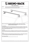
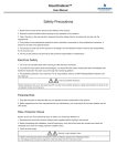
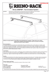
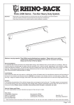
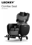
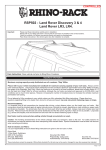
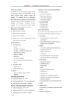
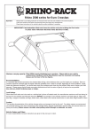
CONTROLLED
Rhino 2500 Series
Important:
1. Please refer to your fitting instruction to ensure that the roof racks are installed in the correct locations.
2. Check the contents of kit before commencing fitment and report any discrepancies.
3. Place these instructions in the vehicle’s glove box after installation is complete.
4. This kit also requires the DK fitting instructions
5. These instructions must be followed for warranty to be upheld.
Maximum carrying capacity: 75kg (165lbs) evenly distributed over crossbars. Please refer to your vehicle
manufacturers handbook and DK Specification sheet for maximum roof loading.
Always use the lower of the two figures.
Advisory:
It is essential that all bolt connections be checked after 48hrs from when you first install your crossbars. Bolt connections should
be checked again at regular intervals (once a week is enough, depending on road conditions, usage, loads and
distances travelled). You should also check the crossbars each time they are refitted. Make sure to fasten your load securely
(see page 2 for advisory diagrams). Please ensure that all loads are evenly distributed and that the centre of gravity is kept as
low as possible.
Use only non-stretch fastening ropes or straps.
Load Ratings
When these roof racks are to be used on a vehicle that is driven off sealed roads, the manufacturer maximum roof load rating (to
be found in the vehicle’s User Manual) should be divided by a safety factor of 2. For example, if the vehicle’s maximum roof
load rating is 75kgs\165lbs, these racks, when fitted to this vehicle should have no more than 37.5kgs/82lbs loaded on them.
Caution:
The handling characteristics of the vehicle changes when you transport a load on the roof. For safety reasons we recommend
you exercise extreme care when transporting wind-resistant loads. Special consideration must be taken into account when
cornering and braking. Please remove crossbars when putting vehicle through an automatic car wash.
Note for Dealers and Fitters:
It is your responsibility to ensure these fitting instructions are given to the end user or client
Rhino-Rack, 22 Hanson Pl, Eastern Creek
NSW 2766, Australia
Document No: 2501
(02) 8846 1900
Prepared By: K.Everett
Issue No: 11
rhinorack.com.au
Authorised By: Nicholas Clarke
Issue Date: 14/12/2018
These instructions remain the property of Rhino-Rack Australia Pty. Ltd. and may not be used or changed for any other purpose than intended.
Page 1 of 9
Rhino 2500 Series
!
!
km/h
!
The handling characteristics of the vehicle changes when you
transport a load on the roof. For safety reasons we recommend
you exercise extreme care when transporting wind-resistant
loads. Special consideration must be taken into account when
cornering and braking.
Although the system is tested and approved to AS1235-2000
/ ISO 11154, off-road conditions can be much more rigorous.
Extreme care must be taken in off road conditions
Paddle/ Surfboards should be fixed to the front of the
vehicle.
(A)
?
!
Page 2 of 9
Not recommended
(B)
Rhino 2500 Series
Use a Strap Retainer if positioned to the side as shown.
Paddle/ Surf boards to be rear facing and secure a strap around the fin and to the front of the vehicle.
Kayaks should
use additional
straps to secure
the load at the
front and rear
of the vehicle
where possible.
Always use
Kayak Carrier
Cradles when
transporting
Kayaks on the
roof.
Optimal Setup:
The Kayak should be
housed in Cradles
and held in place with
tension straps.
The front and rear of the
Kayak should be fixed
to the front and rear of
the vehicle. A Nose Tie
Down (RBAS1) should
be used to secure the
front of the Kayak.
Page 3 of 9
Rhino 2500 Series
Note: To complete installation, crossbars, leg and DK kits required. Be sure to have all three
before attempting to begin.
+
+
Crossbars
Legs
Pad & clamp (DK) kit
Parts List
Item
Component Name
Qty
Part No.
1
Rubber Buffer Strip
varies
M626
2
VA Crossbar
2
-
NOTE: Items 1-5 are packed within crossbar. 6 - 12 are
installed on legs
1
2
3
4a,b,c
5
3
M8 x 50mm Security Bolt
4
B154
4a
End Cap
4
M640
4b
Barrel
4
M622
4c
Key
2
M623
5
Measurement Strip
4
M641
6
M8 Pivot Nut
4
N047
7
Leg
4
M310
7
8
6
8
M6 Nut
4
N057
9
M6 Flat Washer
4
W031
10
M6 Spring Washer
4
W004
11
M6 x 20mm Socket Head
Screw
4
B054
12
Front Cover
4
M312
12
13
Key (x2 per kit) and Barrel
4
CA1339-BK
13
14
14
Foot Plate
4
M311
15
Torque Key
1
Torkey-L
16
Location Decals
4
S365
17
Positioning Decals
4
S364
18*
2500 Plastic Barrel
1-4
M313
19*
2500 Plastic Key
1-4
M314
20
Fitting Instructions
1
2501
Tools Required: Security Allen key, provided in kit. Tape
measure. Scissors.
9
10
11
15
Sold as
separate*
16
18
19
17
NOTE : Refer to the DK kit specification sheet for correct placement (Front & Rear, Left & Right) of the foot plate, rubber
pad and metal strap. Also refer for sizes to cut the bar measurement strips.
Page 4 of 9
Rhino 2500 Series
1
Open the Crossbar box and remove the end caps. Shake the crossbar up and down to remove measurement
strips and rubber buffer strips.
1.
2.
3
2
Install the Rubber Buffer Strips. Cut to size if
required.
4
The 2500 Legs will come with hardware assembled, however if the Pivot Nut is not attached to the leg, install
as shown with the angled face of the nut facing outwards (as below).
Leg will come assembled as shown.
Using the key provided, remove the Cover Plate
from the Legs.
Angled face of pivot
nut faces out.
Page 5 of 9
Rhino 2500 Series
5
Attach pad to foot plate.
Clip rubber pad onto foot plate. Pad central locator lug and end tabs must fully locate into the foot plate.
Refer to DK Kit Specificaton Sheet for correct orientation under pad/clamp numbers.
DK spec sheet.
DK001 Rhino-Rack VA, Aero, Euro & HD crossbar instruction
DK001 Rhino-Rack
,GHQWL¿FDWLRQ
IDENTIFICATION CHART
VA crossbar
IDENTIFICATION CHART
AERO crossbar
FRONT CROSSBAR
VA crossbar
EURO crossbar
AERO crossbar
EURO crossbar
VA
Vehicle
Date
Crossbar
EURO
AERO
AERO
HD
VA
EURO
AERO
HD
Front
Rear
Rear
Measurement
Measurement
Measurement Foot plate
Measurement Measurement Measurement
Foot plate
Left
Right
Left
strip length VA strip length
Distance HD arrow
strip length VA strip length
Distance HD arrow
Pad/
Pad/
Pad/
EURO
EURO
per side
per side
(x)
direction
per side
per side
(x)
direction
Clamp
Clamp
Clamp
Front
Front
Rear
Rear
Measurement
Measurement
Measurement Foot plate
Measurement Measurement Measurement
Foot plate
Right
M365 Right
M365 Left
M367 Left
strip length
strip length
Distance
arrow
strip length
strip length
Distance
arrow
Pad/
Pad/
114490 Pad/
114490 Pad/
per side
per side
(x)
direction
per side
per side
(x)
direction
114500 Clamp
Clamp
Clamp
Clamp
181mm
68mm
1010mm
OUT
181mm
68mm
1010mm
OUT
M367
Vehicle
Date
Crossbar
114500
05-11 1260mm
Arrow
M367
M367
FORWARD
114500 114500
Ford Focus 5dr
05-11 1260mm
181mm
68mm
1010mm
M367
M367
Hatch LS/LV
Arrow
114500 114500
Mitsubishi 380
FORWARD 191mm
05-08 1260mm
78mm
1030mm
OUT
4dr Sedan DB
Arrow
M367
M367
FORWARD
114500 114500
Mitsubishi 380
05-08 1260mm
191mm
78mm
1030mm
M367
M367
4dr Sedan DB
Arrow
Mitsubishi
114500 114500
FORWARD 191mm
Galant 4dr
04-07 1260mm
78mm
1030mm
OUT
Arrow
Sedan
M367
M367
FORWARD
Mitsubishi
114500 114500
Galant 4dr
04-07 1260mm
191mm
78mm
1030mm
Arrow
Sedan
FORWARD
Ford Focus 5dr
Hatch LS/LV
HD crossbar
REAR CROSSBAR
AERO
Front
Right
Pad/
Clamp
HD crossbar
REAR CROSSBAR
FRONT CROSSBAR
Arrow
M365
M365
FORWARD
114490 114490
OUT
181mm
68mm
1010mm
M365
M365
Arrow
114490 114490
FORWARD168mm
55mm
984mm
OUT
Arrow
M365
M365
FORWARD
114490 114490
OUT
168mm
55mm
984mm
M365
M365
Arrow
114490 114490
FORWARD168mm
55mm
984mm
OUT
Arrow
M365
M365
FORWARD
114490 114490
168mm
55mm
984mm
OUT
Arrow
FORWARD
OUT
OUT
OUT
End tabs.
Page 1 of 2
Central
locator lug
Page 1 of 2
VA
ot plate
arrow
rection
OUT
Rear
Right
Pad/
Clamp
Rear
Left
Pad/
Clamp
M365
114490
M365
114490
Arrow
FORWARD
M365
114490
Measur
strip le
per s
Central locator lug
pushes through.
181m
M365
114490
example only.
End tabs clip in.
Attach foot plate to leg.
With the pad correctly fitted to the
foot plate as per the DK spec sheet,
clip the foot plate onto the base of
the leg with the arrow facing In or
Out according to your vehicle
listed in the DK Kit specification
sheet.
R
DK spec sheet.
DK001 Rhino-Rack VA, Aero, Euro & HD crossbar instruction
DK001 Rhino-Rack
,GHQWL¿FDWLRQ
HD
IDENTIFICATION CHART
VA crossbar
IDENTIFICATION CHART
AERO crossbar
FRONT CROSSBAR
VA crossbar
EURO crossbar
AERO crossbar
EURO crossbar
Vehicle
Date
Crossbar
Front
Right
Pad/
Clamp
Front
Left
Pad/
Clamp
Front
AERO
AERO
HD
EURO
AERO
HD
Rear
Rear
Measurement
Measurement
Measurement Foot plate
Measurement Measurement Measurement
Foot plate
Right
Left
strip length VA strip length
Distance HD arrow
strip length VA strip length
Distance HD arrow
Pad/
Pad/
EURO
EURO
per side
per side
(x)
direction
per side
per side
(x)
direction
Clamp
Clamp
Front
Rear
Rear
Measurement
Measurement
Measurement Foot plate
Measurement Measurement Measurement
Foot plate
M365 Right
M365 Left
arrow
strip length
strip length
Distance
arrow
114490 Pad/
114490 Pad/
direction
per side
per side
(x)
direction
Clamp
Clamp
181mm
68mm
1010mm
OUT
M367 Right
M367 Left
Vehicle
Date
Crossbar
strip length
strip length
Distance
Pad/
Pad/
per side
per side
(x)
114500 Clamp
114500 Clamp
05-11 1260mm
181mm
68mm
1010mm
OUT
Arrow
M367
M367
FORWARD
114500 114500
Ford Focus 5dr
05-11 1260mm
181mm
68mm
1010mm
M367
M367
Hatch LS/LV
Arrow
114500 114500
Mitsubishi 380
FORWARD 191mm
05-08 1260mm
78mm
1030mm
OUT
4dr Sedan DB
Arrow
M367
M367
FORWARD
114500 114500
Mitsubishi 380
05-08 1260mm
191mm
78mm
1030mm
M367
M367
4dr Sedan DB
Arrow
Mitsubishi
114500 114500
FORWARD 191mm
Galant 4dr
04-07 1260mm
78mm
1030mm
OUT
Arrow
Sedan
M367
M367
FORWARD
Mitsubishi
114500 114500
Galant 4dr
04-07 1260mm
191mm
78mm
1030mm
Arrow
Sedan
FORWARD
Ford Focus 5dr
Hatch LS/LV
VA
VA
HD crossbar
REAR CROSSBAR
AERO
EURO
HD crossbar
REAR CROSSBAR
FRONT CROSSBAR
VA
Arrow
M365
M365
FORWARD
114490 114490
OUT
181mm
68mm
1010mm
M365
M365
Arrow
114490 114490
FORWARD168mm
55mm
984mm
OUT
Arrow
M365
M365
FORWARD
114490 114490
OUT
168mm
55mm
984mm
M365
M365
Arrow
114490 114490
FORWARD168mm
55mm
984mm
OUT
Arrow
M365
M365
FORWARD
114490 114490
OUT
168mm
55mm
984mm
Arrow
FORWARD
urement
tance
x)
Foot plate
arrow
direction
0mm
OUT
Rear
Right
Pad/
Clamp
Rear
Left
Pad/
Clamp
M365
114490
M365
114490
Measur
strip le
per s
OUT
OUT
OUT
Page 1 of 2
Page 1 of 2
Arrow
FORWARD
M365
114490
181m
M365
114490
example only.
Example:
Example:
Attach foot plate
to leg with arrow
facing IN.
Note: Facing IN
is for a small
number of
vehicles.
Attach foot plate
to leg with arrow
facing OUT
6
Decal.
Page 6 of 9
Leg location decals:
Stick the leg position labels inside the leg. The labels
identify the position of the leg on the vehicle roof. Use
as a guide when re-fitting the crossbars after removal.
Refer layout below.
Rhino 2500 Series
7
Measurement strip length:
Refer to DK Specification Sheet for cut length of bar measurement strips.
NOTE: front and rear bar generally have different lengths.
a. Accurately cut measurement strips to length. Slide into each end of crossbar. Repeat for front & rear crossbar.
b. Locate M6 nut into the crossbar then slide leg in to butt up against the measurement strip.
c. The measurement strip must butt up against the end of the crossbar cut out. Tighten M6 security screw
with the allen key provided. Tighten to 4-5 Nm (2-3 lb/ft)
a.
b.
c.
Push strip up against
end of cut out.
AERO
nt
ft
d/
mp
DK spec sheet.
67
500
VA
EURO
Measurement
strip length
per side
Measurement
strip length
per side
181mm
68mm
HD
Measure
Distan
(x)
Locate nut into
crossbar.
1010m
D
67
500
example only.
Length of measurement
strip is very important to
ensure proper fitment of
racks.
Note:
The measuring strip sits flush against
the leg as shown. Do not push the leg
over the strip.
With Torque Key
inserted, turn
clockwise until handle
straightens out as
shown.
Underneath
Leg
This indicates
4-5 Nm. More
pressure may
be required in
extreme climates.
4-5 Nm
Page 7 of 9
Rhino 2500 Series
8
10
9
Slide the remaining
measurement strip that
corresponds to the inside
length into the end of the
crossbar. Repeat this
for front and rear crossbars.
Cut strips flush with end of
crossbar if required.
Position roof racks:
Place racks onto the vehicle roof.
Refer to DK specification sheet for correct positioning of your roof racks.
A. Measure forward from where the front and rear doors meet/close.
B. Measure back to set distance between crossbars, centre of front foot plate
arrow to centre of rear foot plate arrow.
A and B measurements are to be in line with arrow in centre of foot plate.
B
DK spec sheet.
A
Front
11
Insert the end cap into the crossbar and
lock with key provided.
Arrow on foot plate.
Rear
Positioning decals:
Stick the white arrow decals in line with foot plate arrows onto the body work inside the door jamb. This marks
reference points for future use when racks are removed and then replaced.
Note:
When the door is shut, the sticker
should not be visible. Place accordingly.
Page 8 of 9
Rhino 2500 Series
12
Attach clamps:
Hook the lower part of the metal clamp in at the top of the
door jamb. Fasten M8 bolt to pivot nut.
Bolts must be tensioned evenly each side of the vehicle
to avoid pulling the rack to one side.
Tighten to 4-5 Nm (35-44 lbf.in). DO NOT OVER TIGHTEN.
Refer to DK instruction for correct clamp and pad combination
for front and rear of vehicle.
Check that the
assembly is tight
by shaking the
crossbars vertically
and horizontally
!
13
Visually inspect and ensure that the clamp is correctly seated against the body of the vehicle.
Side View: The clamp must have full contact along its face.
Clamp.
Vehicle.
14
Front cover key
or
- CA1344
Key #
15
Insert the two lugs on left side of front cover into
the leg. Use key provided to turn lock barrel to the
open position (O). Engage locking tab into leg.
Turn to close (C).
Open.
Plastic key - M314
*image
shown with
metal
keylock
Locks use a
slide window.
The cover
moves across
the face of the
barrel.
Closed.
*image shown with plastic keylock
Page 9 of 9