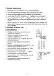
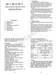
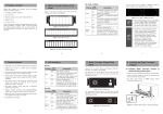
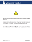
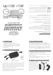
1
WARNING
1 - For the room air conditioner to operate satisfactory, install it as outlined in this installation
manual.
2 -Connect the indoor unit and outdoor unit with the room air conditioner piping and cords available
as standard parts. This installation manual describes the correct connections using the
installation set available from our standard parts.
3 - Installation work must be performed in accordance with national wiring standards by certified
persons only.
4 - Never cut the power cord, lengthen or shorten the cord, or change the plug.
5 - Also, do not use an extension cord.
6 - Plug in the unit firmly. If the receptacle is loose, repair it before using the room air conditioner.
7 - Do not turn on the power until all installation work is completed.
• Be careful not scratch the unit when handling it.
• After installation, explain, "CORRECT OPERATION" to the customer, using the
operation manual.
• Let the customer keep this installation manual to use when the room air conditioner is
served or moved.
• Before supplying the power, check the voltage measured by voltmeter is within ±10V.
Standard Accessories
The following installation accessories are supplied.
Use them as required.
(TABLE 1)
Qty
1
1
1
2
Mounting Plate.
Remote Control.
Remote Control
Holder.
Battery.
For indoor unit installation.
For air conditioner
operation
Use as remote
control unit
holder.
For
remote
control
unit.
Shape
Use
Selection the mounting position
Install at place that can withstand the weight of the indoor and outdoor units and install positively so
that the units will not topple or fall
Don’t install where there is the danger of combustible gas leakage.
Don’t install near heat sources or direct sun light.
Be sure that the indoor unit installs at height not less than 230 cm(90.6in), to sure that children less
than 10 years old not approach the unit.
-1-
Decide the mounting position with the customer as follows:
1. Install the indoor unit level on strong wall which not
subject to vibration.
2. The inlet and outlet ports should not be obstructed:
the air to be able to blow all over the room.
3. Install the unit near an electric source or special
branch circuit according to your national electrical
code.
4. Avoid any raise in condensate drain piping.
5. Avoid position where condensate cannot be easily
piped to an appropriate drain.
6. Avoid any unnecessary turns and bends in the
interconnection refrigerant pipes.
(TABLE 2)
A
6cm (2.4 in) or more
B
Left or Right Side 15 cm (5.9 in) or more
C
230 cm (90.6 in) or higher
Fig.1
A
B
C
Fig.2
Classic Series
H
W
Refrigeration & Drain
Connection
Refrigeration & Drain
Connection
W
H
Golden plasma Series
1
Refrigeration & Drain
Connection
H
W
2
-2-
Refrigeration & Drain
Connection
B
Indoors Dimensions:
(TABLE 3)
Classic Series
Indoor 07 : 17
Indoor 15 : 24
Indoor 30 : 36
W (mm-inch)
889(35)
1100(43.3)
1200(47.2)
H (mm-inch)
295(11.6)
335(13.1)
357(14.1)
(TABLE 4)
Golden Plasma
Design“1 or 2”
Indoor 007 : 015
Indoor 018 : 024
W (mm-inch)
818(32.2)
1090(42.91)
H (mm-inch)
292(11.5)
314(12.36)
Mounting plate (Dim in mm [inch])
Fig.3
Classic Indoor 07 : 17
530 [20,9]
300 [11,8]
115 [4,5]
286 [11,3]
80 [3,1]
266 [10,5]
115 [4,5]
Classic Indoor 30 : 36
Classic Indoor 15 : 24
979 [38,5]
550 [21,7]
280 [11,0]
191 [7,5]
287 [11,3]
420 [16,5]
89 [3,5]
56 [2,2]
735 [28,9]
375 [14,7]
410 [16,1]
700 [27,5]
Golden Plasma series “B”
Indoor 007 : 015
Golden Plasma series”B”
Indoor 018 : 024
552 [21,7]
470 [18,5]
243 [9,6]
285 [11,2]
540 [21,3]
334 [13,1]
60 [2,4]
72 [2,8]
404 [15,9]
72 [2,8]
-3-
(Rear)
Fig. 4
5-Left Outlet
2-Right outlet
4-Left Rear Outlet
1-Rear Outlet
3-Bottom Outlet
Starting installation:
Mounting the installation plate (wall hook bracket) according figs. (1, 2, 3) on the wall
horizontally.
Drill a hole in the wall on either the left or right side of the installation plate for
refrigerant pipes, drain and Electrical cables; the hole should have a slight inclination to
the outside direction.
Let the hole be 70 -80 mm(2.8-3.1in) diameters and you must use PVC sleeve.
Extend the sleeve by length10 – 15 mm (0.4-0.6in) from the outside direction, See Fig. 6.
Fasten the wall hook to the wall with 6 or more screws through the holes near the
outer edge.
Fig. 5
Center mark
Fig.6
Lower
Lower
10mm or
over
Fasten with
vinyl tape
10mm or over
100mm dia.
hole
5 to 10mm low
(Wall pipe)
Outside
Weight
Inside
Wall
CAUTION
IF the wall hook bracket not stalled horizontally and perpendicularly & if the hook
bracket is titled, drain water will drip to the floor.
-4-
TABLE (5)
Flare nut tightening torque:
Fig. 7
Flare nut
Tighten with two wrenches
6.35 mm.
Dia.(1/4")
Wrench (fixed)
Flare nut
12.7 mm.
Dia.(1/2”)
Torque
wrench
Connection pipe
Indoor unit pipe
To prevent gas leakage,
coat the flares surface with
refrigerator oil.
9.52 mm.
Dia.(3/8”)
15.88
mm.
Dia.(5/8")
19.05 mm.
Dia.(3/4")
Tightening torque
(14.7 to 19.6)N.m
(150 to 200)Kgf.cm
(10.84 to 14.46) Ib-ft
(49.00 to 55.86)N.m
(500 to 570)Kgf.cm
(36.13 to 41.19) Ib-ft
(34.3 to 39.2)N.m
(350 to 400)Kgf.cm
(25.29 to 28.93) Ib-ft
(73.6 to 75.80)N.m
(750 to 800)Kgf.cm
(54.28 to 57.89) Ib-ft
(98.00 to 130.00)N.m
(1000.00 to
1325.60)Kgf.cm
(72.28 to 95.88) Ib-ft
CAUTION
Do not remove the cap from the connection pipe before connecting.
You must use two wrenches one of them torque according the table (2) and (Fig. 7).
Put the indoor unit over the hook wall plate by engaging the two hooks of the indoor
unit their positions in the installation plate.
Check that the hooks are securely seated in their position by trying to move the unit.
Check that the unit is fully rested on the wall as shown.
Fig. 8
Connections pipes
Bend (R100) with a pipe bender
When extending the drain hose at the indoor unit, install the
accessory drain insulation.
Fig.9
Fig.10
Drain insulation
Indoor unit drain hose
Vinyl tape
Drain hose
Place the indoor unit drain hose behind the piping.
-5-
Electric Wiring Diagram:
(007: 017) models
"Cool Only" Unit
N C
"Heat Pump" Unit
Indoor Unit
N
N C Outdoor Unit
C
W CF
N C
W CF
220 - 240/1/50Hz
110 - 115/1/60Hz
N
C
CF
W
Neutral
Control Cool
Condenser Fan
Control Heat
Defrost Sensor
Cable
In case of 208-230/1/60: L1≡ N
(015 : 024) models
"Cool Only" Unit
"Heat Pump" Unit
Outdoor Unit
N C
N L C
Indoor Unit
Safety Breaker
N C
W CF
N
C
L
W CF
Defrost Sensor
Cable
Safety Breaker
220-240/1/50Hz
(020: 036) models
"Cool Only" Unit
B Y C
N L B Y C
"Heat Pump" Unit
Indoor Unit
Safety Breaker
Ground Leakage
Breaker
N
Outdoor Unit
L
B
Y
C
W CF
B
Y
C
W
Safety Breaker
220-240/1/50Hz
208-230/1/60Hz
Ground Leakage
Breaker
-6-
CF
Defrost Sensor
Cable
(018 : 024) models
"Cool Only" Unit
L1 C
L1 L2 C
"Heat Pump" Unit
Outdoor Unit
L1 C
W CF
Indoor Unit
L1 L2
C
Safety Breaker
W CF
Defrost Sensor
Cable
Safety Breaker
208-230/1/60Hz
(030 : 036) models
"Heat Pump" Unit
"Cool Only" Unit
B Y
L2 L1 B
Y
C
Indoor Unit
C
L2 L1
B
Y
C
W CF
B
Y
C
W CF
Outdoor Unit
Safety Breaker
208-230/1/60Hz
Safety Breaker
Defrost Sensor
Cable
Fig. 10
* In some cases, the indoor terminal block contains: B(indicated to live) and Y(indicated to neutral)
instead of (L) and (N).
Terminal cover
Tapping screw
Type A
Type B
Terminal cover
Fig.11
Wiring Connection:
1.
2.
3.
4.
5.
Remove the intake grill.
Remove the terminal cover as (type A) or (type B).
Remove the clamp.
Match the terminal block numbers and connection colors with those of the outdoor unit.
Connect the connection cords firmly to the terminal block. Imperfect installation may cause
afire "see fig.16".
6. Always connect the ground wire.
7. Fasten the connection cord with the cord clamp.
8. Fasten the terminal cover.
-7-
Outdoor Unit Installation:
min. 1000 mm
[39.4 inch]
[19.7 inch]
min. 500 mm
min. 250 mm
[9.8 inch]
If possible, don’t install the unit where it will be exposed to direct sunlight.
Don’t install the unit where a strong wind blows or where it is very dusty.
Take you neighbors into consideration so they are not disturbed by air blowing into there
windows or by noise.
Flow the dimensions as shown below.
Don’t set the unit directly on the ground because it will cause trouble.
min 700 mm
[27.6 inch]
min. 200 mm
[7.9 inch]
min. 700 mm
[27.6 inch]
[39.4 inch]
min. 1000 mm
NO !
[19.7 inch]
min. 500 mm
Service area required
[118.1 inch]
min. 3000 mm
[15.7 inch]
min. 400 mm
[59.1 inch]
min. 1500 mm
Air flow direction
All Dim. in m.m.[inch]
Refrigerant Pipe Work:
CAUTION
The maximum lengths of piping is shown in the Table 6 if the unit are further apart
than this, correct operation cannot be guaranteed.
-8-
TABLE (6)
Equivalent
Length
m
1-6
6 - 12
12 - 16
16 – 24
24 - 30
ft
3 - 20
20 - 40
40 - 54
54 - 80
80 - 100
Model Name
Classic Indoor 07 – 09
Golden Plasma series
“B” Indoor 007 - 009
“R22”
Classic Indoor 12 – 17
“R22” Golden Plasma
series”B” Indoor 007 :
012 “R407”
S
L
S
L
S
L
S
L
9.5
(3/8”)
6.4
(1/4”)
12.7
(1/2”)
6.4
(1/4”)
12.7
(1/2”)
6.4
(1/4”)
15.9
(5/8”)
9.5
(3/8”)
15.9
(5/8”)
9.5
(3/8”)
15.9
(5/8”)
9.5
(3/8”)
19
(3/4”)
9.5
(3/8”)
19
(3/4”)
9.5
(3/8”)
19
(3/4”)
9.5
(3/8”)
19
(3/4”)
9.5
(3/8”)
22.2
(7/8”)
12.7
(1/2”)
22.2
(7/8”)
12.7
(1/2”)
S
L
22.2
(7/8”)
12.7
(1/2”)
Classic Indoor15
Golden Plasma Indoor
018 : 024
Classic Indoor 20*
Classic Indoor 24*
Classic Indoor 30 : 36
Where S: is the suction line diameter .in mm (in") & L: is the liquid line diameter in mm (in")
Insulating the pipes:
Both liquid and the suction pipes must be insulated separately by a heat resistance
material such as Polyethylene foam with a heat transfer rate of 0.035–0.045 kcal/m h
c˚(0.14-0.18BTU/h) and with a thickness of 8-10mm(0.31-0.4in).
* For Indoor 20/Outdoor 20GO The max. length is 20 meter (66 feet). & Indoor 24/Outdoor 25GO
The max. length is 24 meter (80 feet).
Preparing pipes:
Suction Line
Electric Cables &
De-frost sensor
cable
L
Liquid Line
Check if (L) is flared uniformly
and not cracked or scratched
Drain Hose
Fig.12
•
•
•
•
•
•
•
•
•
Cut the connection pipe to the necessary length with pipe cutter.
Hold the pipe downward so that cuttings will not inter the pipe and remove the burrs.
Insert the flare nut onto the pipe and flare the pipe with flaring tool.
When bending the pipe, be careful not be crush it.
To prevent crushing of the pipe, don’t bend the pipe at radius curvature of 100 mm
(3.9in) or more.
If the copper pipe is bent or pulled to often, it will become stiff.
Don’t bend the pipe more than three times at one place.
Connect the outdoor and indoor piping.
After matching the center of the flare surface tight the flare nut by hand, then tight the
nut to specified tightening.
-9-
The flaring tools cone-shaped adapter
stretches the end of the tubing and forces it
against the chamfer forming a 45˚ flare.
Correctly made flare is vital to achieving a
leak proof connection. A- Correctly made
flare,B-Flare too small, C- Flare too large,DFlare uneven.
Fig.14
Fig.13
Fig.15
Air Vacuum:
1. Remove the cap; connect the gauge manifold and vacuum pump to the charging valve by
service hoses "see fig.18".
2. Vacuum the indoor unit and the connecting pipes until the pressure in them lowers to
below1.5 mmHg (-30 inHg), keeping vacuum process for 10 minutes at least.
3. Disconnect the service hoses and fit the cap to charging valve.
4. Remove the blank caps, and fully open the spindles of the 2way or 3way valve with
Hexagonal wrench (torque 70 - 90 kgf.cm = 516.29 - 663.8 Ib-ft) for 2way valve & 100 - 120
kgf.cm = 737.56 - 885.7 Ib-ft) for 3way valve.
5. Tighten the blank cap to specified torque (200 – 250 kgf.cm = 1475.12 - 1843.9 Ib-ft) See
Fig. 17.
Additional Charge:
The unit design considered the pipes equivalent length between indoor and outdoor is 4 meter. For
more pipes length add the additional charge as mentioned at table(7) .
TABLE (7)
Charge
R22/R407C
Gm/m
Classic Indoor 0709
Golden Plasma
series “B” Indoor
007 : 010
Classic Indoor 12-17
Golden Plasma
series “B” Indoor
012 - 015
Classic Indoor 15 :
24
Golden Plasma
series “B” Indoor
018 : 024
Classic Indoor 30 :
36
20
25
30
45
- 10 -
Note: In case R407C
1. Never add additional charge to increase the R407C of leakage system, the leakage
system must be repair first and recharge.
2. During initial charging, R407C must be removed from the charging cylinder in the liquid
phase.
R407C is a new refrigerant which prevent Ozone layer destruction.
Connection pipe
Terminal cover
Blank cap
Outdoor unit
Service hose with
valve core
Cord clamp
3-way valve
Charging port
Hexagon wrench
Cap
Insulation tube
Fig.16
Fig.17
Gauge manifold
Vacuum
pump
Service hose
Fig.18
(1)Insulate between pipes.
For rear,right,and bottom piping overlap the connection pipe heat insulation and indoor unit pipe heat
insulation and bind them with vinyl tape so that there is no gap.
For left and left rear piping, put the connection pipe heat insulation and indoor unit pipe heat insulation
together and bind them with and vinyl tape so that there is no gap.
Connection pipe
Overlap the insulation
Indoor unit pipe
Cloth tape
Connection pipe
(Heat insulation)
Vinyl tape
Indoor unit pipe
Bind the pipes together so that there is no gap.
Wrap with cloth tape
• For left and left rear piping, bind the
connection cord to the top of the pipe
Connection cord
Pipe
Vinyl tape
Fig.19
- 11 -
• For left and rear piping, bundles the piping
and drain hose together by wrapping them
with cloth tape over the range.
Check That:
GOOD
BAD
BAD
BAD
Drain
Hose
Saddle
Lifted up
Wave
End in water
Fig.20
Developed Air Filters "For Golden Plasma series “B” only
Our units built a great reputation on developing air purifiers system with a carbon and plasma filters
technique which is more efficient than conventional purifiers cleaning system.
Passive air filtration with active air treatment to achieve healthier environment.
Plasma filters:
−
Plasma technology depends on emitting the negative ions - released by high
voltage techniques - like those responsible for purifying the air in the nature
by inactivated the effects of chemical components of the odors, mold
spores….etc.
− It is effective against:
1-Viruses
2-Floating Mold Spores (as nitrogen oxide from cigarette smoke)
3-Odors (as cigarette smoke, garbage and toilet).
Installation Procedure:
12345678-
Turn the power-supply off.
Open the unit front grill
Remove the air filters.
Remove the unit front cover.
Install the plasma filter electric black block into the Electric box.
Fasten the bag filter in front of the coil by screws.
Connect the Plasma filter wire as wiring bellow.
Return the front cover and air filters.
- 12 -
Electric Wiring Connection:
Limit Switch
N
C
NO
Connector
COM NC
To Plasma
Filter
Plasma Filter Cleaning Procedures:
123456-
Turn the power-supply off.
Open the unit front grill
Remove the front cover and air filters.
Remove the plasma filters.
Drip the filters on water mixed with neutral detergent vessel for 20 minutes .
Dry up the filters in the shade for a day (be sure that the humidity is removed
perfectly).
7- Return the front cover and air filters.
Carbon Filter:
Carbon filter is an active filter in dealing with odors. It is remove the Pet hair odor , Toilet
odor, garbage odor,…etc.
Installation Procedure:
12345-
Turn the power-supply off.
Open the unit front grill.
Remove the Air filters.
Slide them in the front cover filter guide.
Return the air filters.
Carbon Filter Cleaning Procedures:
123456-
Turn the power-supply off.
Open the unit front grill.
Remove the Air filters.
Remove the carbon filters.
Keep them in the sun shine for two hours.
Return the air filters.
Test running:
Connect the power supply to the unit; a circuit breaker is required in the power supply line.
Prepare the remote controller for option by installing the accessory battery in their place (see
instruction in User Manual).
Test the operating voltage at the power terminal block on the unit, and check that it accords with the
correct volt.
Operate the unit (see instruction in the User Manual) and check that every thing is satisfactory.
If the room temperature is low or the unit dose not operates, use the test switch to test running
(Remember to put the switch back after testing).
- 13 -
AFTER INSTALLING CHECKS:
Are the indoor and the outdoor units installed securely?
Are the air inlets and outlets in both units unobstructed?
Is the line voltage around the correct figure?
Is the ground wire connected to the grounded?
Does the remote controller operate correctly?
Is the De-frost sensor located and connected correctly?
Is there any gas leakage?
Is the piping insulation complete?
Does the drain water flow smoothly?
- 14 -