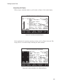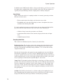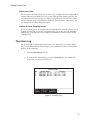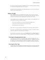
1
The In-Line Manifold
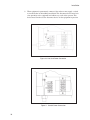
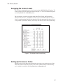
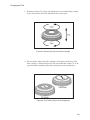
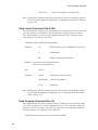
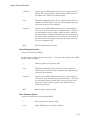
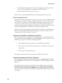
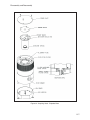
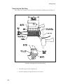
3. Use the bar clamp to hold the metal Air Intake Seal Ring in place as you
remove the screws (refer to Figure 85).
CAUTION Failure to use the clamp while removing screws can result in
elongation of the slots in the plastic In-Line Manifold. This, in
turn, can result in a poor vacuum seal when the unit is reassembled.
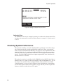
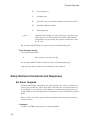
4. Start at one end of the split in the metal Air Intake Seal Ring (moving the clamp
as you go along) and remove all of the screws one by one.
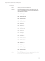
5. Remove the bar clamp, then remove the sampling head top cover.
6. Turn the In-Line Manifold until the intake pipe is pointing in the desired
direction.
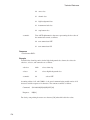
7. Reassemble the AS010 In-Line Manifold starting with Step 7 on page 229.
Installing the AS010 In-Line Manifold
This procedure is to be used for field installation of the AS010 In-Line Manifold. It also
covers removal and realignment of the AS010 In-Line Manifold on a sampling head.
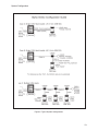
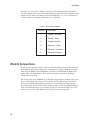
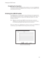
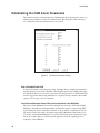
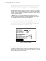
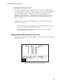
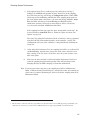
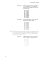
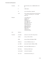
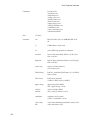
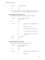
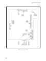
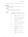
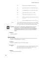
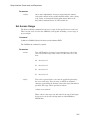
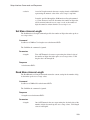
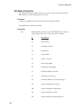
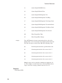
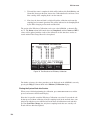
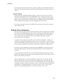
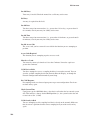
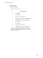
Check your field installation kit to be sure you have all of the necessary parts. Use Figures 85, 86, and 87, to help identify the parts.
Quantity
Description
1
In-Line Manifold
1
1/8 by 7 in. diameter (3 mm by 17.75 cm) (I.D.) O-Ring (may be
mounted in Manifold)
1
3/16 by 6.9 in. diameter (5 mm by 17.5 cm) (I.D.) O-Ring
1 1 in. (2.5 cm) diameter O-Ring (may already be mounted in the Manifold’s intake
pipe)
1
Spacer
1
6 in. (15 cm) Adapter Pipe
1
Metal Air Intake Seal Ring
227