1
Field Installing the Alarm Option
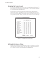
Field Installing the Alarm Option
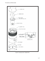
The Model AS020 Alarm Option, which mounts on top of the sampling head, provides
an audible and visual alarm for the sampling head.
The AS020 is provided as a fully assembled unit. Before installing it on the sampling
head, the cover plates must be removed from both the sampling head and the AS020.
1. Put the sampling head off-line and disconnect its power.
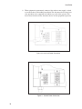
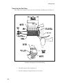
2. Remove the three pan-head screws which secure the AS020’s flat cover and
remove the cover.
3. Remove the three countersunk Phillips-head screws which secure the sampling
head’s cover.
4. Remove the Head’s cover; it will not be used.
5. Locate the alarm wire harness and 8-pin connector in the Head.
6. Slide this connector through the opening in the AS020’s cover.
7. Press the connector firmly into its mate on the printed circuit board in the
AS020’s housing. Note that the connector is keyed for proper orientation.
8. Reattach the AS020’s flat cover to the AS020’s housing, using its three
pan-head screws.
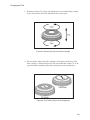
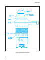
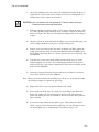
9. If your unit has the AS010 In-Line Manifold option, put its circular plastic
spacer inside the top of the Manifold
10. Mount the AS020 on the top of the sampling head, using the three Phillips-head
screws which held the sampling head’s original cover in place.
CAUTION Use a maximum of 6 inch-pounds (0.7 newton meter) of torque.
Excessive force can crack the plastic.
Checking for Proper Operation
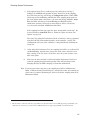
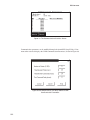
Turn on the sampling head’s power. Depending on how the sampling head Annunciators
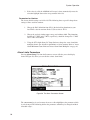
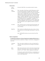
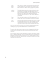
were configured, the audible and/or visual alarms may be activated. To verify proper operation, use the ASM1000’s Diagnostic Menu to activate the sampling head’s:
• Lamp Check
223