1
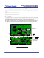
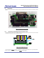
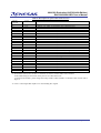
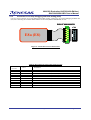
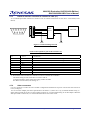
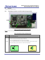
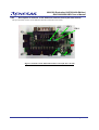
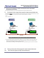
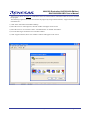
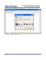
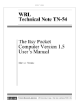
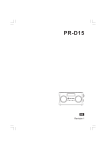
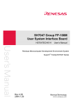
User’s Manual
PLC Micro-controller,M16C/6S
Evaluation Kit
EV5 (ASIA Edition) User’s Manual
Renesas single chip microcomputer
M16C family /M16C/6S group
Rev.1.2 2009.05
M16C/6S Evaluation Kit EV5(ASIA Edition)
-R0K3306S0D011BR- User’s Manual
Contents
1.
Precautions for Safety....................................................................................................................... 3
2.
Introduction ....................................................................................................................................... 5
3.
Special Cautions ............................................................................................................................... 5
4. Product Overview.............................................................................................................................. 5
4.1 Features of the product..................................................................................................................... 5
4.2 Product structure............................................................................................................................... 6
4.3 Product specification......................................................................................................................... 7
4.4 Limited uses ...................................................................................................................................... 7
4.5 How to get the M16C/6S data link layer library (provided free) ........................................................ 8
4.6 Structure............................................................................................................................................ 8
4.7 Connectors........................................................................................................................................ 9
4.7.1 Connector for connecting to external systems (CN4) ................................................................ 9
4.7.2 Connector for on-chip debugging and flash writing (CN2) ....................................................... 11
4.7.3 RS232-C interface connector to connect to a PC (J1) ............................................................. 12
4.7.4 Other connectors ...................................................................................................................... 12
4.8 Switches.......................................................................................................................................... 13
4.8.1 Description of switches on the PLC module (the upper board)................................................ 13
4.8.2 Description of switches on the dedicated interface board (the lower board) ........................... 14
4.9 LED ................................................................................................................................................. 16
4.10 AC Cables ....................................................................................................................................... 16
5. How to use the program for simple communication tests and software development environment17
5.1 Environment for the usage of the program for simple communication tests. ................................. 17
5.2 Start-up and execution of the program for simple communication tests......................................... 17
5.2.1 How to start the program for simple communication tests ....................................................... 17
5.2.2 Setting procedure for the receiver ............................................................................................ 22
5.2.3 Setting procedure for the sender .............................................................................................. 24
5.2.4 Transmission modes (Unicast and Broadcast)......................................................................... 25
5.3 Sample Test Program’s ID Code .................................................................................................... 26
5.4 Software Developing Environment ................................................................................................. 26
REJ10Z0002-0101/Rev.1.2
May 2009
Page 2 of 28
M16C/6S Evaluation Kit EV5(ASIA Edition)
-R0K3306S0D011BR- User’s Manual
1.
Precautions for Safety
Definitions of Signal Words
In both the user’s manual and on the product itself, several icons are used to insure proper handling of this product and
also to prevent injuries to you or other persons, or damage to your properties.
This chapter describes the precautions which should be taken in order to use this product safely and properly. Be sure to
read this chapter before using this product.
This symbol represents a warning about safety. It is used to arouse caution about a potential
danger that will possibly inflict an injury on persons. To avoid a possible injury or death,
please be sure to observe the safety message that follows this symbol.
WARNING
WARNING indicates a potentially dangerous situation that will cause death or heavy wound
unless it is avoided.
CAUTION
CAUTION indicates a potentially dangerous situation that will cause a slight injury or a
medium-degree injury unless it is avoided.
In addition to the three above, the following are also used as appropriate.
means WARNING or CAUTION.
Example:
CAUTION AGAINST AN ELECTRIC SHOCK
means PROHIBITION.
Example:
DISASSEMBLY PROHIBITED
means A FORCIBLE ACTION.
Example:
UNPLUG THE POWER CABLE FROM THE RECEPTACLE
REJ10Z0002-0101/Rev.1.2
May 2009
Page 3 of 28
M16C/6S Evaluation Kit EV5(ASIA Edition)
-R0K3306S0D011BR- User’s Manual
WARNING
Warnings for AC Power Supply:
z Do not touch the plug of the AC power cable when your hands are wet. This may cause electric shock.
z If other equipment is connected to the same branch circuit, care should be taken not to overload the
circuit.
z If you smell a strange odor, hear an unusual sound, or see smoke coming from this product, then
disconnect power immediately by unplugging both the AC/DC Adapter and the AC power cable for PLC
signal from the outlet.
Do not use this as it is because of the danger of electric shock and/or fire. In this case, contact your local
distributor.
z Before setting up this emulator and connecting it to other devices, turn off power or remove a power
cable to prevent injury or product damage.
Warnings to Be Taken for This Product:
z Do not disassemble or modify this product. Personal injury due to electric shock may occur if this
product is disassembled and modified. Disassembling and modifying the product will void your
warranty.
z Make sure nothing falls into the cooling fan on the top panel, especially liquids, metal objects, or
anything combustible.
Warning for Installation:
z Do not set this product in water or areas of high humidity. Make sure that the product does not get wet.
Spilling water or some other liquid into the product may cause unrepairable damage.
Warning for Use Environment:
z This equipment is to be used in an environment with a maximum ambient temperature of 40°C. Care
should be taken that this temperature is not exceeded.
REJ10Z0002-0101/Rev.1.2
May 2009
Page 4 of 28
M16C/6S Evaluation Kit EV5(ASIA Edition)
-R0K3306S0D011BR- User’s Manual
2.
Introduction
Thank you for purchasing our PLC micro-controller evaluation kit, EV5.
EV5 is designed to for Renesas Technology’s PLC micro-controller M16C/6S and works for PLC communication
within the FCC band. Also, EV5 has a built-in program*1 for simple communication test written in a flash memory,
so that it is possible to evaluate performance immediately in PLC communication of M16C/6S. Besides, RS232C
interface is also included, allowing easy connection to a PC. The following part explains the product overview and
usage of EV5.
3.
Special Cautions
1) PLC Regulations
Please confirm with PLC regulations in your use region and execute the necessary procedures before it used.
2) ACDC Adapter
We include other company’s AC/DC power supply in this kit for the convenience.
AC/DC power supply is not our product, SO WE CAN NOT GUARANTEE ALL THINGS INCLUDING
SAFETY ISSUES, RELATED WITH THE AC/DC POWER SUPPLY.
Please be careful for safety when it works.
And please use it for only developing and testing after confirming the safety standard regulation in utilization
area.
Please do not resell to the consumer, and let it use.
Do not touch the plug of AC power cable when your hands are wet. This may cause electric shock.
4.
Product Overview
4.1
Features of the product
Features of EV5 are summarized in the following Table 1.
Table 1: Features of EV5
Features
Advantages
1.Equipped with RS232C interface
Easily connectable to a PC.
2.Built-in program for simple communication tests
Allows simple communication tests without
developing software.
3.Equipped with a connector for on-chip debugger
Connectable to Renesas’ debugger or flash writer
4.Equipped with connectors which are accessible to
Enables to develop various applications
all free I/O ports of M16C/6S micro-controller
5.Equipped with a selector for power switching
Allows power supply both from AC/DC adapter
(DC5V) and customer’s application systems.
*1: The simple communication test program is same with the sample program included in D2DL (DLL library ).
REJ10Z0002-0101/Rev.1.2
May 2009
Page 5 of 28
M16C/6S Evaluation Kit EV5(ASIA Edition)
-R0K3306S0D011BR- User’s Manual
4.2
Product structure
The following Table 2 and Figure1 show contents of EV5.
Table 2: Contents of EV5
Product Name
Description
Qt.
1.The evaluation kit body
Consists of a PLC module and a dedicated interface board
1
2.AC/DC adapter
DC5V 2A
1
3.Cable to connect to a PC
Serial crossing cable
1
4.E8a/E8 14PIN-10PIN Convert Board
14-10 convert board for E8a/E8 (R0KZC000000002R)
1
5.AC cable for 125VAC
For outputting PLC signals (Withstand voltage:125V)
1
6.AC cable for 250VAC
For outputting PLC signals (Withstand voltage 250V)
1
1. The evaluation kit body
2. AC/DC adapter
3 .Cable to connect to a PC
4. 14-10 convert board for E8a/E8
5. AC cable for 125VAC
6 AC cable for 250VAC
Figure 1: Contents of EV5
REJ10Z0002-0101/Rev.1.2
May 2009
Page 6 of 28
M16C/6S Evaluation Kit EV5(ASIA Edition)
-R0K3306S0D011BR- User’s Manual
4.3
Product specification
The specification of EV5 is described in the following Table 3
Table 3: Specification of EV5
Items
Description
Communication
Select among the following three modes*2
Speed
Standard Mode (SM)
7.5Kbps
Robust Mode (RM)
5.0Kbps
Extremely Robust Mode (ERM)
1.25Kbps
Voltage for PLC
communication
Under 125VAC, when AC cable for 125VAC is connected with evaluation kit body.
Operating supply voltage
DC 5V
Size
70mm(W)*47mm(L)*47mm(H)
Connectors for external
connection
4 connectors:
Under 240VAC, when AC cable for 240VAC is connected with evaluation kit body.
1. Connector for PLC signals (2 pins)
2. Connector for connecting to external systems (26 pins)
3. Connector for connecting to a PC - SUB connector (9 pins)
4. Connector for on-chip debugging and flash memory writing (10pins)
Switches
3 switches:
1. Reset switch (SW1 on the upper board)
2. Reset switch (SW1 on the lower board)
3. Switch for switching CNVss modes (SW2 on the upper board)
Operating Ambient
15 to 40 degrees
Temperature
Power consumption
In transmission: approx. 700mW (Transmission load 51Ω)
In reception: approx.450mW
Included Sample Program
Program for simple communication tests
(This program and the sample program included in DLL library D2DL are the same.)
*2: When it uses the “adaptive rate control” function, the transmission speed is automatically switched to
SM→RM→ERM depending on the status of the transmission channel.
4.4
Limited uses
Since EV5 is developed to evaluate LSI without considering operating ambient temperature and humidity, please
avoid embedding this product to your devices to sell.
REJ10Z0002-0101/Rev.1.2
May 2009
Page 7 of 28
M16C/6S Evaluation Kit EV5(ASIA Edition)
-R0K3306S0D011BR- User’s Manual
4.5
How to get the M16C/6S data link layer library (provided free)
In order to develop an application program by using this board, you will need our data link layer library provided free.
Various sample programs and documents which may be useful in developing application programs have also been
prepared. If you would like some of them, please contact our contact center ([email protected]), using the following
subject.
Subject: Request M16C/6S data link layer library
We will send a "user registration form" by return.
4.6
Structure
EV5 consists of two boards. The upper board is a PLC modem module which is comprised of a PLC microcomputer
and its peripheral circuit. The lower board is a dedicated interface board which has four connectors, the connector for
on-chip debugging and flash memory writing (CN2), the RS232-C connector to connect to the PC (J1), the connector
for connecting to external systems (CN4), and the connector for connecting to the upper board (CN3).
The connector CN4 and the connector U-CN1 on the upper board have the same pin configuration and number of
pins. Therefore it is also possible to connect the PLC module directly to your system without using the interface
board (the lower board).
Sending
U1
Regulator
Receiving
3.3V
U4
Line Driver
U2
M16C/6S
Receiving
Circuits
U3
EEPROM
22
U-SW2
PLC Module
(Upper Board)
Coupling
Circuits
3.3V
2
U-SW1
AC Line
U-CN1
5V
UCN2
AC Line
J1
SW1
5V
SW4
SW3
TS
P62
CN2
CN3
P63
5V
I/F Module for PC and
Flash programmer
(Lower Board)
RS232C
Driver
P81
TS
SW5
SW2
CN4
Figure 2: EV5 circuit block diagram
REJ10Z0002-0101/Rev.1.2
May 2009
Page 8 of 28
M16C/6S Evaluation Kit EV5(ASIA Edition)
-R0K3306S0D011BR- User’s Manual
4.7
Connectors
This part explains details about the connectors on the I/F module (the lower board) which are connected to external
systems.
CN3
J1
CN1
CN2
CN4
Figure 3: Connectors on the I/F board
4.7.1
Connector for connecting to external systems (CN4)
CN4 is a connector to connect EV5 to external systems. CN4 connects to free I/O pins on M16C/6S microcomputer.
Configuration and functions of pins on CN4 are as follows.
CN4
25
1
26
2
Figure 4: Pin configuration of CN4
As described above in Figure 4, CN4 has a configuration on which the upper right pin is the 1st pin and the bottom
left one is the 26th. For details about each pin, see Table 4 on the next page.
REJ10Z0002-0101/Rev.1.2
May 2009
Page 9 of 28
M16C/6S Evaluation Kit EV5(ASIA Edition)
-R0K3306S0D011BR- User’s Manual
Table 4: Description for pins of the connector CN4
Pin No.
on CN4
1
2
3
4
5
6
7
8
9
10
11
12
13
14
15
16
17
18
19
20
21
22
23
24
25
26
I or O
Destination
5V
3.3V
GND
I/O
I/O
I/O
I/O
I
I/O
RESET
I/O
I/O
I/O
I/O
I/O
I/O
I/O
I/O
O
I/O
I/O
I/O
I/O
I/O
I/O
GND
Inputs DC5V
Outputs 3.3V which is generated by the evaluation board
Connects to M16C/6S Pin 25 (P64/CTS1/RTS1/CLKS1)
Connects to M16C/6S Pin 21 (P65/CLK1)
Connects to M16C/6S Pin 27 (P66/RXD1/SCL1)
Connects to M16C/6S Pin 15 (P15/INT3)
Connects to M16C/6S Pin 49 (CNVSS)
Connects to M16C/6S Pin 23 (P67/TXD1/SDA1)
Connects to M16C/6S Pin 20 (RESET)
Connects to M16C/6S Pin 22 (P92/SOUT3)
Connects to M16C/6S Pin 30 (P61/CLK0)
Connects to M16C/6S Pin 28 (P60/CTS0/RTS0)
Connects to M16C/6S Pin 24 (P91/SIN3)
Connects to M16C/6S Pin 26 (P90/CLK3)
Connects to M16C/6S Pin 32 (P63/TXD0/SD0)*3
Connects to M16C/6S Pin 33 (P62/RXD0/SCL0)*3
Connects to M16C/6S Pin 29 (P73/CTS2/RTS2/TA1IN)
Connects to M16C/6S Pin 31 (TS)*4
Connects to M16C/6S Pin 16 (P80/TA4OUT)
Connects to M16C/6S Pin 34 (P83/INT1)
Connects to M16C/6S Pin 35 (P74/TA2OUT)
Connects to M16C/6S Pin 36 (P81/TA4IN) *3
Connects to M16C/6S Pin 37 (P76/TA3OUT)
Connects to M16C/6S Pin 38 (P84/INT2)
*3: Destinations of P62, P63, and P81 are switched via selector switches SW3, SW4, and SW5.
In the initial setting of each switch, these pins are not connected to CN4.
To use P62, P63 and P81, please change the setting of SW3, SW4, and SW5. For details of each switch, refer to
Page.13.
*4: TS is a control signal that outputs 3.3V when sending PLC signals.
REJ10Z0002-0101/Rev.1.2
May 2009
Page 10 of 28
M16C/6S Evaluation Kit EV5(ASIA Edition)
-R0K3306S0D011BR- User’s Manual
4.7.2
Connector for on-chip debugging and flash writing (CN2)
CN2 is a 10-pin connector for on-chip debugging and flash writing. Connect it to an on-chip debugging emulator E8a
(E8) after connecting the included 14PIN-10PIN convert board (R0KZC000000002R) to CN2.
R0KZC000000002R
CN2
10
E8a (E8)
2
Figure 5: Connection between E8 and EV5
Table 5: Description for pins of the connector CN2
Pin No.
on CN2
1
2
3
4
5
6
7
8
9
10
I or O
Destination
3.3V
I/O
I/O
I/O
I/O
N.C
GND
RESET
I
I/O
Connects to 3.3V
Connects to M16C/6S Pin 25 (P64/CTS1/RTS1/CLKS1)
Connects to M16C/6S Pin 21 (P65/CLK1)
Connects to M16C/6S Pin 27 (P66/RXD1/SCL1)
Connects to M16C/6S Pin 15 (P15/INT3)
REJ10Z0002-0101/Rev.1.2
Connects to M16C/6S Pin 20 (RESET)
Connects to M16C/6S Pin 49 (CNVSS)
Connects to M16C/6S Pin 23 (P67/TXD1/SDA1)
May 2009
Page 11 of 28
M16C/6S Evaluation Kit EV5(ASIA Edition)
-R0K3306S0D011BR- User’s Manual
4.7.3
RS232-C interface connector to connect to a PC (J1)
J1 is a DSUB9-pin female connector to connect to a PC. It connects to M16C/6S via 232 driver on I/F board (Lower
Board).
1
2
6
3
7
4
8
2
3
5
7
8
5
9
232C
M16C/6S
Driver
MAX3223CAP
GND
GND
Figure 6: Connection diagram of J1
Table 6: Description for pins of the connector J1
Pin No. on
J1
1
2
3
4
5
6
7
8
9
I or O
N.C
I/O
I/O
N.C
GND
N.C
GND
N.C
N.C
Destination
Connects to M16C/6S Pin 33 (P62/RXD0/SCL0)*5
Connects to M16C/6S Pin 32 (P63/TXD0/SDA0)*5
*5: Destinations of P62 and P63 are switched via selector switches SW3 and SW4.
The initial setting of each switch does not connect with J1.
To use P62 and P63, please change the setting of SW3 and SW4.
For details of each switch, refer to Page.13.
4.7.4
Other connectors
CN3 is a connector to connect to a PLC module. Configuration and functions of pins on CN3 are the same as those of
CN4. (see Page 8).
CN1 is an AC/DC adapter jack whose specification is as follows: (1) Inner core 1.7ϕ, (2) Outside diameter 4.0ϕ, (3)
Input voltage-current DC5V/2A. It is also possible to supply 5V via CN4 without using an AC/DC adapter. When the
short pin of SW1 is taken out, CN1 is disconnected from 5V line on the circuit.
REJ10Z0002-0101/Rev.1.2
May 2009
Page 12 of 28
M16C/6S Evaluation Kit EV5(ASIA Edition)
-R0K3306S0D011BR- User’s Manual
4.8
Switches
This part explains switches of EV5.
4.8.1
Description of switches on the PLC module (the upper board)
U-SW2
U-SW1
Figure 7: Location of switches on the upper board
Figure 7 is a picture of the upper board which has two switches, U-SW1 and U-SW2.
Table 7: Description of switches on the upper board
Number
U-SW1
Functions
Reset Switch for M16C/6S
This switch is used only when M3A-0806 (TEN_NINE) shall be connected.
U-SW2 is connected to CNVSS pin (49 pin) of M16C/6S
In case of usingE8a (E8), please fix U-SW2 as below left figure.
U-SW2
In case of using M3A-0806, please set U-SW2 as below right figure during writing a program.
Only when writing a program, please set U-SW2 as below right figure
1
1
3
3
Not writing program
REJ10Z0002-0101/Rev.1.2
Writing program
May 2009
Page 13 of 28
M16C/6S Evaluation Kit EV5(ASIA Edition)
-R0K3306S0D011BR- User’s Manual
4.8.2
Description of switches on the dedicated interface board (the lower board)
This part describes switches on the dedicated interface board (the lower board).
SW3
SW5
SW1
SW4
SW2
Figure 8: Switches on the dedicated interface board (the lower board)
REJ10Z0002-0101/Rev.1.2
May 2009
Page 14 of 28
M16C/6S Evaluation Kit EV5(ASIA Edition)
-R0K3306S0D011BR- User’s Manual
Table 8: Description of switches on the dedicated interface board (the lower board)
Number
SW1
Functions
Selector plug switch for DC 5V power supply.
In case that SW1 is on, please input DC5V via SW1.
In case that SW1 is off, please input DC5V via the 1st pin of CN4
SW2
Reset Switch for M16C/6S (Same as U-SW1)
SW3
Selector plug switch for P63
: On the initial condition, P63 is connected to Pin3 of CN2 via 232C driver.
P63 is connected to Pin16 of CN4
SW4
Selector plug switch for P62
On the initial condition, P62 is connected to Pin2 of CN2 via 232C driver
P62 is connected to Pin17 of CN4
SW5
Selector plug switch for P81
On the initial condition, P81 is connected to circuits for green LED
P81 is connected to Pin23 of CN4
REJ10Z0002-0101/Rev.1.2
May 2009
Page 15 of 28
M16C/6S Evaluation Kit EV5(ASIA Edition)
-R0K3306S0D011BR- User’s Manual
4.9
LED
EV5 has two LEDs to show the communication status of PLC.
Table 9: Description of LEDs
Explanation
RED
Blink on and off when PLC module is sending PLC signal.
RED LED’s circuit is connected with “TS” control signal (Pin31 of M16C/6S)
TS control signal outputs 3.3V during M16C/S sends PLC signal.
GREEN *6
When the setting is in the initial condition, GREEN LED’s circuit is connected with P81
In the case of sample program, GREEN LED blinks on and off when M16C/6S received PLC
signal.
*6: There may be rare occasions when not PLC data but noise makes the LED blink on and off .
4.10
AC Cables
EV5 has two AC cables. One is for under 125VAC with “A” type plug and the other is for under 250VAC with “F”
type plug. Please select the cable after confirming the voltage in the use region.
Figure 9: Cable for 125VAC
REJ10Z0002-0101/Rev.1.2
Figure 10: Cable for 250VAC
May 2009
Page 16 of 28
M16C/6S Evaluation Kit EV5(ASIA Edition)
-R0K3306S0D011BR- User’s Manual
5.
How to use the program for simple communication tests and software
development environment
The following part explains how to use the included program for simple communication tests.
5.1
Environment for the usage of the program for simple communication tests.
The following Figure 11 shows the environment for the usage of the program for simple communication tests. In case
of using the program for PLC communication evaluation, the following items are required.
1. EV5:
2
2. PC to control EV5: 2
Sender PLC
Receiver PLC
Control PC
Control PC
Serial cable (Cross)
Serial cable (Cross)
*7
*7
AC/DC ADAPTER
AC/DC ADAPTER
EV5 Body
R0K3306S0D011BR
EV5
R0K3306S0D011BR
Body
Power Line
Figure 11: Environment for the usage of the program for simple communication tests
*7: In an environment where the communication condition is very severe, influence of the AC/DC adapters may
affect the communication performance. In order to decrease the impact caused by AC/DC adapters, please
connect the AC/DC adapters to other than outlet of PLC line.
In case that the AC/DC adapters can be suspected as a cause of a phenomenon, please try the above measures.
5.2
5.2.1
Start-up and execution of the program for simple communication tests
How to start the program for simple communication tests
REJ10Z0002-0101/Rev.1.2
May 2009
Page 17 of 28
M16C/6S Evaluation Kit EV5(ASIA Edition)
-R0K3306S0D011BR- User’s Manual
After set up as shown in Figure 11, establish the status of terminal software of both the sender and receiver and start
the program.
The following explains how to start and execute the program by using terminal software, “Hyper Terminal” installed
in Windows PC.
1) Click “Start” left bottom of Windows desktop
2) Move the cursor to “All Programs”, then sub window will appear on the screen.
3) Move the cursor to “Accessories” and to “Communications” on another sub window.
4) You can find “Hyper Terminal” icon on another window.
5) Click “Hyper terminal”, then a new window as follows will appear on the screen.
REJ10Z0002-0101/Rev.1.2
May 2009
Page 18 of 28
M16C/6S Evaluation Kit EV5(ASIA Edition)
-R0K3306S0D011BR- User’s Manual
Enter an arbitrary name and choose an icon, then click “OK”.
Another sub window as shown below will appear.
REJ10Z0002-0101/Rev.1.2
May 2009
Page 19 of 28
M16C/6S Evaluation Kit EV5(ASIA Edition)
-R0K3306S0D011BR- User’s Manual
Select COM port
to which the serial
cable is connected
After checking that the COM port to which the serial cable is connected is selected as “Connect using”, click “OK”.
Then the sub window as shown below will appear. Set each COM port condition as follows and click “OK”.
REJ10Z0002-0101/Rev.1.2
May 2009
Page 20 of 28
M16C/6S Evaluation Kit EV5(ASIA Edition)
-R0K3306S0D011BR- User’s Manual
The COM setting window will be cleared, and only the terminal window will remain on the desktop. After that, push
the reset switch of EV5 once. The program for simple communication tests will be started, and the following
messages shown on the next page will appear on the terminal window.
REJ10Z0002-0101/Rev.1.2
May 2009
Page 21 of 28
M16C/6S Evaluation Kit EV5(ASIA Edition)
-R0K3306S0D011BR- User’s Manual
------- D2DLL Test Program (V1.00) ------Copyright Renesas Technology Corporation and
Renesas Solutions Corporation
<< note >> Use Number key & Back space.
Enter Network ID (1-1023) >
This will complete the start-up of the program for simple communication tests.
5.2.2
Setting procedure for the receiver
In case of using communication software, it is necessary to set a fixed ID to each node. Therefore different IDs
should be set to the sender modem and the receiver modem respectively.
Set the receiver modem first. When the sample program is started, the following message will appear.
Enter Network ID (1-1023) >
Input an arbitrary number and press the return key. (The number input here is to be the network ID number.)
The following message appears now.
Enter Source Node ID (1-2047) >
Input an arbitrary number and press the return key again. (The number input here is to be the ID number of the sender
PLC modem.) The following message appears next.
Enter Destination Node ID (1-2047) >
Input an arbitrary number which is different from the above, and press the return key. (The number input here is to be
the ID number of the receiver PLC modem.)
When the procedure has been completed, dedicated middleware D2DL for PLC communication would be initialized.
After the initialization, the display on the terminal will change as follows.
REJ10Z0002-0101/Rev.1.2
May 2009
Page 22 of 28
M16C/6S Evaluation Kit EV5(ASIA Edition)
-R0K3306S0D011BR- User’s Manual
------- D2DLL Test Program (V1.00) ------Copyright Renesas Technology Corporation and
Renesas Solutions Corporation
<< note >> Use Number key & Back space.
Enter Network ID (1-1023) > 1
Enter Source Node ID (1-2047) > 1
Enter Destination Node ID (1-2047) > 2
D2DL Initialize..... Successful.
******** PLC TEST MENU ********
1. Transmit 100packets by UniCast (40byte)
2. Transmit 100packets by BroadCast (40byte)
3. Transmit 500packets by UniCast (40byte)
4. Transmit 500packets by BroadCast (40byte)
5. Count Received Packets
Select 5 among the PLC TEST MENU and press the return key.
EV5 will change into a standby state for reception. Once the return key is pressed again, the number of packets received
from an arbitrary node.
This will complete the setting procedure for the receiver.
REJ10Z0002-0101/Rev.1.2
May 2009
Page 23 of 28
M16C/6S Evaluation Kit EV5(ASIA Edition)
-R0K3306S0D011BR- User’s Manual
5.2.3
Setting procedure for the sender
In the setting for the sender, enter the same network ID as the receiver’s, and set the opposite numbers to Source ID
and Destination ID from those of the receiver.
------- D2DLL Test Program (V1.00) ------Copyright Renesas Technology Corporation and
Renesas Solutions Corporation
<< note >> Use Number key & Back space.
Enter Network ID (1-1023) > 1
Enter Source Node ID (1-2047) > 2
Enter Destination Node ID (1-2047) >1
D2DL Initialize..... Successful.
******** PLC TEST MENU ********
1. Transmit 100packets by UniCast (40byte)
2. Transmit 100packets by BroadCast (40byte)
3. Transmit 500packets by UniCast (40byte)
4. Transmit 500packets by BroadCast (40byte)
After setting IDs, select a transmit mode from 1 to 4. Press the return key, and the transmission starts.
When the transmission has been completed, a message showing the completion will appear on the above window.
Once this message appears, the number of the received packets can be checked by pressing the return key on the
receiver PC.
This is a sequence of the sample program.
REJ10Z0002-0101/Rev.1.2
May 2009
Page 24 of 28
M16C/6S Evaluation Kit EV5(ASIA Edition)
-R0K3306S0D011BR- User’s Manual
5.2.4
Transmission modes (Unicast and Broadcast)
The below Table 10 summarizes the difference between unicast and broadcast. Note that the transmit mode and the
re-transmit times in the table depend on the program development, so that they can be changed.
Unicast communication is a 1-to-1 communication method in which data is sent to a specified node to communicate
with. The data (No. x th) receiver node returns an acknowledge to the data sender node. When the sender receives the
acknowledge, it sends the next data (No. x+1 th). If it cannot receive the acknowledge within a defined period, it will
send the same data (No. x th) again. Re-transmit times are twice. After sending twice, the sender will send the next
data (No. x+1 th) regardless of the acknowledge.
In unicast communication, “adaptive rate control”(ARC) function is adopted, in which the transmission mode is
automatically switched depending on the status of the transmission channel. At first, ARC transmits data in SM mode
of 7.5Kbps. And, if the acknowledge from the receiver does not come back, ARC shifts the transmit mode
automatically to RM mode of 5.0Kbps. In addition, when the acknowledge cannot be received even in RM mode,
ARC shifts the mode to ERM mode of 1.25Kbps. Moreover, when the acknowledge can be continuously received
twice or more times in ERM mode, it is judged that the status of the transmission channel has recovered, and the
mode returns to RM mode. In a similar way, when the acknowledge can be continuously received twice or more
times in RM mode, the mode returns to SM mode.
Broadcast communication is a 1-to-many communication method in which data can be sent to all nodes at a time in
the network without specifying a node to communicate with. The data receiver nodes do not send back the
acknowledge in spite of the data reception. Therefore adaptive rate control function is not supported in broadcast
communication. The data transmit mode is fixed to RM mode of 5.0Kbps, and re-transmission is not performed.
Table 10: Difference between Unicast and Broad cast
Unicast
Communication method
Transmit mode*8
Acknowledge
1 to 1
Adaptive rate control
Broadcast
one to many
RM mode fixed
Yes
No
Re-transmit times*8
Twice
0
Menu num ber
1 and 3
from Receiver
2 and 4
*8:They depend on the application program development , so that they can be changed.
For more details, please contact [email protected] which is introduced in 4.5.
REJ10Z0002-0101/Rev.1.2
May 2009
Page 25 of 28
M16C/6S Evaluation Kit EV5(ASIA Edition)
-R0K3306S0D011BR- User’s Manual
5.3
Sample Test Program’s ID Code
EV5 is shipped with sample test program written in the flash memory of M16C/6S.
The ID code for protecting it written in flash memory is “00000000000000”(all zeros).
Please input all zeros on the input screen as shown in the figure below, when you debug or write your program to the
flash memory of M16C/6S using E8a/E8.
5.4
Software Developing Environment
Environment to develop a PLC communication application using EV5 is as follow.
1. Integrated Development Environment (IDE) High-performance Embedded Workshop*9*10
2. C compiler
M3T-NC30WA Ver5.40
3. On-chip Emulator
E8a/E8
4. Debugger GUI (Integrated in 1)
E8a/E8 Emulator software*9
9
5. Flash program software FDT*
6. E8a/E8 14PIN-10PIN Convert Board R0KZC000000002R (Included in this product)
7. Data Link Layer Library D2DL*11
*9 It is included in C compiler package software.
*10 It can be free downloaded from RENESAS Web Site.
*11 Renesas offers free D2DL individually. Please contact [email protected]
For more details about D2DL, please access the URL as follows.
http://japan.renesas.com/fmwk.jsp?cnt=m16c6s_root.jsp&fp=/products/mpumcu/plc_mpumcu/m16c60_plc_series/m
16c6s_group/
All trademarks and registered trademarks are the property of their respective owners.
WINDOWS is the trademark and property of Microsoft Corporation in the United States.
REJ10Z0002-0101/Rev.1.2
May 2009
Page 26 of 28
M16C/6S Evaluation Kit EV5(ASIA Edition)
-R0K3306S0D011BR- User’s Manual
Notes regarding these materials
1.
2.
3.
4.
5.
6.
7.
8.
9.
10.
11.
12.
13.
This document is provided for reference purposes only so that Renesas customers may select the appropriate
Renesas products for their use. Renesas neither makes warranties or representations with respect to the
accuracy or completeness of the information contained in this document nor grants any license to any intellectual
property rights or any other rights of Renesas or any third party with respect to the information in this document.
Renesas shall have no liability for damages or infringement of any intellectual property or other rights arising out
of the use of any information in this document, including, but not limited to, product data, diagrams, charts,
programs, algorithms, and application circuit examples.
You should not use the products or the technology described in this document for the purpose of military
applications such as the development of weapons of mass destruction or for the purpose of any other military
use. When exporting the products or technology described herein, you should follow the applicable export
control laws and regulations, and procedures required by such laws and regulations.
All information included in this document such as product data, diagrams, charts, programs, algorithms, and
application circuit examples, is current as of the date this document is issued. Such information, however, is
subject to change without any prior notice. Before purchasing or using any Renesas products listed in this
document, please confirm the latest product information with a Renesas sales office. Also, please pay regular
and careful attention to additional and different information to be disclosed by Renesas such as that disclosed
through our website. (http://www.renesas.com)
Renesas has used reasonable care in compiling the information included in this document, but Renesas
assumes no liability whatsoever for any damages incurred as a result of errors or omissions in the information
included in this document.
When using or otherwise relying on the information in this document, you should evaluate the information in light
of the total system before deciding about the applicability of such information to the intended application.
Renesas makes no representations, warranties or guaranties regarding the suitability of its products for any
particular application and specifically disclaims any liability arising out of the application and use of the
information in this document or Renesas products.
With the exception of products specified by Renesas as suitable for automobile applications, Renesas products
are not designed, manufactured or tested for applications or otherwise in systems the failure or malfunction of
which may cause a direct threat to human life or create a risk of human injury or which require especially high
quality and reliability such as safety systems, or equipment or systems for transportation and traffic, healthcare,
combustion control, aerospace and aeronautics, nuclear power, or undersea communication transmission. If you
are considering the use of our products for such purposes, please contact a Renesas sales office beforehand.
Renesas shall have no liability for damages arising out of the uses set forth above.
Notwithstanding the preceding paragraph, you should not use Renesas products for the purposes listed below:
(1) artificial life support devices or systems
(2) surgical implantations
(3) healthcare intervention (e.g., excision, administration of medication, etc.)
(4) any other purposes that pose a direct threat to human life
Renesas shall have no liability for damages arising out of the uses set forth in the above and purchasers who
elect to use Renesas products in any of the foregoing applications shall indemnify and hold harmless Renesas
Technology Corp., its affiliated companies and their officers, directors, and employees against any and all
damages arising out of such applications.
You should use the products described herein within the range specified by Renesas, especially with respect to
the maximum rating, operating supply voltage range, movement power voltage range, heat radiation
characteristics, installation and other product characteristics. Renesas shall have no liability for malfunctions or
damages arising out of the use of Renesas products beyond such specified ranges.
Although Renesas endeavors to improve the quality and reliability of its products, IC products have specific
characteristics such as the occurrence of failure at a certain rate and malfunctions under certain use conditions.
Please be sure to implement safety measures to guard against the possibility of physical injury, and injury or
damage caused by fire in the event of the failure of a Renesas product, such as safety design for hardware and
software including but not limited to redundancy, fire control and malfunction prevention, appropriate treatment
for aging degradation or any other applicable measures. Among others, since the evaluation of microcomputer
software alone is very difficult, please evaluate the safety of the final products or system manufactured by you.
In case Renesas products listed in this document are detached from the products to which the Renesas products
are attached or affixed, the risk of accident such as swallowing by infants and small children is very high. You
should implement safety measures so that Renesas products may not be easily detached from your products.
Renesas shall have no liability for damages arising out of such detachment.
This document may not be reproduced or duplicated, in any form, in whole or in part, without prior written
approval from Renesas.
Please contact a Renesas sales office if you have any questions regarding the information contained in this
document, Renesas semiconductor products, or if you have any other inquiries.
REJ10Z0002-0101/Rev.1.2
May 2009
Page 27 of 28
M16C/6S Evaluation Kit EV5(ASIA Edition)
-R0K3306S0D011BR- User’s Manual
EV5(U.S. Edition) -R0K3306S0D011BR- User’s Manual
Publication Date: Rev.1.2, May 20, 2009
Published by: Renesas Technology Corp.
Edited by: Consumer MCU Application Engineering Department. Renesas Solutions Corp.
© 2009. Renesas Technology Corp and Renesas Solutions Corp, All rights reserved. Printed in Japan
REJ10Z0002-0101/Rev.1.2
May 2009
Page 28 of 28