1
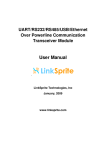
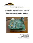
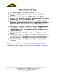
SENS MicroGenius Setup Utility Manual
MicroGenius® Setup Utility
For the SENS MicroGenius® 150 Charger
Configure chargers
with custom settings
Operation Manual
SENS Part Number:
Document Revision:
DCN Number:
Date:
101320
A
106596
August 29, 2014
MADE IN U.S.A.
Installation or service questions?
Call SENS between 8 a.m. and 5 p.m. (Mountain Time),
Monday through Friday, or visit our website.
1840 Industrial Circle
Longmont, CO 80501
Phone: 303.678.7500
800.742.2326
Fax:
303.678.7504
Email: [email protected]
Web: www.sens-usa.com
Copyright © Stored Energy Systems LLC 2014
The SENS name / logo, MicroGenius, and Dynamic Boost1are trademarks of Stored Energy Systems LLC
SENS MicroGenius Setup Utility Manual
TABLE OF CONTENTS
1
2
DESCRIPTION .................................................................................................................................................. 3
SETUP ................................................................................................................................................................. 3
2.1.
Copy Files .................................................................................................................................................. 3
2.3.
Install Utility .............................................................................................................................................. 3
2.4.
Power Off Charger..................................................................................................................................... 3
2.5.
Connect Programming Cable ..................................................................................................................... 3
2.6.
Remove Jumpers........................................................................................................................................ 3
2.7.
Connect Charger ........................................................................................................................................ 4
3
OPERATING INSTRUCTIONS ...................................................................................................................... 4
3.1.
Charger Status............................................................................................................................................ 5
3.2.
File Menu................................................................................................................................................... 5
3.3.
Tools Menu ................................................................................................................................................ 5
3.4.
Help Menu ................................................................................................................................................. 6
3.5.
Find Charger…/Disconnect Charger Button.............................................................................................. 6
3.6.
Charger Setup Tab ..................................................................................................................................... 6
3.7.
CANbus Settings Tab ................................................................................................................................ 6
3.8.
Test/Force Alarms Tab .............................................................................................................................. 6
3.9.
Com Log Tab ............................................................................................................................................. 6
APPENDIX.................................................................................................................................................................. 7
2
SENS MicroGenius Setup Utility Manual
1
DESCRIPTION
Use the MicroGenius® Setup Utility to program MicroGenius® 150 battery chargers with custom settings. This feature
enables an OEM or specially qualified distributor or packager to customize output voltage, alarms, temperature
compensation, boost time limit, and current limit settings.
The MicroGenius® Setup Utility software operates on a Windows 7 or newer PC with a USB port.
2
SETUP
2.1. Copy Files
Copy all files from the media provided by SENS to a Windows 7 or newer PC.
2.2. Install USB Driver
Install the USB driver by double-clicking on the FTDI USB DRIVER AUTO Install.exe file.
2.3. Install Utility
Install the MicroGenius® Setup Utility by double-clicking the MicroGeniusSetupUtilityInstaller.exe file. Launch
the utility if desired.
2.4. Power Off Charger
Disconnect AC and DC voltages from the charger before programming. The USB connection will provide the
power necessary to program the charger.
2.5. Connect Programming Cable
Connect the programming cable provided by SENS from the USB port on a PC to main circuit board connector
J500 (located near bottom left circuit board, just to right of AC connection terminal block) or optional
alarm/communications circuit board connector J6 (located at bottom right circuit board and labeled “SETUP
TOOL”) if the charger is equipped with the optional alarm/communications circuit board.
Figure 1 – Programming Cable Connection
( fully enclosed model with optional alarm/communications circuit board shown)
CONNECTOR J6
ON OPTIONAL
ALARM/COMMS
CIRCUIT BOARD
CONNECTOR
J500 ON MAIN
CIRCUIT BOARD
2.6. Remove Jumpers
Remove all jumpers from JP1 on main circuit board to enable PROGRAM MODE. In PROGRAM MODE the
charger output is determined by values programmed in the charger using the MicroGenius® Setup Utility. If the
charger has not been previously programmed, removing all jumpers will result in an error state.
Figure 2 – Remove Jumpers
JUMPERS
REMOVED
FOR PROGRAM
MODE
3
SENS MicroGenius Setup Utility Manual
2.7. Connect Charger
If not already operating, launch the MicroGenius® Setup Utility. The utility may automatically find the connected
charger or may need to be manually connected by clicking the Find Charger… button at top left of utility. Upon
pressing this button, the charger will connect to the utility and the Find Charger… button will be replaced with a
Disconnect Charger button.
Figure 3 – Remove Jumpers
PRESS TO
CONNECT
CHARGER
TO UTILITY
3
OPERATING INSTRUCTIONS
Use the MicroGenius® Setup Utility to program the parameters listed in Table 1 and described below. The charger will
immediately begin using custom programmed values upon saving to the charger. Screen captures of the MicroGenius®
Setup Utility are provided in the appendix.
Parameter
Float Voltage
Utility Tab
Charger Setup
Boost voltage
Charger Setup
High DC Voltage Alarm
Setpoint
Charger Setup
Low DC Voltage Alarm
Setpoint
Boost Charge Time Limit
Current Limit Setting
Alarm Relay Delay*
Temperature
Compensation Slope
J1939 charger number*
Charger Setup
Table 1 – Programmable Parameters
Access Via Utility and Details
READ/WRITE. Must remove
circuit board JP1 jumpers to engage.
READ/WRITE. Must remove
circuit board JP1 jumpers to engage.
Charger Setup
Charger Setup
Charger Setup
Charger Setup
Adjustment Range
8-32V, must be less than 40% lower
than Boost
8-32V, must be same or higher than
Float, must be less than 40% higher
than Float
READ/WRITE. Must remove
0-35V, must be higher than Boost by
circuit board JP1 jumpers to engage. 2% of Float voltage, must be less than
40% higher than Boost
READ/WRITE. Must remove
0-35V, must be 2-40% lower than
circuit board JP1 jumpers to engage. Float
READ/WRITE
0-100 hours
READ/WRITE
25-100% of rated output current
READ/WRITE
0-60 seconds
READ/WRITE
0 to -0.30%V/°C
CANbus Settings
READ/WRITE
J1939 baud rate*
CANbus Settings
READ/WRITE
J1939 vehicle system
CANbus Settings
READ/WRITE
instance*
J1939 function instance* CANbus Settings
READ/WRITE
J1939 ECU instance*
CANbus Settings
READ/WRITE
J1939 ECU Location*
CANbus Settings
READ/WRITE
SENS Extend Data
CANbus Settings
Enable to receive extended J1939
Enabled*
data from the charger at the master
Test/Force Alarm relays* Test/Force Alarms Force alarm relays ON or OFF
Com Log
Com Log
Log of communications status
*Only available when optional alarm/communications circuit board is included
4
1 or 2, zero indicates CANbus is
disabled due to removed ADDR
jumper on circuit board
31.25kbps-1Mbps
0-15
0-31
0-7
19 character customer defined label
Check box to enable
N/A
N/A
SENS MicroGenius Setup Utility Manual
3.1. Charger Status
The lower section of the MicroGenius® Setup Utility displays read-only charger status.
Figure 4 – Setup Utility Status
CHARGER
STATUS
3.2. File Menu
Access file and save options by selecting the File pull-down menu.
3.2.1.
Open Settings File…
Load/populate the MicroGenius® Setup Utility with settings from a file stored on the PC. Load SENS
factory default settings provided with the utility by selecting the file with appropriate battery type and
number of cells. For example, load file “FloodLeadAcid_6_Cell.uGdata” for a 6 cell/12V flooded lead
acid battery application. Use this option to deploy default or custom settings to a fleet of chargers.
3.2.2.
Save Settings File
Save settings displayed in the MicroGenius® Setup Utility to a file for later use. Saved settings files will
have a .uGdata file extension. Use this option to create and deploy settings to a fleet of chargers.
3.2.3.
Save Settings File As…
Save settings (select save directory) displayed in the MicroGenius® Setup Utility to a file for later use.
Saved settings files will have a .uGdata file extension. Use this option to create and deploy settings to a
fleet of chargers.
3.2.4.
Exit
Exit the MicroGenius® Setup Utility.
3.3. Tools Menu
Access options to update charger firmware or connect charger to MicroGenius® Setup Utility.
3.3.1.
Find Charger…/Disconnect Charger
Select Find Charger… to connect a charger to the MicroGenius® Setup Utility. Ensure the programming
cable is already connected from the PC USB port to the charger. The utility may automatically find the
connected charger or may need to be manually connected by selecting Find Charger…. Upon selecting,
the charger will connect to the utility and Find Charger… will be replaced with Disconnect Charger. Select
Disconnect Charger to disconnect the charger from the utility. The Find Charger…/Disconnect Charger
button performs the same operation as this menu selection.
5
SENS MicroGenius Setup Utility Manual
3.3.2.
Update Firmware…
Select to update MicroGenius® 150 charger firmware. Updated firmware .hex files are available on the
SENS website (www.sens-usa.com). Firmware for the MicroGenius charger is separated into one .hex file
for each the power and optional alarms/communications accessory circuit boards. Upgrade code for each
board independently. Press the Load Charger Firmware button, select the appropriate .hex firmware file
and wait for firmware update to complete. The progress bar at the bottom of the window will display status.
Figure 5 – Updating Firmware
3.4. Help Menu
Access charger user manual, quick-start guide, SENS website, USB port driver and information about the utility.
3.5. Find Charger…/Disconnect Charger Button
Manually connect the charger to the MicroGenius® Setup Utility by clicking the Find Charger… button. Ensure
the programming cable is already connected from the PC USB port to the charger. Upon pressing this button, the
charger will connect to the utility and the Find Charger… button will be replaced with a Disconnect Charger
button. Press the Disconnect Charger button to disconnect the charger from the utility.
3.6. Charger Setup Tab
Configure output voltage, alarms (available with optional alarm/communications circuit board), temperature
compensation, boost time limit, and current limit settings.
Press the Save Changed Values to Charger button to load/save settings to the charger. The charger will
immediately begin using custom programmed values. Press the Update Display With Charger Values button to
refresh the utility display with charger values.
3.7. CANbus Settings Tab
Read and configure J1939 (CANbus) communication values when the charger is equipped with the optional
alarm/communications circuit board. Configurable settings include charger number, baud rate, vehicle system
instance, function instance, ECU instance, and the ability to enable extended data. Select the SENS Extended Data
Enabled checkbox to enable receiving extended J1939 data from the charger at the J1939 master, including low
cranking voltage alarm, low DC voltage alarm, high DC voltage alarm, battery temperature alarm, thermal limit
alarm, invalid settings alarm. Refer to SENS Application Note 21 for information on using J1939 communications.
Press the Save Changed Values to Charger button to load/save settings to the charger. The charger will
immediately begin using custom programmed values. Press the Update Display With Charger Values button to
refresh the utility display with charger values.
3.8. Test/Force Alarms Tab
Test alarm relay operation when the charger is equipped with the optional alarm/communications circuit board.
This feature allows forcing the alarm relays into an alarm state to ensure the relays are operating. Press the Enable
Testing button to allow testing. Press each alarm’s Cycle button to test one alarm at a time or the Test All Alarms
button to test all alarms at the same time. Press the Return to Normal button when finished testing.
3.9. Com Log Tab
Displays real-time communications status.
6
SENS MicroGenius Setup Utility Manual
APPENDIX
Screen captures of the MicroGenius® Setup Utility are provided below.
Charger Setup Tab:
7
SENS MicroGenius Setup Utility Manual
CANbus Settings Tab:
8
SENS MicroGenius Setup Utility Manual
Test/Force Alarms Tab:
9
SENS MicroGenius Setup Utility Manual
Com Log Tab:
10