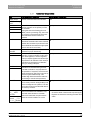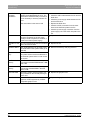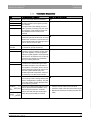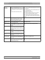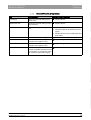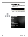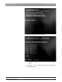
1
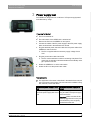
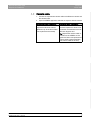
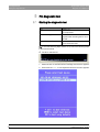
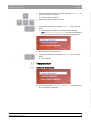
kÉï=~ë=çÑW==
MSKOMNN
`bob`=^`
aá~ÖåçëíáÅ=qççä
båÖäáëÜ
Sirona Dental Systems GmbH
Table of contents
Diagnostic Tool CEREC AC
Table of contents
1
Components of the CEREC AC diagnostic tool .......................................................
3
2
Localizing faults........................................................................................................
4
3
Power supply test .....................................................................................................
5
4
Camera test..............................................................................................................
6
4.1
Monitor power supply ....................................................................................
6
4.2
Bluecam ........................................................................................................
6
4.3
Camera cable ................................................................................................
7
PC diagnostic tool ....................................................................................................
8
5.1
Starting the diagnostic tool ............................................................................
8
5.2
Test procedure ..............................................................................................
9
5.2.1 Customer Diagnostics ........................................................................
9
5.2.2 Technician Diagnostics ......................................................................
11
5.2.3 Sirona Windows Diagnostics..............................................................
13
5.3
Rebooting the PC..........................................................................................
14
5.4
Troubleshooting ............................................................................................
14
5.4.1 Customer Diagnostics ........................................................................
15
5.4.2 Technician Diagnostics ......................................................................
17
5.4.3 Sirona Windows Diagnostics..............................................................
19
Updating the BIOS setting........................................................................................
20
6.1
Determining the BIOS version.......................................................................
23
6.2
Determining the hardware version of the unit ...............................................
23
5
6
2
63 24 599 D3492
D3492.076.03.02.02 06.2011
Sirona Dental Systems GmbH
Components of the CEREC AC diagnostic tool
Diagnostic Tool CEREC AC
1
Components of the CEREC AC diagnostic
tool
● Voltage tester for the PC power supply (Lindy)
● Power button cable for switching on the PC
● Power cable extension for the PC power supply
● Monitor cable (L6)
● PC test tool (software CD)
● Restore CD with BIOS update and BIOS settings
● Camera tester
● Replacement camera cable
båÖäáëÜ
● Instructions for PC and camera diagnosis
63 24 599 D3492
D3492.076.03.02.02
06.2011
3
Localizing faults
Sirona Dental Systems GmbH
Diagnostic Tool CEREC AC
2
Localizing faults
Perform power supply test
Power supply test [ ➙ 5]
Supply power to monitor via camera
tester
Camera test [ ➙ 6]
Check camera and camera cable
with the camera tester
Use PC test tool
4
PC diagnostic tool [ ➙ 8]
63 24 599 D3492
D3492.076.03.02.02 06.2011
Sirona Dental Systems GmbH
Power supply test
Diagnostic Tool CEREC AC
3
Power supply test
The CEREC AC diagnostic tool contains an "ATX power supply tester"
manufactured by "Lindy".
Preparing for the test
✔ The PC is switched off.
✔ The main switch of the CEREC AC is switched off.
2. Connect the cables of the PC power supply to the ATX power supply
tester as described in the attached user manual.
3. Plug the attached power extension cable into the power cable of the
CEREC AC and into the PC.
ª The PC is supplied with the necessary supply voltage of 230
VAC.
4. Plug the power button cable into the PC
ª The PC can be switched on without connecting a keyboard. The
green lamp in the button indicates whether the 5V standby voltage is present in the PC.
5. Switch the CEREC AC on at the main switch.
6. Switch the PC on at the power button cable.
Test procedure
➢ The application of the tester is described in the attached user manual
of the ATX power supply tester. The user manual is available in English, German, French and Italian.
A defective power supply is detec- No defective power supply is deted
tected
The power supply is defective. Re- The power supply is not defective.
place the power supply with a new Plug all cables of the power supply
one.
back into the PC.
Important: Make sure that all cables are plugged back in to the positions where they were originally
located before the test.
63 24 599 D3492
D3492.076.03.02.02
06.2011
5
båÖäáëÜ
1. Remove the PC from the CEREC AC and open it.
Camera test
Sirona Dental Systems GmbH
Monitor power supply
Diagnostic Tool CEREC AC
4
Camera test
Using the camera tester, you can check the monitor power supply, the
Bluecam and the camera cable.
Preparing for the test
✔ The PC is switched off.
1. Unscrew the rear cover of the CEREC AC.
2. Unplug the S-ATA cable for the DVD drive.
3. Plug the S-ATA power supply cable into the S-ATA interface of the
PC where the DVD drive was previously connected.
4. Connect the USB cable to a free USB port of the PC.
5. Switch the PC on and wait until it has finished booting up.
4.1 Monitor power supply
✔ The 12 VDC required for the power supply of the LCD monitor of the
CEREC AC are available at the 4-pole socket of the camera tester.
1. Unplug the power supply cable from the socket of the PC-internal power supply board.
2. Plug it into the corresponding socket of the camera tester.
The monitor shows no function
Replace the monitor (replacement LCD monitor 62 35 951).
4.2 Bluecam
1. Unscrew the Bluecam cable from the PC.
2. Plug it into the socket of the camera tester.
3. Open the CEREC application and take an exposure with the camera.
6
No camera image is displayed
A camera image is displayed
Go on to the next test step.
The supply board in the PC is defective. Replace the supply board
in the PC (replacement supply
board 61 37 421).
63 24 599 D3492
D3492.076.03.02.02 06.2011
Sirona Dental Systems GmbH
Camera test
Diagnostic Tool CEREC AC
Camera cable
4.3 Camera cable
1. Connect the replacement camera cable to the Bluecam camera and
the camera tester.
2. Open the CEREC application and take an exposure with the camera.
No camera image is displayed
A camera image is displayed
The Bluecam camera is defective.
Replace the Bluecam camera
(Bluecam rep. 62 36 884 or Bluecam replacement 62 36 694).
The camera cable was the cause of
the fault. Replace the camera cable with the one attached to the CEREC AC diagnosis tool.
båÖäáëÜ
Tip: Replace the camera cable removed from the CEREC AC diagnosis tool with a new replacement
camera cable (replacement Bluecam camera cable 62 35 845).
63 24 599 D3492
D3492.076.03.02.02
06.2011
7
PC diagnostic tool
Sirona Dental Systems GmbH
Starting the diagnostic tool
Diagnostic Tool CEREC AC
5
PC diagnostic tool
5.1 Starting the diagnostic tool
Test
Suitable for
Customer Diagnostics
Suitable for the user when checking the
PC components.
Technician Diagnostics
Suitable for the technician or service
engineer when checking the PC components.
Sirona Windows Diagnostics
Windows stress test to check the PC
under continuous load.
Tip: If one of the following steps doesn't work, look for the following steps
in the service manual.
✔ The PC is switched off.
1. Switch the PC on and wait until the message shown above appears.
2. Press and hold "F11" on the keyboard until the boot menu appears.
8
63 24 599 D3492
D3492.076.03.02.02 06.2011
Sirona Dental Systems GmbH
PC diagnostic tool
Diagnostic Tool CEREC AC
Test procedure
3. Insert the diagnostic tool CD in the drive and select "CD/DVD:…" in
the menu using the arrow keys.
ª The PC boots from the CD.
4. Wait until the light on the drive goes out.
5. Confirm your selection by pressing the "Return" key on the keyboard.
båÖäáëÜ
ª The diagnostic tool starts and a selection menu appears.
Tip: The "Customer Diagnostics" will start automatically after one minute if you did not press an arrow key beforehand.
6. Select the test with the arrow keys.
7. Confirm your selection by pressing the "Return" key on the keyboard.
ª The test starts.
5.2 Test procedure
5.2.1
Customer Diagnostics
✔ You have started the "Customer Diagnostics" test and the system configuration is displayed.
63 24 599 D3492
D3492.076.03.02.02
06.2011
9
PC diagnostic tool
Sirona Dental Systems GmbH
Test procedure
Diagnostic Tool CEREC AC
1. Check the information in the system configuration to determine whether the system corresponds to the default settings. You can scroll up
and down using the arrow keys.
Tip: The test will start automatically in 3 minutes if you do not press
an arrow key first.
2. Press the "Esc" key on the keyboard.
ª The test starts. The entire test run takes approx. 20 minutes.
ª The result, i.e. "Pass" or "Fail" appears at the end of the test
(see sections entitled "Test result: "Pass" or "Test result: "Fail").
3. On completion of the test, press any key to go on to the test dialog.
Tip: You can scroll to the individual test steps using the arrow keys.
The corresponding result is shown in front of each test step.
4. To quit the test, reboot the PC (see Rebooting the PC [ ➙ 14]).
10
63 24 599 D3492
D3492.076.03.02.02 06.2011
Sirona Dental Systems GmbH
PC diagnostic tool
Diagnostic Tool CEREC AC
Test procedure
Test result: Pass
No fault was found in the PC-specific hardware. A replacement of the PC
component or of the PC makes no sense.
1. Perform the separate test for the supply board.
2. Perform an image restore with the restore set for troubleshooting.
3. Check the service instructions for other possible fault sources.
Test result: Fail
A fault was found in the PC-specific hardware. A replacement of the PC
component or of the PC makes sense when indicated.
An image restore makes no sense.
1. Check to find out which components did not pass the test.
3. Carry out the corresponding steps described in the chapter on Troubleshooting [ ➙ 14] .
5.2.2
Technician Diagnostics
✔ You have started the "Technician Diagnostics" test and the
system configuration is displayed.
1. Check the information in the system configuration to determine whether the system corresponds to the default settings. You can scroll up
and down using the arrow keys.
Tip: The test will start automatically in 3 minutes if you do not press
an arrow key first.
2. Press the "Esc" key on the keyboard.
63 24 599 D3492
D3492.076.03.02.02
06.2011
11
båÖäáëÜ
2. Note the number of the failed test and the error code if available and
report them to the service engineer as soon as possible.
PC diagnostic tool
Sirona Dental Systems GmbH
Test procedure
Diagnostic Tool CEREC AC
ª The test starts. The entire test run takes approx. 20 minutes.
ª The result, i.e. "Pass" or "Fail" appears at the end of the test
(see sections entitled "Test result: "Pass" or "Test result: "Fail").
3. On completion of the test, press any key to go on to the test dialog.
Tip: You can scroll to the individual test steps using the arrow keys.
The corresponding result is shown in front of each test step.
4. To quit the test, reboot the PC (see Rebooting the PC [ ➙ 14]).
Test result: Pass
No fault was found in the PC-specific hardware. A replacement of the PC
component or of the PC makes no sense.
1. Perform the separate test for the supply board.
2. Perform an image restore with the restore set for troubleshooting.
3. Check the service instructions for other possible fault sources.
Test result: Fail
A fault was found in the PC-specific hardware. A replacement of the PC
component or of the PC makes sense when indicated.
An image restore makes no sense.
1. Check to find out which components did not pass the test.
2. Carry out the corresponding steps described in the chapter on Troubleshooting [ ➙ 14] .
3. Note the number of the failed test and the error code if available. Attach this information to the returned PC when replacing a PC.
12
63 24 599 D3492
D3492.076.03.02.02 06.2011
Sirona Dental Systems GmbH
PC diagnostic tool
Diagnostic Tool CEREC AC
Test procedure
5.2.3
Sirona Windows Diagnostics
General
The "Sirona Windows Diagnostics" test simultaneously puts PCspecific components under load over a longer period of time. This time
period is determined by the user.
Due to this load
● the temperature in the PC clearly increases in comparison to normal
operation.
A thermal behavior or any existing faults can thus be detected.
Tip: Do not perform this test unless at least one of the Customer Diagnostics or Technician Diagnostics tests was diagnosed as error-free.
Test procedure
Tip: Let the "Sirona Windows Diagnostics" test run for at least 1
hour. For optimal results, let the test run overnight.
✔ You have started the "Sirona Windows Diagnostics" test and
Windows starts in the test environment. The „Sirona Windows
Diagnostics“ test starts automatically.
➢ Check the result in the "Windows Stress Test" window.
Tip: You may have to reconfigure the windows to enable recognition
of the "Windows Stress Test".
63 24 599 D3492
D3492.076.03.02.02
06.2011
13
båÖäáëÜ
● due to the unlimited time of the test phase, it is more probably that
sporadic faults and errors will be detected.
PC diagnostic tool
Sirona Dental Systems GmbH
Rebooting the PC
Diagnostic Tool CEREC AC
Test result: Pass
No fault was found in the PC-specific hardware. A replacement of the PC
component or of the PC makes no sense.
Test result: Fail
A fault was found in the PC-specific hardware. A replacement of the PC
component or of the PC makes sense when indicated.
An image restore makes no sense.
1. Check the "Windows Stress Test" window to find out which components did not pass the test.
2. Carry out the corresponding steps described in the chapter on Troubleshooting [ ➙ 14] .
Terminating the "Sirona Windows Diagnostics" test.
➢ Click the "Stop" button.
ª The individual test windows are closed.
ª The PC turns off.
5.3 Rebooting the PC
➢ Switch the PC on again via the power button.
5.4 Troubleshooting
The recommended procedure is as follows. If troubleshooting and/or a
component replacement cannot eliminate the fault, replace the PC.
In this case, specify which test was defective when returning the defective
PC.
14
63 24 599 D3492
D3492.076.03.02.02 06.2011
Sirona Dental Systems GmbH
PC diagnostic tool
Diagnostic Tool CEREC AC
Troubleshooting
5.4.1
Customer Diagnostics
Test
Test description / Condition
Action in case of problems
Display Script
Control command without test function
N/A
Activity is rotating
cursor
Test CPU-2
Test NPU-1
Test NPU-2
In the CPU test, the control, address, data ➢ Replace the PC.
and flag registers of the system process
are checked.
During the test of the floating point unit
(NPU, numeric processing unit), the numeric processor of the system and the interface between the two functions are
checked.
Test Timer
In this test, a number is loaded into the
➢ Replace the PC.
three timer channels and it is then checked
whether the countdown is performed in the
three individual channels at the right speed
(not too slow and not too fast).
Test Keyboard
Controller
In this test, the keyboard controller circuit is ➢ Replace the PC.
checked for proper functioning.
Test INT #1
The test tool checks the system interrupt ➢ Replace the PC.
controller. These controllers contain interrupt mask registers, in-service registers,
interrupt request registers and all interrupt
request lines. All channels of the interrupt
controllers are checked for problematic,
wrong or missing interrupts.
Test INT #2
Test DMA #1
Test DMA #2
båÖäáëÜ
Test CPU-1
All registers and status ports of both DMA ➢ Replace the PC.
controllers are checked during this test.
The DMA controller is very important for
the operation of a system, since it has separate channels on which I/O units can access the system RAM directly. This
enables high data transmission rates without having to use the microprocessor.
Test SM Bus
This test is used to check the SM bus. This ➢ Replace the PC.
bus is mainly used for storage battery and
sensor management in systems. The SM
bus is also used to access the SPD data on
the memory modules.
Test WDC___TYP
HDD___Short
Self-Test
A series of nondestructive tests are perfor- 1. Check the SATA cable of the hard drive.
med on the hard drives installed in a sy2. Check the cable of the hard drive power supply.
stem with these functions. Controller
3. Replace the hard drive including the hard drive
search and read tests are performed to
cable.
check the overall condition of a drive.
Test 3 Minute(s)
Drive #1 __Size
of HDD__RndRd
63 24 599 D3492
D3492.076.03.02.02
06.2011
15
PC diagnostic tool
Sirona Dental Systems GmbH
Troubleshooting
Test ATAPI #1
00000000000050000
Diagnostic Tool CEREC AC
Using this function, you can test the in1. Check the CD for scratches or contamination.
stalled CD-ROM/CDRW/DVD drive. The
2. Check the SATA cable between the PC and the
test ROM is checked directly in the test; it
DVD drive.
is not necessary to load any software dri3. Check the power supply cable between the PC
vers.
and the DVD drive.
The test medium is the test tool CD
4. Replace the DVD drive.
5. Check the SATA connection from the mainboard to the SATA slot plate in the PC.
6. Check the power supply connection from the
power supply unit to the SATA slot plate in the
PC.
Test Active
USB test (At least 1 USB human device
must be connected; for the AC, these
usually include a keyboard, a trackball, a
camera and a UPS power supply).
➢ Replace the PC.
Test NET #1 Self- You can use this test to perform an internal ➢ Replace the PC.
Test
test of all network cards.
Test Base Memo- The "base RAM test" can be used to test ➢ Remove the memory and plug it back in.
ry
the base RAM on the system board (up to
640 KB).
Test Cache Memory
This test is used to check the low-level memory data and the low-level addresses in
the external system cache in order to test
its function.
Test Extended
Memory
The "Extended RAM test" makes it possible to test the extended RAM between 1 MB
and 4 GB.
Test Above 4 GB
memory
With the "above 4 GB memory test", you
can test the extended RAM in the area
above 4 GB.
Test VGA RAM
This test is used to test the graphics memory installed on the currently active graphics card.
➢ Replace the graphics card.
Test VESA RAM
With this test, you can check the text and
graphics modes supported by a VESAcompatible graphics card.
➢ Replace the graphics card.
16
63 24 599 D3492
D3492.076.03.02.02 06.2011
Sirona Dental Systems GmbH
PC diagnostic tool
Diagnostic Tool CEREC AC
Troubleshooting
Technician Diagnostics
Test
Test description / Condition
Action in case of problems
Display Test Run
Control command without test function
N/A
Test CPU-1
In the CPU test, the control, address, data ➢ Replace the PC.
and flag registers of the system process
are checked.
During the test of the floating point unit
(NPU, numeric processing unit), the numeric processor of the system and the interface between the two functions are
checked.
Test CPU-2
Test NPU-1
Test NPU-2
Test Timer
In this test, a number is loaded into the
➢ Replace the PC.
three timer channels and it is then checked
whether the countdown is performed in the
three individual channels at the right speed
(not too slow and not too fast).
Test Keyboard
Controller
In this test, the keyboard controller circuit
is checked for proper functioning.
Test INT #1
The test tool checks the system interrupt ➢ Replace the PC.
controller. These controllers contain interrupt mask registers, in-service registers,
interrupt request registers and all interrupt
request lines. All channels of the interrupt
controllers are checked for problematic,
wrong or missing interrupts.
Test INT #2
Test DMA #1
Test DMA #2
Test SM Bus
båÖäáëÜ
5.4.2
➢ Replace the PC.
All registers and status ports of both DMA ➢ Replace the PC.
controllers are checked during this test.
The DMA controller is very important for
the operation of a system, since it has separate channels on which I/O units can access the system RAM directly. This
enables high data transmission rates without having to use the microprocessor.
This test is used to check the SM bus. This ➢ Replace the PC.
bus is mainly used for storage battery and
sensor management in systems. The SM
bus is also used to access the SPD data
on the memory modules.
Test WDC___TYP A series of nondestructive tests are perfor- 1. Check the SATA cable of the hard drive.
HDD___Short Self- med on the hard drives installed in a sy2. Check the cable of the hard drive power supply.
stem with these functions. Controller
Test
3. Replace the hard drive including the hard drive
search and read tests are performed to
cable.
Test 3 Minute(s)
check the overall condition of a drive.
Drive #1 __Size
of HDD__RndRd
63 24 599 D3492
D3492.076.03.02.02
06.2011
17
PC diagnostic tool
Sirona Dental Systems GmbH
Troubleshooting
Test ATAPI #1
00000000000050000
Diagnostic Tool CEREC AC
Using this function, you can test the in1. Check the CD for scratches or contamination.
stalled CD-ROM/CDRW/DVD drive. The 2. Check the SATA cable between the PC and the
test ROM is checked directly in the test; it
DVD drive.
is not necessary to load any software dri3. Check the power supply cable between the PC
vers.
and the DVD drive.
The test medium is the test tool CD
4. Replace the DVD drive.
5. Check the SATA connection from the mainboard to the SATA slot plate in the PC.
6. Check the power supply connection from the
power supply unit to the SATA slot plate in the
PC.
Test Active
USB test (At least 1 USB human device
must be connected; for the AC, these
usually include a keyboard, a trackball, a
camera and a UPS power supply).
➢ Replace the PC.
Test NET #1 SelfTest
You can use this test to perform an internal ➢ Replace the PC.
test of all network cards.
Test Base Memory The "base RAM test" can be used to test ➢ Remove the memory and plug it back in.
the base RAM on the system board (up to
640 KB).
Test Cache Memo- This test is used to check the low-level mery
mory data and the low-level addresses in
the external system cache in order to test
its function.
Test Extended Me- The "Extended RAM test" makes it possibmory
le to test the extended RAM between 1 MB
and 4 GB.
Test Above 4 GB
memory
With the "above 4 GB memory test", you
can test the extended RAM in the area
above 4 GB.
Test VGA RAM
This test is used to test the graphics me- ➢ Replace the graphics card.
mory installed on the currently active graphics card.
Test VESA RAM
With this test, you can check the text and
graphics modes supported by a VESAcompatible graphics card.
18
➢ Replace the graphics card.
63 24 599 D3492
D3492.076.03.02.02 06.2011
Sirona Dental Systems GmbH
PC diagnostic tool
Diagnostic Tool CEREC AC
Troubleshooting
5.4.3
Sirona Windows Diagnostics
Test
Test description
Action in case of problems
Processor(s)
Continuous load and testing of processor cores
➢ Replace the PC.
Motherboard Test
Continuous load and testing of main- ➢ Replace the PC.
board functions
Stress Test Drive
Continuous load and testing of hard
drive
1. Check the SATA cable of the hard drive.
2. Check the cable of the hard drive power
supply.
3. Replace the hard drive including the hard
drive cable.
Continuous load and testing of RAM
2D test
Continuous load and testing of the 2D ➢ Replace the graphics card.
properties of the graphics card
Multimedia Test
Continuous load and testing of the 3D ➢ Replace the graphics card.
properties of the graphics card
USB Test
USB Test
➢ Replace the PC.
(At least one USB human device must
be connected, e.g. a keyboard, trackball, camera or UPS power supply)
63 24 599 D3492
D3492.076.03.02.02
06.2011
➢ Remove the memory and plug it back in.
båÖäáëÜ
Memory Test
19
Updating the BIOS setting
Sirona Dental Systems GmbH
Diagnostic Tool CEREC AC
6
Updating the BIOS setting
✔ You know the hardware version of the unit (see Determining the hardware version of the unit [ ➙ 23]) and the BIOS version (see Determining the BIOS version [ ➙ 23]).
✔ The PC is switched off.
1. Switch on the PC and wait until the above message appears.
2. Hold down the "F11" key on the keyboard until the boot menu appears.
3. Insert the CD containing the BIOS settings tools (CD 63 20 704).
4. Use the arrow keys to select "CD/DVD:…" in the menu and hit the
"Enter" key.
ª The PC boots from the CD.
ª The main menu is displayed.
5. Enter the letter "B" to update the BIOS settings.
20
63 24 599 D3492
D3492.076.03.02.02 06.2011
Sirona Dental Systems GmbH
Updating the BIOS setting
båÖäáëÜ
Diagnostic Tool CEREC AC
6. Confirm the message by pressing any key.
ª You will be prompted to enter your hardware version and BIOS
version.
7. Use the keys "1" to "5" to select the combination of hardware version and BIOS version.
63 24 599 D3492
D3492.076.03.02.02
06.2011
21
Updating the BIOS setting
Sirona Dental Systems GmbH
Diagnostic Tool CEREC AC
ª You will be prompted to confirm your selection.
8. Confirm your selection by pressing the "C" key.
Tip: Pressing the "B" key returns you to your selection.
9. Confirm the message by pressing any key.
ª The Sirona default BIOS settings have been updated.
10. Restart your PC by pressing the "R" key.
22
63 24 599 D3492
D3492.076.03.02.02 06.2011
Sirona Dental Systems GmbH
Updating the BIOS setting
Diagnostic Tool CEREC AC
Determining the BIOS version
6.1 Determining the BIOS version
At PC startup
➢ Switch on the PC.
ª The BIOS version is displayed as shown in the graphic.
båÖäáëÜ
In Windows
➢ Click on "Start"/"All Programs"/"Accessories"/"System programs"/"System information".
ª The system information is opened and the BIOS version can be
read from here.
6.2 Determining the hardware version of the unit
➢ Open the lower rear panel of the unit.
ª The hardware version is shown on the back of the PC.
63 24 599 D3492
D3492.076.03.02.02
06.2011
23
tÉ=êÉëÉêîÉ=íÜÉ=êáÖÜí=íç=ã~âÉ=~åó=~äíÉê~íáçåë=ïÜáÅÜ=ã~ó=ÄÉ=êÉèìáêÉÇ=ÇìÉ=íç=íÉÅÜåáÅ~ä=áãéêçîÉãÉåíëK
«=páêçå~=aÉåí~ä=póëíÉãë=dãÄe=OMNN
aPQVOKMTSKMPKMOKMO MSKOMNN
péê~ÅÜÉW ÉåÖäáëÅÜ
ûKJkêKW= NNQ=OVP
mêáåíÉÇ=áå=dÉêã~åó
páêçå~=aÉåí~ä=póëíÉãë=dãÄe
áå=íÜÉ=rp^W
c~Äêáâëíê~≈É=PN
SQSOR=_ÉåëÜÉáã
dÉêã~åó
ïïïKëáêçå~KÅçã
páêçå~=aÉåí~ä=póëíÉãë=ii`
QUPR=páêçå~=aêáîÉI=pìáíÉ=NMM
`Ü~êäçííÉI=k`=OUOTP
rp^
lêÇÉê=kç
SP=OQ=RVV=aPQVO