1
USOO6392132B2
(12) United States Patent
Uehara
(54)
US 6,392,132 B2
(10) Patent N0.:
(45) Date of Patent:
May 21, 2002
Primary Examiner—Marlon T. Fletcher
(74) Attorney, Agent, or Firm—Morrison & Foerster LLP
MUSICAL SCORE DISPLAY FOR MUSICAL
PERFORMANCE APPARATUS
(75) Inventor: Haruki Uehara, Hamamatsu (JP)
(57)
(73) Assignee: Yamaha Corporation, Hamamatsu (JP)
A musical score display apparatus installed in an electronic
musical instrument such as a player piano is designed to
(*)
Notice:
ABSTRACT
automatically display and change over images of electronic
Subject to any disclaimer, the term of this
patent is extended or adjusted under 35
musical score data on the screen. A user’s voice (or
U.S.C. 154(b) by 0 days.
vocalization) is input by means of a microphone and an A/D
converter, so that the input voice is subjected to signal
processing to produce voice data. The voice data is then
subjected to voice analysis such as phoneme analysis to
(21) Appl. No.: 09/886,758
Jun. 20, 2001
(22) Filed:
Foreign Application Priority Data
(30)
determine an arrangement of phonemes that are included in
(51)
Int. Cl.7 .............................................. .. G09B 15/02
the input voice and that highly matches one of prescribed
Words listed in advance in a Word dictionary. Recognition
data is created based on the arrangement of the phonemes
and is subjected to command interpretation With reference to
(52)
US. Cl. ................. .. 84/477 R; 84/483.1; 84/483.2;
prescribed commands that are listed in advance in a com
Jun. 21, 2000
(JP)
......................................... .. 12-186920
mand database. For example, the command database regis
84/600; 84/609; 84/DIG. 6
(58)
Field of Search ................. .. 84/600—604, 609—612,
ters a command ‘NEXT’ for designating the next page of the
84/615—616, 649—654, 477 R, 478, 483.1,
musical score to be displayed on the screen and a command
‘BACK’ for designating the previous page of the musical
483.2, 484, DIG. 6
score to be displayed on the screen. Herein, one of the
References Cited
(56)
commands that highly matches the recognition data is cho
sen and is used to control images of the musical score being
displayed on the screen. In addition, it is possible to detect
a tone volume or a tempo from the input voice. Thus,
U.S. PATENT DOCUMENTS
5,272,273
5,563,358
5,693,903
5,913,259
6,134,526
A
A
A
A
A
*
*
*
*
*
12/1993
10/1996
12/1997
6/1999
10/2000
Watanuki et al. ........... .. 84/649
Zimmerman ............ .. 84/477 R
musical performance is automatically controlled based on
Heidorn et al. ............. .. 84/609
the electronic musical score data in response to the detected
tone volume or tempo.
Grubb et al.
Kim
............... .. 84/610
.......................... ..
84/634
16 Claims, 10 Drawing Sheets
* cited by examiner
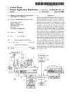
DIGITAL SIGNALS FROM A/D
CONVERTER 230
f
2402 CONTROLLER
241
SIGNAL
PROCESSING
| NSTRUCT I ON
SIGNALS
FOR SIGNAL
PROCESSING
VOICE
DATA
VOICE
J/242
RECOGN l T | ON
{242a
WORD
D l RECT l ONARY
RECOGN l T ION
DATA
244
243
COMMAND
{ RECOGN l T i ON DATA
COMMAND
INTERPRETATION
COMMAND DATA
COMMAND
DATA
5
245
DISPLAY CONTROL
DATABASE
U.S. Patent
May 21, 2002
Sheet 1 0f 10
FIG. 1
US 6,392,132 B2
U.S. Patent
May 21, 2002
Sheet 2 0f 10
arila1/|w4!
US 6,392,132 B2
I
OR
QNN
mzoIl i
m
V
1w
j
@5, 28
wmjogz
E1520 625
7<
@2105
U.S. Patent
May 21, 2002
US 6,392,132 B2
Sheet 3 0f 10
FIG. 3
DIGITAL SIGNALS FROM A/D
240: CONTROLLER
CONVERTER 230
Y
j
241
SIGNAL
PROCESSING
INSTRUCTION
SIGNALS
FOR SIGNAL
VOICE
DATA
PROCESSING
242
Y
Y
2423
Y
VOICE
RECOGNITION
w0RD
DIRECTIONARY
244
RECOGNITION
DATA
243
I
;
COMMAND
COMMAND
RECOGNITION DATA rMDDATADASE
INTERPRETATION
COMMAND DATA
COMMAND
;
[BACKJ
DATA
§
DISPLAY CONTROL
245
U.S. Patent
May 21, 2002
Sheet 4 0f 10
US 6,392,132 B2
L_
N
"I
w.95
U.S. Patent
May 21, 2002
Sheet 5 0f 10
US 6,392,132 B2
FIG. 5
S1
NO
PAGE
FORWARD COMMAND
NPUTTED'?
S2
LAST
PAGE BEING
DISPLAYED?
I83
SUPPLY ELECTRONIC MUSICAL
SCORE DATA OF NEXT PAGE
TO DISPLAY PANEL
@
U.S. Patent
May 21, 2002
Sheet 6 0f 10
US 6,392,132 B2
N
o.6;
0
bf
no
ll
2
ii
U.S. Patent
May 21, 2002
Sheet 7 0f 10
US 6,392,132 B2
FIG. 7
DIGITAL SIGNALS FROM A/D
240a1 CONTROLLER
CONVERTER 230
f
241
SIGNAL
PROCESSING
INSTRUCTION
SIGNALS
FOR SIGNAL
PROCESSING
VOICE
DATA
5242
I
{242a
VOICE
WORD
RECOGNITION
DIRECTIONARY
RECOGNITION
DATA
SONG ‘ WORD {246
POSITION DETECTION
PAGE
INFORMATION
I
245
§
DISPLAY CONTROL
ELECTRONIC MUSICAL
SCORE
DATA 211
FROM STORAGE
U.S. Patent
May 21, 2002
Sheet 8 0f 10
US 6,392,132 B2
FIG. 8
2
INTERVAL DATA 1
RHYTHM DATA 0. 5 3
SONG DATA
ELECTRON I C
5
5
2
5
4
I~
4
1
1 O. 25 3 O. 5 2
+ 11 4 5 a
PAGE DATA
MUSICAL
SCORE DATA
FIG. 9
DIGITAL SIGNALS FROM A/D
CONVERTER 230
§
240b: CONTROLLER
247
PITCH
DETECTION
NOTE STRING
DATA
248
1
ELECTRONIC MUS I CAL
SCORE DATA FROM
STORAGE 21 1
F NOTE
STRING
COMPARISON
PAGE
INFORMATION
245
DISPLAY CONTROL
1
a
U.S. Patent
May 21, 2002
Sheet 9 0f 10
US 6,392,132 B2
FIG. 10
DIGITAL SIGNALS FROM A/D
CONVERTER 230
5
24002 CONTROLLER
241
SIGNAL
7
PROCESSING
INSTRUCTION
SIGNALS
VOICE
FOR SIGNAL
DATA
PROCESSING
5242
I
242a
VOICE
WORD
RECOGNITION
DIRECTIONARY
RECOGNITION
DATA
f
I
249
TEMPO
DETECTION
TEMPO
DATA
I
52 45
DISPLAY CONTROL
FIG. 11
ONE
TWO
THREE
‘
‘I
‘
t0
H
HI I
TEMPO
DETECTION
A t2
t2
#7
U.S. Patent
May 21, 2002
US 6,392,132 B2
Sheet 10 0f 10
~11
\
F___
\/
.65NH
R
\
25 ,
l1
.wz6o5t28m
US 6,392,132 B2
1
2
MUSICAL SCORE DISPLAY FOR MUSICAL
PERFORMANCE APPARATUS
to be displayed on the screen. Herein, one of the commands
that highly matches the recognition data is chosen and is
used to control images of the musical score being displayed
BACKGROUND OF THE INVENTION
on the screen.
The arrangement of the phonemes can be compared With
Words of a song to designate a prescribed position of the
musical score, hence, the corresponding page of the musical
1. Field of the Invention
This invention relates to musical score displays that
display musical scores on screens for musical performance
apparatuses such as player pianos.
2. Description of the Related Art
Recently, electronic musical instruments such as player
score is automatically displayed on the screen.
10
Other than the arrangement of the phonemes, it is possible
to eXtract a string of pitches, by Which retrieval is performed
through the electronic musical score data to ?nd a string of
pianos install functions of displaying musical scores on
notes corresponding to the eXtracted pitches respectively.
screens of displays such as liquid crystal displays.
Hence, the corresponding page of the musical score is
automatically displayed on the screen.
FIG. 12 shoWs an eXample of an image of electronic
musical score data that are displayed on a screen of a display 15
panel of a player piano. Herein, three staves, notes and
In addition, it is possible to detect a tone volume or a
tempo from the input voice. Thus, musical performance is
musical symbols in musical notation are displayed in an
upper area of the screen, While graphical images and control
automatically controlled based on the electronic musical
score data in response to the detected tone volume or tempo.
buttons are displayed in a loWer area of the screen.
Aperformer (or user) Who plays the player piano operates
BRIEF DESCRIPTION OF THE DRAWINGS
the control buttons displayed on the screen to change over
images of the musical score, so that the neXt page of the
musical score is displayed on the screen.
If the performer uses both of his/her hands to play the
player piano, it is necessary for the performer to temporarily
stop playing the player piano and change over the image of
the screen. Alternatively, the performer should rapidly
These and other objects, aspects and embodiments of the
present invention Will be described in more detail With
reference to the folloWing draWing ?gures, of Which:
25
FIG. 1 is a perspective vieW shoWing an appearance of a
player piano that installs a musical score display apparatus
in accordance With a ?rst embodiment of the invention;
change over the image of the screen even if the performer
FIG. 2 shoWs mechanical con?gurations and electrical
does not break the musical performance on the player piano.
In other Words, the conventional player piano needs manual
con?gurations provided inside of the player piano shoWn in
FIG. 1;
operations for changing over images of the musical score on
FIG. 3 is a simpli?ed block diagram shoWing function
the screen, hence, the performer feels dif?culty in continu
ously playing the player piano because the performer cannot
concentrate completely on playing the musical performance.
Other than the aforementioned manual operations for
35
changing over images of the musical score on the screen, the
blocks realiZed in a controller shoWn in FIG. 2;
FIG. 4 shoWs an eXample of an image of a ?rst page of
electronic musical score data being displayed on the screen;
FIG. 5 is a ?oWchart shoWing a page forWard process
being eXecuted by a display control block shoWn in FIG. 3;
conventional player piano needs manual operations, using
FIG. 6 shoWs an eXample of an image of a prescribed page
of electronic musical score data incorporating a practice
the control buttons, for setting or changing tone volumes and
tempos in performance. To set or change them, the per
mark on the screen;
former may have a similar problem due to intermittent
FIG. 7 is a simpli?ed block diagram shoWing function
suspension of the musical performance on the player piano.
blocks realiZed in a controller in accordance With a second
SUMMARY OF THE INVENTION
It is an object of the invention to provide a musical
embodiment of the invention;
45
performance apparatus installing a musical score display
apparatus Whose operations can be easily controlled by
FIG. 8 shoWs an eXample of a con?guration of electronic
musical score data that are used in the second embodiment;
FIG. 9 is a simpli?ed block diagram shoWing function
voice commands spoken by a user.
The present invention provides a musical score display
apparatus that is installed in an electronic musical instru
ment such as a player piano and that is designed to auto
blocks realiZed in a controller in accordance With a modi?ed
matically display and change over images of electronic
embodiment of the invention;
FIG. 11 is a time chart that is used to eXplain operations
eXample of the second embodiment;
FIG. 10 is a simpli?ed block diagram shoWing function
blocks realiZed in a controller in accordance With a third
musical score data on the screen. A user’s vocaliZation (or
user’s voice) is input by means of a microphone and an A/D
converter, so that the input voice is subjected to signal
processing to produce voice data. The voice data is then
subjected to voice analysis such as phoneme analysis to
of the controller of the third embodiment in Which count
55
determine an arrangement of phonemes that are included in
the input voice and that highly match one of the prescribed
Words listed in advance in a Word dictionary. Recognition
data is created based on the arrangement of the phonemes
and is subjected to command interpretation With reference to
prescribed commands that are listed in advance in a com
mand database. For eXample, the command database regis
ters a command ‘NEXT’ for designating a neXt page of the 65
musical score to be displayed on the screen and a command
‘BACK’ for designating a previous page of the musical score
voices are input to the player piano; and
FIG. 12 shoWs an eXample of an image of electronic
musical score data that are displayed on the screen.
DESCRIPTION OF THE PREFERRED
EMBODIMENTS
This invention Will be described in further detail by Way
of examples With reference to the accompanying draWings.
[A] First Embodiment
(1) Con?gurations of First Embodiment
FIG. 1 shoWs an appearance of a player piano 200,
internal con?gurations of Which are shoWn in FIG. 2.
US 6,392,132 B2
3
4
First, a mechanical con?guration of the player piano 200
Will be described With reference to FIG. 2. The player piano
stoppers 8. In other Words, the controller 240 performs
200 provides an action mechanism 3 for transmitting an
action (i.e., touch or depression) of a key 1 to a hammer 2,
a string 4 being struck by the hammer 2, a solenoid 5 for
tones being generated by striking the strings 4. As described
above, the player piano 200 provides ‘electronic’ musical
musical tone suppression controls to suppress the musical
tone generation controls in addition to the ‘mechanical’
musical tone generation controls that are made by actually
driving the key 1 to move, a damper 6 for stopping vibration
of the string 4, and a mute mechanism containing a stopper
8 for regulating movement of the hammer, Wherein the
striking the strings 4. Herein, the electronic musical tone
mechanical members that are generally installed in the
generation controls are made such that electronic musical
tones are controlled in response to the performance data by
supplying control signals to the electronic musical tone
generator 222, Which is con?gured by a sound source and a
pianos. For example, the player piano 200 also provides a
speaker (or speakers).
stopper 8 can move in directions of arroWs in FIG. 2. Of
course, the player piano 200 also provides the knoWn
10
The player piano 200 of the present embodiment also
back check 7 for preventing the hammer 2 from unneces
sarily moving or deviating. The present speci?cation
excludes description of the aforementioned mechanical
provides a microphone 220 and an analog-to-digital con
15
verter (A/D converter) 230.
The microphone 220 has a directivity in a prescribed
direction. Therefore, the microphone 220 is mounted on a
certain location of the player piano 200 at Which it can
members that are not closely related to essential matters of
the present embodiment.
Next, an electric con?guration of the player piano 200
Will be described With reference to FIG. 2, Wherein the
ef?ciently pick up the voice of the user (see FIG. 1). The
player piano 200 is basically con?gured using the general
microphone 220 picks us the user’s voice and converts it to
electronic components such as the CPU, ROM and RAM.
Namely, a controller 240 performs overall controls on the
player piano 200. A servo controller 212 controls a servo
mechanism based on control signals output from the con
troller 240. An electronic musical tone generator 222 gen
erates electronic musical tones based on control signals
output from a key sensor 221, Which Will be described later.
analog signals. The A/D converter 230 converts the analog
signals to digital signals, Which are forWarded to the con
troller 240.
Namely, the controller 240 receives user’s voice com
25
Adisplay panel 250 is con?gured by a liquid crystal display
mands (or user’s vocaliZed commands), Which are picked up
and supplied thereto by the microphone 220 and the A/D
converter 230. RecogniZing the user’s voice commands, the
controller 240 performs image changeover controls for
to display images of electronic musical score data on a
screen. In addition, a storage unit 211 stores electronic
changing over images of the musical score on the screen of
the display panel 250. That is, the controller 240 has the
image changeover controls in addition to the foregoing
musical score data and performance data therein.
Based on the performance data supplied from the storage
performance controls such as the mechanical and electronic
unit 211, the controller 240 supplies controls signals to the
musical tone generation controls.
Next, display image controls of the controller 240, Which
are characteriZing features of the present invention, Will be
servo controller 212 in order to control positions of the keys
1 at prescribed times respectively.
Speci?cally, based on the control signal supplied from the
35
described With reference to FIG. 3.
tion current, corresponding to the prescribed position of the
FIG. 3 shoWs simpli?ed function blocks provided inside
of the controller 240. Namely, the controller 240 provides a
key 1, to How across the solenoid 5 corresponding to the key
signal processing block 241, a voice recognition block 242,
1. In addition, the servo controller 212 inputs a feedback
a command interpretation block 243, a command database
244 and a display control block 245.
controller 240, the servo controller 212 produces an excita
signal Vy from the solenoid 5. Using such a feedback signal
The signal processing block 241 performs signal process
Vy, the servo controller 212 performs a feedback control of
ing on digital signals output from the A/D converter 230, so
the excitation current to be ?oWn across the solenoid 5
corresponding to the key 1. Further, the controller 240
performs a positioning control on the stopper 8 by
adequately turning on or off a drive mechanism (not shoWn).
As described above, based on the performance data sup
that voice data are created and are forWarded to the voice
45
the signal processing in response to instruction signals being
supplied from the voice recognition block 242.
The voice recognition block 242 divides the voice data,
output from the signal processing block 241, into plural data
by units of frames (hereinafter, simply referred to as “frame
plied from the storage unit 211, the controller 240 performs
positioning controls respectively on the solenoids 5 corre
sponding to the keys 1 by means of the servo controller 212.
Thus, it is possible to perform ‘mechanical’ musical tone
data”). Sound models are created based on phoneme models,
Which are registered in advance. Phoneme analysis is per
formed by comparison betWeen the frame data and sound
models, Waveforms of Which are compared With each other.
generation controls for actually striking the strings 4.
The player piano 200 provides the prescribed number of
keys 1, Which are respectively coupled With key sensors 221.
The key sensors 221 are provided to detect operations of the
55
keys 1 respectively.
Thus, the phoneme analysis determines phonemes having
high likelihood in Which the frame data highly match With
the sound models in their Waveforms. That is, the voice
recognition block 242 effects phoneme analysis processes to
The key sensors 221 are arranged beneath loWer surfaces
of the keys 1, so that they output signals representing
variations of states of the keys 1 (namely, depression and
release of the keys 1) to the controller 240.
Based on output signals of the key sensors 221, the
controller 240 supplies control signals to the electronic
musical tone generator 222 to control generation of elec
tronic musical tones. When electronically generating the
musical tones in response to operations of the keys 1, the
controller 240 stops the hammers 2 striking the strings 4 by
performing the aforementioned positioning controls on the
recognition block 242. It is possible to change the content of
provisionally determine arrangements of the phonemes,
Which are respectively compared With Words that are regis
tered in a Word dictionary 242a in advance. Thus, the voice
recognition block 242 chooses the Words that highly match
With the arrangements of the phonemes. Using those Words,
the voice recognition block 242 performs syntax analysis
65
using language models. Through the syntax analysis, the
voice recognition block 242 determines a sentence (or
statement) that can be read in the Japanese language, for
US 6,392,132 B2
5
6
example. Then, the voice recognition block 242 produces
recognition data representing the determined sentence,
FIG. 4 shoWs an example of the ?rst page of the musical
score being displayed on the screen of the display panel 250.
Which are forwarded to the command interpretation block
The display panel 250 displays basically three types of
information, namely performance information ‘a’, tempo
243. Incidentally, the Word dictionary 242a registers in
advance the prescribed Words regarding the commands for
use in controls of automatic performance of the player piano
200. For example, it registers the Words such as “start” and
“stop” that instruct start and stop of the automatic perfor
mance respectively. In addition, the Word dictionary 242a
also registers other Words regarding the commands for use
information ‘b’ and title information ‘c’, on the screen. The
information ‘a’ corresponds to the ?rst page of the musical
score shoWing three staves on Which musical symbols and
musical notes designating pitches and duration are
adequately arranged in the prescribed musical notation.
10
Hence, the user is able to play the player piano 200 With
in changeovers of images of electronic musical score data on
reference to the musical score displayed on the screen.
the screen. For example, it registers the Japanese Words such
as T‘) 5% and 732‘. (i.e., “next” and “back” in English) that
instruct the display panel 250 to change over images of the
user uses as the standard of velocity in musical performance
on the musical score. In the case of FIG. 4, the tempo
The tempo information ‘b’ designates a tempo that the
electronic musical score data on the screen. Herein, “TUGI” 15
information b designates a certain performance tempo by
instructs the display panel 250 to display the next page
folloWing the page presently displayed on the screen, While
“MAE” instructs the display panel 250 to display the pre
Which sixty quarter notes are to be played Within one minute.
Incidentally, the user is able to arbitrarily set or change the
vious page on the screen.
the user sets the performance tempo on the screen, the
The command interpretation block 243 compares the
recognition data output from the voice recognition block 242
With command data representing the prescribed commands
that are registered in the command database 244 in advance.
display control block 245 controls the display panel 250 to
performance tempo by operating the operator console. Once
sequentially ?ash the notes that the user should play in
response to the performance tempo, Which is displayed as
the tempo information b in an upper left portion of the
Through comparison, the command interpretation block 243
interprets the recognition data to choose the commands that
highly match With the recognition data. Herein, the com
screen.
25
The title information ‘c’ shoWs the title of the musical
tune, the name of a composer, etc. The title information c
mand interpretation block 243 chooses a command having a
also contains information representing the present position
highest degree of match (namely, a voice input command)
and other examples of commands that have relatively high
of the musical score of the musical tune being presently
played in accordance With progression of musical perfor
mance. For example, the information shoWs a serial number
of the measure that is counted from a ?rst measure of the
musical score of the musical tune.
degrees of match. The chosen commands are converted to
command data to suit the prescribed data format that can be
uniquely interpreted for the display control block 245. The
command data are supplied to the display control block 245.
The command database 244 manages the Words regarding
the commands for changing over images of the electronic
Suppose that the user produces the Word “TUGI” on the
35
microphone 220 of the player piano 200 under the condition
Where the display panel 250 is presently displaying the ?rst
musical score data on the screen in correspondence With the
page of the musical score on the screen. In that case, the
command data respectively. Concretely speaking, FIG. 3
display panel 250 to display the next page of the electronic
Word “TUGI” is picked up by the microphone 220 and is
converted to digital signals by the A/D converter 230. Upon
receipt of the digital signals, the controller 240 starts voice
recognition processes and the like. Concretely speaking, the
user’s voice is input to the player piano 200 by means of the
microphone 220 and A/D converter 230, so that the signal
musical score data on the screen. In addition, the Word
processing block 241 produces the corresponding voice
“MAE” for designating the previous page of the electronic
data, Which are forWarded to the voice recognition block
shoWs an example of the content of the command database
244 in Which the Word “TUGI” for designating the next page
of the electronic musical score data to be displayed on the
screen is related to the command ‘NEXT’ for instructing the
musical score data to be displayed on the screen is related to 45 242. In the voice recognition block 242, the voice data are
the command ‘BACK’ for instructing the display panel 250
to display the previous page of the electronic musical score
data on the screen.
Based on the command data output from the command
interpretation block 243, the display control block 245
performs various types of display controls such as
changeovers of images of the electronic musical score data
to be displayed on the screen of the display panel 250.
(2) Operations of First Embodiment
Next, operations of the player piano 200 Will be described
55
With respect to a user’s musical performance in accordance
With the ?rst embodiment of the invention.
respect to the electronic musical score data. Therefore, the
voice recognition block 242 determines the Word “TUGF”
based on the phoneme analysis result, so that corresponding
recognition data are forWarded to the command interpreta
tion block 243. Upon receipt of the recognition data from the
First, the user of the player piano 200 operates an operator
console (not shoWn) to select a musical tune to be per
formed. Then, the display control block 245 reads from the
storage unit 211, electronic musical score display data
corresponding to the selected musical tune. The display
voice recognition block 242, the command interpretation
block 243 refers to the command database 244 to make a
determination as to Which command the recognition data
control block 245 produces electronic musical score data for
displaying a ?rst page of the musical score on the screen.
The electronic musical score data are supplied to the display
panel 250. Thus, the display panel 250 displays the ?rst page
of the musical score on the screen.
subjected to phoneme analysis to provisionally determine an
arrangement of phonemes included in the user’s voice. The
arrangement of the phonemes is compared With the Words
that are registered in the Word dictionary 242a. Thus, the
voice recognition block 242 chooses a Word that highly
matches With the arrangement of the phonemes Within the
Words registered in the Word dictionary 242a. The Word
dictionary 242a coupled With the voice recognition block
242 registers the Word “TUGI” that indicates a page migra
tion in the forWard direction (namely, page forWard) With
65
actually means. As described before, the command database
244 stores the Word “TUGI” representing the page forWard
of the electronic musical score data in correspondence With
the command NEXT for instructing the page forWard of the
US 6,392,132 B2
7
8
electronic musical score data on the screen. Therefore, the
prescribed factors (Which range betWeen ‘1’ and ‘10’, for
command interpretation block 243 reads from the command
database 244, the command NEXT that corresponds to the
example) on the screen, and it is possible to provide a
recognition data output from the voice recognition block
of electronic musical score data can be divided into multiple
sections being arranged in a vertical direction on the screen.
For example, an image of the electronic musical score data
is divided into tWo sections, Which are respectively dis
division function (or screen split function) by Which images
242. Then, the command NEXT is sent to the display control
block 245.
Receiving the command NEXT from the command inter
pretation block 243, the display control block 245 starts to
played in an upper area and a loWer area on the screen. In
as to Whether a page forWard command ‘NEXT’ for the
order to facilitate the aforementioned functions, the Word
dictionary 242a of the voice recognition block 242 and the
command database 244 register a Word “Zoom” for desig
electronic musical score data is input or not. If the display
control block 245 detects the page forWard command NEXT
score data and a Japanese Word ‘fl/711i)‘ or “BUNKATSU”
execute a page forWard process shoWn in FIG. 5. Herein, the
How ?rstly proceeds to step S1 in Which a decision is made
10
nating magni?cation of images of the electronic musical
(i.e., “divide” in English) for designating division of images
being output from the command interpretation block 243,
the How proceeds to step S2 in Which a decision is made as
to Whether the last page of the musical score is presently
displayed on the screen or not. If “YES” in step S2, the
15
display control block 245 immediately ends the page for
Ward process. If the display control block 245 determines in
step S2 that the display panel 250 does not display the last
of the electronic musical score data. In addition, the com
mand database 244 also registers a command ‘EXPAND’ in
relation With the Word “Zoom” and a command ‘DIVIDE’ in
relation With the Word “BUNKATSU”. Thus, the user is able
to freely change over the siZes and shapes of the electronic
musical score data on the screen of the display panel 250 by
his/her voice commands.
page of the musical score on the screen, in other Words, if
(b) Second Modi?ed Example
“NO” in step S2, the How proceeds to step S3 in Which the
display control block 245 reads from the RAM (not shoWn),
250 displays the next page of the musical score on the
The ?rst embodiment originally describes that the elec
tronic musical score data are con?gured by the performance
information ‘a’, tempo information ‘b’ and title information
‘c’ (see FIG. 4). It is possible to additionally introduce a
screen.
practice mark ‘d’, Which is displayed at an arbitrary position
the next page of electronic musical score data, Which are
supplied to the display panel 250. Thus, the display panel
25
The aforementioned description is made With respect to
Within the area of the performance information ‘a’ on the
the case Where the Word “TUGI” for designating the next
screen.
page of the musical score is input to the player piano 200.
Similar operations and processes are made With respect to
another case Where the Word “MAE” for designating the
previous page of the musical score is input to the player
Concretely speaking, the controller 240 incorporates a
practice mark Write tool, Which operates responsive to user’s
manual operation of the operator console. That is, by manu
ally operating the operator console, the user is able to
piano 200.
According to the player piano 200 of the present embodi
ment described above, When the user speaks the prescribed
display a practice mark ‘d’ at an arbitrary position Within the
35 area of the performance information ‘a’ on the screen. FIG.
6 shoWs that a letter ‘A’ is displayed as the practice mark ‘d’
above a loWest staff Within three staves of the performance
information ‘a’ on the screen. Incidentally, the practice mark
‘d’ is not necessarily limited to one prescribed symbol such
keyWord toWard the microphone 220, the display panel 250
correspondingly changes over images of the musical score
being displayed on the screen. Therefore, even When the user
plays the player piano 200 With both of his/her hands, the
as the letter ‘A’. Therefore, it is possible to provide plural
user is able to change over the images on the screen of the
display panel 250 Without intermittently breaking musical
symbols such as letters ‘A’ and ‘B’ as the practice mark ‘d’.
In addition, it is possible to arbitrarily add or delete the
performance on the player piano 200. Thus, the user is able
practice mark d on the screen.
to concentrate his/her mind on the musical performance of
the player piano 200.
45
To realiZe incorporation of the practice mark d, the Word
dictionary 242a of the voice recognition block 242 and the
The present embodiment originally describes that the
command database 244 register a Word “MARK A” for
display panel 250 merely displays images of the electronic
designating the practice mark ‘A’ to be incorporated into the
musical score data on the screen. In this case, the display
electronic musical score data being displayed on the screen.
panel 250 is not necessarily designed to display control
buttons for the user’s manual operations together With the
In addition, the command database 244 also registers a
command ‘JUMP A’ in relation With the Word “MARK A”.
If the controller 240 is con?gured to incorporate the
practice mark Write tool described above, the user can
musical score on the screen. For this reason, even if the
display panel 250 employs the same siZe of screen being
conventionally used, it is possible to broaden the overall area
instruct the display panel 250 to display images of electronic
for displaying the musical score on the screen compared
With conventional displays.
55
(3) Modi?ed Examples
(a) First Modi?ed Example
Suppose that the display panel 250 initially displays an
The ?rst embodiment originally describes that images of
image of electronic musical score data of page 10, Which
differs from an image of electronic musical score data of
page 2 incorporating a practice mark ‘A’, on the screen. In
this case, When the user Wishes to practice the prescribed
part of the musical score With reference to the image of the
electronic musical score data incorporating the practice
mark ‘A’, the user speaks Words “MARK A” toWard the
electronic musical score data being displayed on the screen
of the display panel 250 are changed over in response to
human voices (or user’s voice commands). Instead of chang
ing over the images of the electronic musical score data, it
is possible to change over siZes and shapes of staves and
musical symbols of the musical score on the screen in
response to the human voices. Concretely speaking, it is
possible to provide a magni?cation function by Which
images of electronic musical score data can be magni?ed by
musical score data together With the practice mark ‘A’ on the
screen at any time. Concrete operations Will be described
beloW.
65
microphone 220 of the player piano 200. Inputting such
Words by means of the microphone 220, the command
interpretation block 243 reads the command ‘JUMP A’
US 6,392,132 B2
9
10
corresponding to the registered Word “MARK A” from the
command database 244, so that the corresponding command
displayed at the prescribed position on the screen. In that
case, the user is also able to change over images of the
data is forWarded to the display control block 245. Based on
musical score on the screen by his/her voice.
the command data output from the command interpretation
block 243, the display control block 245 supplies the elec
musical score data at measure number 33 Which appears on
Suppose that a practice mark A is added to the electronic
tronic musical score data of page 2 incorporating the prac
page 3 of the musical score, for example. In this case, When
the user speaks the Words “MARK A” toWard the micro
tice mark ‘A’ to the display panel 250. Thus, the display
panel 250 automatically changes over images of the musical
phone 220 of the player piano 200, the display panel 250
score on the screen from page 10 to page 2.
automatically displays on the screen, the musical score of
If the controller 240 is con?gured as described above, the
user is able to display images of the electronic musical score
data together With the practice mark on the screen by simple
page 3 in Which the practice mark A has been already
displayed at the prescribed position. In order to facilitate an
image changeover With respect to the musical score of the
prescribed page incorporating the practice mark A on the
operations.
(c) Third Modi?ed Example
The second modi?ed example describes that the user
screen, it is necessary to provide the user With information
15
manually operates the operator console to add a practice
musical score. In order to do so, it is possible to display the
measure number and page of the musical score, to Which the
mark to the musical score on the screen. Of course, this
practice mark Ais added, in the area of the title information
technique is applicable to a system in Which the user
designates a position of a practice mark to be displayed on
‘c’ on the screen.
(d) Fourth Modi?ed Example
the screen by his/her voice. Concretely speaking, the Word
dictionary 242a and the command database 244 register the
Japanese Words “KAKIKOMI MODE” (i.e., “Write mode”
in English) for designating a changeover operation from an
automatic performance mode to a practice mark Write mode.
In addition, the command database 244 also registers a
command ‘MODE WRITE’ in relation With the Words
regarding the position of the practice mark A Within the
The third modi?ed example described the con?guration of
the apparatus in Which the display panel 250 automatically
displays an image of the electronic musical score data of the
prescribed page, Which is speci?ed by the practice mark and
25
“KAKIKOMI MODE”.
In order to designate a position of a practice mark to be
displayed on the screen, the user speaks the Words “KAK
measure number. Instead, it is possible to directly input a
voice command for designating the speci?c page of the
electronic musical score data incorporating the practice
mark.
(e) Fifth Modi?ed Example
IKOMI MODE” toWard the microphone 220 of the player
piano 200. Thus, the player piano 200 is set in a practice
mark Write mode. To further designate the concrete position
of the practice mark on the screen, the user speaks Words
images of electronic musical score data of multiple pages are
changed over on the screen With reference to the practice
“SHOSETSU BANGO 11” (i.e., “measure or bar number
electronic musical score data of multiple pages on the screen
11” in English) and “MARK A” toWard the microphone 220.
Herein, “11” that is spoken to folloW “SHOSETU BANGO”
The second and third modi?ed examples describe that
mark. Instead, it is possible to change over images of
35
With reference to the measure number (i.e., the serial number
of the measure that is counted from the ?rst measure of the
musical score of the musical tune), Which is designated by
the user. As described before, the display panel 250 displays
is a serial number of the measure or bar that is counted from
the ?rst measure or bar Within the musical score, While “A”
that is spoken to folloW “MARK” is an alphabetic letter that
in the area of the title information c on the screen, infor
is selected from among plural practice marks A, B, . . . , for
mation indicating the number of the measure that is counted
example. All of the aforementioned Words and commands
are registered in the Word dictionary 242a and the command
database 244 in advance. When the user speaks the Words of
from the ?rst measure of the musical score of the musical
tune and is being presently played by the user. This infor
mation is very useful for the user, particularly in the practice
of the musical performance on the player piano 200. That is,
“SHOSETSU BANGO 11” and “MARK A” toWard the
microphone 220 of the player piano 200, the controller 240
automatically inputs the prescribed command that instructs
45
the user memoriZes the number of the measure (e.g., mea
sure number ‘11’) of the musical score at Which the user
the display panel 250 to display a practice mark A at a
frequently makes errors, in spite of repeatedly practicing
position of measure number 11 on the screen. Thus, the
many times. Therefore, the user can easily instruct the
display panel 250 additionally displays the practice mark A
display panel 250 to display the prescribed page of the
at the position of the measure number 11 of the musical
electronic musical score data incorporating the practice
mark by designating the memoriZed measure number.
Incidentally, the aforementioned ?fth modi?ed example that
score Within the area of the performance information ‘a’ on
the screen.
As described above, if the apparatus alloWs the user to
alloWs the user to change over the pages of the electronic
musical score data by designating the measure numbers can
designate the position of the practice mark on the screen by
his/her voice, it is possible to additionally display the
55
practice mark at the desired position Within the musical
score on the screen even if the user cannot presently use both
of his/her hands because of progression of musical perfor
mance on the player piano 200, for example.
As described above, designation of the position of the
tion.
(6) Sixth Modi?ed Example
The ?rst embodiment and its modi?ed examples describe
practice mark on the screen can be made by the user’s voice
because the electronic musical score data do not originally
that pages of electronic musical score data are changed over
on the screen in response to the user’s voice. In the case
designate the position of the practice mark in advance.
Instead, designation of the position of the practice mark can
be made using a prescribed format of the electronic musical
score data by Which the practice mark is added to the
performance information ‘a’ so that it is automatically
be easily actualiZed using the same con?guration of the
controller 240 employed in the ?rst modi?ed example,
hence, the description of the controller 240 for use in the
?fth modi?ed example is omitted in the present speci?ca
Where the pre-recorded musical performance is reproduced
65
on the player piano 200 in the automatic performance mode
and the like, it is possible to change over positions of
reproduction of the musical performance in response to
US 6,392,132 B2
11
12
changeovers of pages of the musical score being displayed
of the composer, name of the metrician, etc., Which are not
on the screen. This function can be actualiZed by providing
closely related to the present invention, hence, the descrip
a reproduction position control block subsequent to the
command interpretation block 243. The reproduction posi
tion thereof Will be omitted.
The interval data expresses seven musical intervals for
tion control block makes a determination as to Which part of 5
solfa syllables ‘do’ (C) to ‘si’ (B) by numbers, Wherein ‘0’
the performance data is to be reproduced on the basis of the
is allocated to ‘do’, and semitone is expressed using the
number ‘1’. In the musical scale, ‘do’ sharp (#) that is a
command data output from the command interpretation
semitone higher than ‘do’ is expressed by the number ‘1’,
block 243. In response to the determination result, the
and ‘re’ that is a semitone higher than ‘do’ sharp is expressed
by ‘2’, for example. In addition, a symbol ‘+’ is used to
reproduction position control block outputs control data to
the electronic musical tone generator 222, so that the repro
duction position is to be changed over in the musical score.
Based on the control data, the electronic musical tone
express one octave higher than the reference note in the
certain musical scale, and a symbol ‘—’ is used to express one
octave loWer than the reference note in the certain musical
generator 222 generates musical tones, by Which the musical
performance is reproduced in accordance With the electronic
musical score data Whose pages are successively changed
over on the screen. In the reproduction of the performance
data described above, the electronic musical tone generator
222 is controlled by the control data. In the automatic
scale. Those symbols are Written in the left positions of the
numbers shoWing the intervals (or notes). For example, ‘+1’
15
indicates a note of ‘do’ sharp that is one semitone and one
octave higher than the reference note ‘do’.
The rhythm data are expressing using units of quarter
note lengths, Wherein one quarter-note length is expressed
performance that is realiZed With sequential changeovers of
by the number ‘1’. For example, ‘0.5’ expresses a half of the
quarter note, namely an eighth note, and ‘4’ expresses a
pages of the electronic musical score data on the screen, the
servo controller 212 is to be controlled based on the control
Whole note corresponding to a sum of four quarter notes.
The song data are created in the text form that describes
data. Because the automatic performance can be easily
realiZed by partially modifying the reproduction of the
an arrangement of Words (or syllables) in the prescribed
performance data, details of the automatic performance on
the player piano 200 are omitted in the present speci?cation.
[B] Second Embodiment
order, Wherein the Words are described at the prescribed
25
(1) Con?guration of Embodiment
positions in connection With the pitch data and rhythm data
respectively. FIG. 8 shoWs Japanese syllables such as
f7 f7 77'
(i.e., “la la la . . . ” in English).
The page data shoWs a number of the page of the
The ?rst embodiment is designed such that the controller
240 performs display controls on the electronic musical
electronic musical score data to Which the pitch data, rhythm
score data in response to the user’s voice commands. The
data and song data presently belong.
second embodiment is designed such that a controller 240a
performs display controls on the electronic musical score
data in response to Words of a song Which are actually sung
by the user. The second embodiment employs the same
necessarily described in the aforementioned format shoWn in
FIG. 8. Hence, it is possible to use pitch data instead of the
interval data.
hardWare con?guration of the player piano 200 shoWn in
FIG. 2, hence, the description thereof Will be omitted.
Incidentally, the electronic musical score data are not
35
FIG. 7 shoWs function blocks for use in the controller
240a in accordance With the second embodiment. As com
(2) Operations of Second Embodiment
Next, a description Will be given With respect to opera
tions of the second embodiment. Herein, the description is
made in consideration of the situation Where the user sings
a song on the microphone 220 of the player piano 200 While
pared With the ?rst embodiment shoWn in FIG. 3, the
controller 240a additionally provides a song Word position
detection block 246, Which is substituted for the aforemen
tioned command interpretation block 243 and the command
database 244.
The song Word position detection block 246 operates
the display panel 250 sequentially changes over images of
electronic musical score data on the screen in the automatic
performance mode.
When the user 220 sings a song on the microphone 220
While pronouncing Words of the song by each of syllables,
responsive to Words of a song of a musical tune that are 45
the controller 240a starts voice recognition processes.
Suppose that the user presently pronounces a Word of the
song of “TONAKAI” (i.e., “reindeer” in English), Which is
made up of four Japanese syllables, on the microphone 220.
The aforementioned user’s voice is input to the player
piano 200 by means of the microphone 220 and A/D
sequentially sung by the user on the microphone 220. Based
on the electronic musical score data being transferred from
the storage unit 211, the song Word position detection block
246 detects a position of the song containing plenty of Words
(or phonemes) one of Which presently matches With the
converter 230, so that the corresponding voice data are
Word (or phoneme) of the song that is presently produced
supplied to the voice recognition block 242 by means of the
from the user’s mouth and is picked up by the microphone
220. Then, the song Word position detection block 246
242 performs phoneme analysis (or syllable analysis) on the
signal processing block 241. The voice recognition block
input voice data to provisionally determine an arrangement
outputs a detection result to the display control block 245. In
the above, the song Word detection block 246 performs
55
position of the song presently matched With the Word of the
song actually produced from the user’s mouth. Herein, the
electronic musical score data are described in a table form,
an example of Which Will be described With reference to
FIG. 8.
FIG. 8 shoWs a main portion of the con?guration of the
electronic musical score data. Herein, the electronic musical
score data are con?gured by multiple sets of data, namely
interval data, rhythm data, song data and page data. Other
than these data, the electronic musical score data also
contain data representing the title of the musical tune, name
of phonemes (or syllables), Which is compared With Words
that are registered in the Word dictionary 242a in advance.
Then, the voice recognition block 242 chooses a Word
retrieval on the electronic musical score data to ?nd out the
65
having the highest degree of match. In the second
embodiment, the Word dictionary 242a of the voice recog
nition block 242 registers a variety of Words, Which are used
for various songs, in addition to the prescribed Words that
are related to the prescribed controls of the player piano 200.
Therefore, the voice recognition block 242 produces recog
nition data representing the Word “TONAKAI” that is deter
mined based on the phoneme analysis result. The recogni
tion data are supplied to the song position detection block
246.
US 6,392,132 B2
14
13
(3) Modi?ed Examples
Receiving the recognition data from the voice recognition
The second embodiment describes a player piano that is
con?gured to control images of electronic musical score data
being displayed on the screen in response to user’s pronun
ciation of Words of a song. Herein, the user is not alWays
required to sing a song such that each of the Words (or
block 242, the song position detection block 246 refers to
electronic musical score data that are transferred thereto
from the storage unit 211. Herein, the song position detec
tion block 246 performs retrieval as to Which part of the song
listed in the electronic musical score data matches the Word
“TONAKAI” that is pronounced by the user and is repre
syllables) is clearly pronounced on the microphone 220.
That is, the player piano can be designed to respond to
sented by the recognition data. As described before, the
electronic musical score data contain page data representing
pages to Which the interval data, rhythm data and song data
10
belong. Based on the page data, the song Word position
detection block 246 can determine Which page of the musi
cal score the corresponding Word of the song is Written.
Based on the determination result, the song Word position
detection block 246 performs recognition of Which page of
someWhat ‘unclear’ and ‘informal’ manners of singing such
as humming. That is, the player piano can be modi?ed to
control images of electronic musical score data being dis
played on the screen upon detection of pitches of devoiced
sounds that are produced by the user in humming.
FIG. 9 shoWs function blocks for use in a controller 240b
15
the musical score the Word “TONAKAI” is Written. The
recognition result is supplied to the display control block
245 as page information. If the song Word detection block
246 recogniZes that the Word “TONAKAI” is Written on
page 2 of the musical score, it outputs page information for
in accordance With a modi?ed example of the second
embodiment. That is, the controller 240b contains a pitch
detection block 247, a note string comparison block 248 and
a display control block 245.
The pitch detection block 247 inputs devoiced sounds,
Which are produced by the user humming a song or a
melody, by means of the microphone 220 and A/D converter
230. Herein, the pitch detection block 247 extracts pitches
controlling the display control block 245 to display elec
tronic musical score data of page 2 on the screen.
from the devoiced sounds of the user in humming, so that it
In the aforementioned condition, the display control block
forms a string of the extracted pitches (hereinafter, simply
245 reads the electronic musical score data of page 2 from 25 referred to as an extracted pitch string).
the RAM on the basis of the page information output from
The pitch detection block 247 further converts the
the song Word position detection block 246. The read
extracted pitch string to the prescribed data form that the
note string comparison block 248 can uniquely interpret, for
example, the data form that is equivalent to the form of the
electronic musical score data are supplied to the display
panel 250. As a result, the display panel 250 displays on the
screen, page 2 of the musical score in Which the Word
“TONAKAI” is Written.
electronic musical score data. Thus, the pitch detection
block 247 produces pitch string data, Which are forWarded to
the note string comparison block 248.
As described above, the player piano 200 of the second
embodiment alloWs the user to designate the desired position
Based on the electronic musical score data (speci?cally,
the interval data) that are transferred from the storage unit
of the musical score being displayed on the screen by
pronunciation (or uttering) of Words of the song. Of course,
35
211, the pitch string comparison block 248 performs
it is possible to simply change over pages of the musical
retrieval of the part of the electronic musical score data
score on the screen in response to user’s pronunciation of
Which matches the pitch string data output from the pitch
detection block 247, and it also performs retrieval of the
Words of the song. In addition, it is possible to modify the
second embodiment similarly to the sixth modi?ed example
of the ?rst embodiment. That is, When the player piano
page of the musical score on Which the pitch string is
Written. Retrieval results are supplied to the display control
reproduces a musical performance by the automatic perfor
block 245 as page information.
mance function thereof, it is possible to automatically
change over the reproduction positions of the musical per
formance in response to changeovers of pages of the musical
position control block is provided subsequent to the song
Word position detection block 246. Herein, the reproduction
According to the aforementioned con?guration of the
controller 240b, as the user’s devoiced sounds in humming
are input to the player piano by means of the microphone
220 and A/D converter 230, a string of pitches are sequen
tially extracted from the user’s devoiced sounds. Upon
detection of the pitch string of the electronic musical score
position control block makes a determination as to Which
part of the musical score is to be reproduced based on the
data that matches the extracted pitch string, the controller
240b automatically changes over the pages of the musical
page information output from the song Word position detec
score on the screen. Incidentally, concrete operations for
tion block 246. Then, the reproduction position control
detecting the pitches from the user’s devoiced sounds in
humming can be understood by the description of the second
embodiment, and the description thereof Will therefore be
omitted. In addition, it is possible to further modify the
controller 240b such that reproduction positions are auto
matically changed over in response to changeovers of pages
score on the screen. Concretely speaking, a reproduction 45
block produces control data in response to the determination
result. The control data are supplied to the electronic musical
tone generator 222 to enable changeovers of the reproduc
tion positions in the musical score. Based on the control 55
data, the electronic musical tone generator 222 generates
musical tones, by Which electronic musical score data of the
prescribed page are automatically reproduced. That is, the
of the musical score on the screen, Which have been already
described in the description of the second embodiment.
control the servo controller 212 to realiZe automatic perfor
[C] Third Embodiment
(1) Con?guration of Third Embodiment
The player piano of the second embodiment and its
modi?ed example is designed to control changeovers of
mance (or auto play of the player piano) on the prescribed
images of electronic musical score data on the screen and
electronic musical tone generator 222 is controlled to repro
duce the prescribed page of the electronic musical score data
by the speaker(s) and the like. Instead, it is possible to
reproduction of musical performance in response to the
page of the electronic musical score data. Details of the
automatic performance of the player piano are omitted
because it can be easily realiZed similarly to the electronic
reproduction of the electronic musical score data.
65
user’s voices corresponding to Words of a song or the user’s
devoiced sounds in humming. In contrast, the player piano
of the third embodiment is designed to set a tempo for the
US 6,392,132 B2
15
16
musical performance based on the electronic musical score
respectively), the tempo detection block 249 reads respec
tive times (T=t1, t2), at Which it receives the second and
third recognition data respectively, from the timer. Time data
representing the respective read times are stored in the
prescribed area of the storage. In addition, When receiving
the third recognition data, the tempo detection block 249
calculates a tempo ‘T(temp)’ for musical performance on the
data by user’s voices for counting numbers and the like. For
example, When the user speaks “one”, “tWo”, “three” and “hi
V’, the player piano automatically sets a certain tempo for the
musical performance. In the present embodiment, the afore
mentioned voices such as “one”, “tWo”, “three” and “hi !”
Will be referred to as count voices.
FIG. 10 shoWs function blocks for use in a controller 240C
in accordance With the third embodiment. As compared With
the foregoing controller 240 shoWn in FIG. 3, the controller
2406 is characteriZed by providing a tempo detection block
249 betWeen the voice recognition block 242 and display
control block 245.
player piano. That is, the performance tempo T(temp) is to
be calculated by four steps as follows:
10
At] = 11-10
A12 : r2 —r1
When the user pronounces the count voices on the micro
phone 220, the corresponding voice data are sent to the voice
Al(ave) :
recognition block 242, Which in turn produces recognition
T(temp) : Al(ave)
data representing the count voices. The recognition data are
forWarded to the tempo detection block 249. The tempo
detection block 249 calculates a tempo based on the recep
The tempo detection block 249 performs calculations
tion timing of the recognition data. The calculated tempo is
supplied to the display control block 245 as tempo data.
The voice recognition block 242 also inputs other voices
(such as the Word “start” for designating a start of musical
performance) other than the count voices by means of the
microphone 220 and A/D converter 230. The voice recog
nition block 242 installs a voice type discrimination function
for making a determination as to Whether the input voices
Ar] + A12
2
15
based on times, Which are needed for inputting the pre
scribed keyWords such as “one”, “tWo” and “three” for use
in setup of the tempo. Through the calculations, the tempo
detection block 249 produces the performance tempo
25
T(temp), Which is forWarded to the display control block 245
as tempo data. Upon receipt of the tempo data, the display
control block 245 provides electronic musical score data
correspond to the count voices (i.e., “one, tWo, three, hi V’)
Whose tempo is set by the tempo data to the display panel
250. Thus, the display panel 250 displays the tempo infor
or the other voices. If the voice recognition block 242
determines that the input voices correspond to the count
mation b on the screen (see FIG. 4) in response to the tempo
data, Which is set by the user’s count voices. For eXample,
voices, it outputs the corresponding recognition data to the
tempo detection block 249. If the voice recognition block
242 determines that the input voices correspond to the other
voices, it outputs the corresponding recognition data to the
command interpretation block 243 (not shoWn in FIG. 10).
(2) Operations of Third Embodiment
Next, operations of the player piano of the third embodi
the display panel 250 displays on the screen, the perfor
mance tempo shoWing one-hundred-and-tWenty quarter
notes to be played per minute. When receiving the fourth
recognition data (corresponding to the Word “hi V’), the
display control block 245 starts ?ashing the note(s) that
should be played in response to the tempo information b
35
Which is set by the user’s count voices.
As described above, the player piano of the third embodi
ment in Which count voices are input Will be described With
reference to FIG. 11.
In order to set a desired tempo for musical performance on
ment is designed to change over the tempo information b on
the screen in response to the speed at Which the user
sequentially pronounces the count voices on the microphone
220. Of course, the third embodiment can be designed as
the player piano, the user sequentially pronounces the count
voices such as “one”, “tWo”, “three” and “hi !” toWard the
microphone 220. The count voices are input to the player
piano by means of the microphone 220 and A/D converter
230. In the controller 240C, the signal processing block 241
similarly to the aforementioned second embodiment. That is,
during reproduction of the musical performance in the
45
converts the input count voices to voice data, Which are
sequentially input to the voice recognition block 242. The
voice recognition block 242 makes a determination as to
Whether the voice data correspond to the count voices or
other voices.
The determination is actualiZed by activating the voice
type discrimination function in the voice recognition block
242. If the voice recognition block 242 determines that the
input voices correspond to the count voices, it supplies the
corresponding recognition data to the tempo detection block
ling the reproduction velocity for the musical performance
55
249.
In the above, the voice recognition block 242 actually
based on the tempo data output from the tempo detection
block 249. Under the control of the reproduction control
block, the electronic musical tone generator 222 generates
musical tones. Thus, it is possible to actualiZe reproduction
of the musical performance at the tempo that is set in
response to the user’s count voices.
As described above, the tempo setup process of the third
embodiment can be applied to the reproduction of the
produces a series of four recognition data in response to four
Words included in the count voices, i.e., “one” “tWo”,
“three” and “hi V’, which are sequentially input thereto.
musical performance in the automatic performance mode of
the player piano. In addition, it can be also applied to the
‘full’ reproduction in Which the musical tune is to be fully
reproduced from the top part thereof in the automatic
Upon receipt of the ?rst recognition data (corresponding to
the Word “one”), the tempo detection block 249 refers to a
timer (not shoWn) to read a time (T=t0) at Which it receives
the ?rst recognition data. Time data representing the read
time is stored in a prescribed area of a speci?c storage (not
automatic performance mode, it is possible to sWitch over
the reproduction tempo in response to changeovers of
images of electronic musical score data being displayed on
the screen. Concretely speaking, a reproduction control
block is provided subsequent to the tempo detection block
249. The reproduction control block plays a role of control
performance mode.
65
That is, the user operates the operator console to select a
shoWn). Sequentially receiving the second and third recog
musical tune that is subjected to full reproduction, and then
nition data (corresponding to the Words “tWo” and “three”
the user pronounces the count voices such as “one”, “tWo”,
US 6,392,132 B2
17
18
“three” and “hi !” toward the microphone 220 so as to set a
2. A musical score display apparatus comprising:
desired performance tempo. In this case, the last Word “hi !”
triggers the full reproduction to be started, so that the
a voice input device for inputting a voice of a user;
a voice recognition device for recogniZing the input voice
automatic performance is started With the performance
to produce voice recognition information;
tempo, Which is set in response to the user’s count voices. In
other Words, the user is able to start the automatic perfor
a storage device for storing song Word data, Which rep
resent Words of a song of a musical tune, and song Word
mance Without pronouncing the prescribed voice command
(such as the Word “start”), Which designates a start of the
position data, Which designate positions of the Words in
automatic performance, toWard the microphone 220.
The player piano of the third embodiment is designed to
display based on electronic musical score data, in
a musical score that is displayed on a screen of a
10
set the performance tempo in response to the user’s count
voices. Herein, the count voices are not necessarily used to
uniquely determine the performance tempo. That is, it is
possible to use the count voices for determination of the tone
volume in the reproduction of the musical performance.
15
relation With each other;
a song Word position detection device for comparing the
voice recognition information With the Words listed in
the song Word data respectively, so that the song Word
position detection device outputs the song Word posi
tion data corresponding to the song Word data repre
senting a Word that presently matches the voice recog
nition information as song Word position information;
and
a controller for controlling the display to display an image
of the musical score corresponding to the position
Concretely speaking, a tone volume detection block is
provided subsequent to the voice recognition block 242.
Herein, the tone volume level of the user’s count voices is
detected and is compared With prescribed levels, namely
level 1 to level 20, for use in evaluation of the tone volume.
That is, the tone volume detection block makes a determi
nation as to Which level Within level 1 to level 20 matches
With the detected tone volume level of the user’s count
designated by the song Word position information on
the screen.
voices. The determination result is supplied to the reproduc
3. A musical score display apparatus comprising:
tion control block as tone volume data. In this case, the 25
a voice input device for inputting voices of a user;
reproduction control block plays tWo roles in controlling the
reproduction. First, the reproduction control block controls
the reproduction velocity based on the tempo data output
from the tempo detection block 249. In addition, it also
a pitch detection device for sequentially detecting pitches
of the voices to output pitch string information repre
senting a string of the detected pitches of the voices;
a storage device for storing pitch data of notes included in
controls the tone volume for reproduction based on the tone
volume data output from the tone volume detection block.
Under the control of the reproduction control block, the
electronic musical tone generator 222 generates musical
tones. Thus, it is possible to reproduce the musical tune in
response to the performance tempo and tone volume, Which
a musical score that is displayed on a screen of a
display based on electronic musical score data;
a comparator for comparing the pitch string information
With the pitch data stored in the storage device to
35
are set in response to the user’s count voices. The afore
determine a position of the musical score that should be
displayed on the screen in response to the user’s voices,
so that the comparator outputs position information
representing the determined position of the musical
mentioned operations can be similarly applied to the auto
play mode in Which the player piano plays an automatic
performance based on the performance data. Herein, the
score to be displayed on the screen; and
reproduction control block controls the servo controller 212
a controller for controlling the display to display an image
instead of the electronic musical tone generator 222, hence,
the description thereof Will be omitted.
Lastly, the present invention is not necessarily applied to
player pianos. Hence, it can be similarly applied to other
of the musical score corresponding to the determined
position on the screen based on the position informa
tion.
4. A musical performance apparatus comprising:
musical instruments such as violins. In addition, it can be 45
a voice input device for inputting a voice of a user;
similarly applied to electronic devices such as personal
computers other than the musical instruments.
a voice recognition device for recogniZing the input voice
to produce voice recognition information; and
a controller for starting reproduction of musical perfor
mance from a reproduction position designated by a
As this invention may be embodied in several forms
Without departing from the spirit of essential characteristics
thereof, the present embodiments are therefore illustrative
and not restrictive, since the scope of the invention is de?ned
command that is included in musical tune data and that
by the appended claims rather than by the description
corresponds to the voice recognition information.
5. A musical performance apparatus comprising:
preceding them, and all changes that fall Within metes and
a voice input device for inputting a voice of a user;
bounds of the claims, or equivalence of such metes and
bounds are therefore intended to be embraced by the claims.
What is claimed is:
1. A musical score display apparatus comprising:
55
a voice recognition device for recogniZing the input voice
to produce voice recognition information;
a storage device for storing song Word data, Which rep
resent Words of a song Within musical tune data, and
a voice input device for inputting a voice of a user;
song Word position data, Which designate positions of
a voice recognition device for recogniZing the input voice
to produce voice recognition information; and
the Words in a musical score that is displayed on a
screen of a display based on electronic musical score
a controller for if the voice recognition information cor
responds to a command that designates a position of a
musical score Which is displayed on a screen of a
display based on electronic musical score data, con
data, in relation With each other;
a song Word position detection device for comparing the
voice recognition information With the Words listed in
the song Word data respectively, so that the song Word
trolling the display to display an image of the musical
position detection device outputs the song Word posi
score containing the designated position on the screen.
tion data corresponding to the song Word data repre