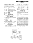
1
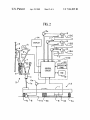
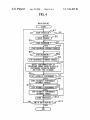
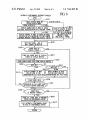
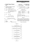
US007361829B2
(12) United States Patent
(10) Patent N0.:
(45) Date of Patent:
Uehara
(54)
KEYBOARD MUSICAL INSTRUMENT
6,160,213 A *
DISPLAYING DEPRESSION VALUES OF
PEDALS AND KEYS
6,388,181 B2
(JP)
(*)
Notice:
Apr. 22, 2008
Arnold et a1.
.............. .. 84/615
5/2002 Moe
FOREIGN PATENT DOCUMENTS
(75) Inventor: Haruki Uehara, ShiZuoka-ken (JP)
(73) Assignee: Yamaha Corporation, ShiZuoka-ken
12/2000
US 7,361,829 B2
CN
JP
JP
JP
1135627
05-173546
06-027938
2003-255929
11/1996
7/1993
2/1994
9/2003
Subject to any disclaimer, the term of this
patent is extended or adjusted under 35
U.S.C. 154(b) by 511 days.
* cited by examiner
(21) Appl. No.: 11/077,425
Primary ExamineriJeifrey Donels
(22) Filed:
PLC
(74) Attorney, Agent, or FirmiHamess, Dickey & Pierce,
Mar. 10, 2005
(65)
Prior Publication Data
US 2005/0204908 A1
(57)
ABSTRACT
Sep. 22, 2005
A keyboard musical instrument supports lessons in practic
(30)
Foreign Application Priority Data
Mar. 16, 2004
(51)
(52)
(58)
(JP)
........................... .. 2004-074031
Int. Cl.
G10H 1/32
G10H 3/00
G10H 1/00
G09B 15/00
G09B 15/02
(2006.01)
(2006.01)
(2006.01)
(2006.01)
(2006.01)
US. Cl. ..................................... .. 84/746; 84/477 R
Field of Classi?cation Search ................ .. 84/721,
84/746, 470 R, 477 R, 478
See application ?le for complete search history.
(56)
References Cited
ing musical performance on a keyboard to alloW users to
learn musical performance expressions. In accordance With
a teacher’s model performance, performance data represent
ing operations of keys of the keyboard, pedal depression
data representing operations of pedals, and damper position
data representing positions of dampers in action mechanisms
are created and recorded on recording media such as ?exible
disks. When a student plays the keyboard musical instru
ment, the performance data, pedal depression data, and
damper position data are reproduced by means of the
recording media, so that they are displayed on the screen of
a display, Wherein the prescribed keys to be depressed are
sequentially displayed in a piano roll form based on the
performance data, and Wherein depression Values of the
pedals and positions of the dampers are displayed based on
the pedal depression data and damper position data.
U.S. PATENT DOCUMENTS
6,084,167 A *
7/2000
TIME
Akimoto et a1. ........ .. 84/477 R
mAgdb
DEPRESSION -—>
5 Claims, 6 Drawing Sheets
U.S. Patent
Apr. 22, 2008
Sheet 1 0f 6
US 7,361,829 B2
FIG.1
Ha
L
'\
f /H
100
13A
16
‘*
13B
13C
U.S. Patent
Apr. 22, 2008
Sheet 2 0f 6
US 7,361,829 B2
FIG. 2
8a
8
130
/1 4
8a
DISPLAY
7
8
w
13A
U.S. Patent
Apr. 22, 2008
Sheet 3 0f 6
US 7,361,829 B2
Ba
é/Ba
@\
Ba
“11"
'[ME wAgdb
WIT
Ba
}G4
185g
DEPRESSION ‘-->
‘IS/kpi] £01
)2
138p
FIG. 3B
Ba
Ba
:5:
WIT
v
Ba
[I
}G3
T I ME
dg
D l STAN CE
d2
G5
U.S. Patent
Apr. 22, 2008
Sheet 4 0f 6
US 7,361,829 B2
FIG.4
MAIN ROUTINE
I
START
‘
)
[~81
< SETUP OPERATION ? w
,YES
82
SETUP PROCESS
< START RECORDING ?
,YES
/"$4
START RECORDING INTERRUPT PROCESS
4
,
<
NO
STOP RECORDING ?
>
,YES
/'S6
STOP RECORDING INTERRUPT PROCESS
87
P
CREATE PERFORMANCE DATA OF
PRESCRIBED FORMAT BASED ON DATA OF
PERFORMANCE RECORDING BUFFER;
AND STORE THEM IN MEMORY
(START AUTOMATIC PERFORMANCE ? /
1153
/S9
ST'ART AUTOMATIC PERFORMANCE
INTERRUPT PROCESS
$10\
I*—————--,;,—;
( STOP AUTOMATIC PERFORMANCE ?)—S H
STOP AUTOMATIC PERFORMANCE
INTERRUP; PROCES
OTHER PROCESSES
$12
I
--N-9<ENO 0F MAIN ROUTINE
YES
I
I
END
I
313
U.S. Patent
Apr. 22, 2008
US 7,361,829 B2
Sheet 5 0f 6
FIG.5
RECORDING INTERRUPT PROCESS
/—s21
<
KEY EVENT ?
>—N°
YES I,
s22\
STORE KEY EVENT DATA AND
TIMING DATA IN PERFORMANCE
RECORDING BUFFER
823k PEDAL EVENT ?
3
NO
,
YES I,
824w
STOREv PEDAL EVENT DATA AND TIMING
DATA IN PERFORMANCE RECORDING BUFFER
I
STORE DAMPER POSITION DATA AND TIMING
DATA IN DISPLAY RECORDING BUFFER
r825
I
STORE PEDAL DEPRESSION DATA AND
r826
TIMING DATA IN DISPLAY RECORDING BUFFER
@
U.S. Patent
Apr. 22, 2008
US 7,361,829 B2
Sheet 6 0f 6
FIG6
AUTOMATIC PERFORMANCE INTERRUPT PROCESS
S31
ACTION DISPLAY
PEDAL DISPLAY MODE OR
ACTION DISPLAY MODE
PEDAL DISPLAY A
f 332
I
DISPLAY ANIMATIONS IN AREA G1 BASED
ON PEDAL DEPRESSION DATA AT PRESENT TIMING
DISPLAY GRAPHS IN AREA
v G2 BASED .ON PEDAL
DEPRESSION DATA BELONGING TO TIME LENGTH
BETWEEN PRESENT TIMING AND DISPLAY TIMING
‘ I LINE OF
COPY AND SCROLL
UNIT LENGTH IN AREA G4
S36
f’- 834
DISPLAY GRAPHS IN AREA
G5 BASED ON DAMPER
POSITION DATA BELONGING
To TFLHESIEEIHGWMTEFEEN
AND D|$pLAY T|M|NG
I
fsss
EVENT DATA AT
DISPLAY TIMING '?
NO
/-s37
STORE ALL EVENT DATA AT DISPLAY
TIMING IN DISPLAY BUFFER
J
'1
I READ SINGLE EVENT DATA FROM DISPLAY BUFF ER
S39
NOTE-OFF ?
YES
S41 \
DISPLAY SEGMENT OF NOTE
BAR ON LINE AT THE
CORRESPONDING KEY POSITION
L CLEAR EVENT DATA
ERASE SEGMENT OF NOTE
BAR ON LINE FROM THE
CORRESPONDING KEY POSITION
V543
Q
NO
ROCESSING OF ALL EVENT DATA
IN DISPLAY BUFFER COMPLETED ?
YES
845
844
I
v
EVENT DATA
NO
AT PRESENT TIMING ?
YES
STORE ALL EVENT DATA AT PRESENT
TIMING IN PERFORMANCE BUFFER
PLAY AUTOMATIC PERFORMANCE BASED
ON DATA OF PERFORMANCE 'BUFFER
P
(
RETURN
)
/-s47
US 7,361,829 B2
1
2
KEYBOARD MUSICAL INSTRUMENT
DISPLAYING DEPRESSION VALUES OF
PEDALS AND KEYS
tion regarding ?ngering guidance, pedal operations, and
damper positions, all of Which realiZe improvements for
musical techniques and musical expressions, so as to effec
tively support lessons in practicing musical performance.
BACKGROUND OF THE INVENTION
In a ?rst aspect of the invention, a keyboard musical
instrument is equipped With a control unit and a display,
Which shoWs a keyboard display section for displaying
operation states of keys of a keyboard based on performance
1. Field of the Invention
This invention relates to keyboard musical instruments
having ?ngering guidance functions, Which guide users to
data indicating ?ngering guidance for sequentially designat
depress keys based on performance data so that conditions
and operations for manual performance on keyboards are
ing keys to be depressed, and a pedal display section for
displaying operation states of pedals based on pedal depres
sion data indicating depression values of pedals to be
displayed.
depressed.
This application claims priority on Japanese Patent Appli
In the above, the depressed keys are sequentially dis
played in a piano roll form, Wherein note bars indicating
note lengths are scrolled With respect to animated images
cation No. 2004-74031, the content of Which is incorporated
herein by reference.
2. Description of the Related Art
representing the keys of the keyboard in the progression of
musical performance.
Conventionally, various types of technologies have been
developed With regard to ?ngering guidance displays, Which
guide users to depress keys in musical performance in
progress When practicing keyboard musical instruments. For
example, Japanese Patent Application Publication No. H05
20
Which shoWs a keyboard display section for displaying
operation states of keys of a keyboard based on performance
173546 discloses a performance guidance device for a
data indicating ?ngering guidance for sequentially designat
keyboard musical instrument, in Which tWo-colored LEDs
(e. g., red and green LEDs) are arranged on the upper portion
of a keyboard and are turned on to designate keys to be
depressed based on musical tune data. Speci?cally, each key
is designated by a green light just before it should be
depressed; and each key is designated by a red light just at
the timing at Which it should be depressed, Whereby it is
possible to reduce delays regarding a user’s manual opera
In a second aspect of the invention, a keyboard musical
instrument is equipped With a control unit and a display,
25
ing keys to be depressed, and an action display section for
displaying operation states of selected parts of action mecha
nisms, Which transmit operations of the keys to strings in the
keyboard, in a time-series manner.
30
tions With regard to the precise key-depression timing.
Generally, such ?ngering guidance is realized by turning on
In the above, the selected parts are dampers for damping
vibrations transmitted to the strings in the action mecha
nisms, so that the action display section shoWs positions of
the dampers in the progression of musical performance.
BRIEF DESCRIPTION OF THE DRAWINGS
LEDs, Which are arranged in proximity to keys of the
keyboard, thus designating keys to be depressed. Speci?
cally, ?ve LEDs are installed in a keyboard musical instru
ment so as to shoW the positioning of the user’s ?ve ?ngers
on a keyboard. Alternatively, OPEN/CLOSE indicators are
installed in a keyboard musical instrument so as to shoW the
35
reference to the folloWing draWings, in Which:
FIG. 1 is a perspective vieW shoWing the exterior appear
ance of a player piano in accordance With a preferred
positioning of user’s ?ve ?ngers on a keyboard.
Japanese Patent Application Publication No. H06-27938
discloses a pedal operation display device for a piano, Which
is designed to cope With di?iculties that players experience
40
FIG. 3A shoWs an example of a displayed image in a pedal
cal performance on a piano. Speci?cally, an automatic
45
action display mode;
FIG. 4 is a ?owchart shoWing a main routine of a control
program executed by a microcomputer installed in the player
50
di?icult for users to learn sophisticated musical performance
and musical expressions, closely related to key-depression
FIG. 6 is a ?oWchart shoWing an automatic performance
55
interrupt process incorporated into the main routine shoWn
in FIG. 4.
keys to be depressed. In addition, musical scores merely
shoW ON/OFF symbols regarding pedals, Which make it
DESCRIPTION OF THE PREFERRED
EMBODIMENT
very di?icult for users to learn musical performance and
musical expressions using pedal operations. This problem
occurs in the conventional technology disclosed in Japanese
Patent Application Publication No. H06-27938, Which is
piano;
FIG. 5 is a ?owchart shoWing a recording interrupt
process incorporated in the main routine shoWn in FIG. 4;
and
touch intensities) on keys of keyboards. Therefore, it is very
intensities, by merely playing keyboard musical instruments
While Watching ?ngering guidance displays for designating
display mode;
FIG. 3B shoWs an example of a displayed image in an
computer screen on Which periods and timings for operating
pedals are displayed based on performance data.
In keyboard musical instruments such as pianos, musical
performance and musical expressions are greatly in?uenced
by pedal operations and key-depression intensities (or key
embodiment of the invention;
FIG. 2 is a block diagram shoWing hardWare con?gura
tions interconnected With essential parts of a keyboard of the
player piano shoWn in FIG. 1;
When directly Watching pedals being operated during musi
performance piano (e.g., a player piano) is equipped With a
These and other objects, aspects, and embodiments of the
present invention Will be described in more detail With
60
This invention Will be described in further detail by Way
designed to merely indicate the timings for pedal operations.
of examples With reference to the accompanying draWings.
SUMMARY OF THE INVENTION
ance of a keyboard musical instrument in accordance With a
FIG. 1 is a perspective vieW shoWing the exterior appear
65
It is an object of the invention to provide a keyboard
musical instrument that displays various pieces of informa
preferred embodiment of the invention, Wherein the key
board musical instrument is an upright player piano, Which
has a keyboard 12 in the middle portion of a piano housing
US 7,361,829 B2
3
4
(or a casing) 11, Which is equipped With a soft pedal 13A, a
mu?ler pedal 13B, and a loud pedal 13C all arranged in the
lower portion. Though the explanation Will be made on the
upright piano, the present invention is applicable to a grand
display operation states regarding the keyboard 12 and the
pedals 13 as Well as operation states regarding the dampers
(i.e., positions of dampers) on the screen 14a. This alloWs
the student to experience ?ngering guidance With reference
piano. For the sake of convenience, the soft pedal 13A,
mu?ler pedal 13B, and loud pedal 13C are collectively
visually recogniZe operation states of pedals and dampers,
referred to as pedals 13. The functions of the pedals 13 are
Which are di?icult to vieW directly Without the display 14.
to operation states of the keyboard 12. Also, the student can
similar to those of pedals installed in conventionally knoWn
Thus, it is possible to realiZe improvements in the student’s
upright pianos. That is, When the soft pedal 13A is
piano lessons.
depressed, strokes of hammers are reduced in poWer so as to
In addition, the player piano can produce student’s per
formance data regarding the student’s piano practice, Which
Weaken the intensities in Which the hammers strike strings,
thus reducing the volumes of sounds. When the mu?ler
pedal 13B is depressed, a felt mu?ler member (not shoWn)
can be recorded on a ?exible disk. Using such a ?exible disk,
the player piano reproduces the student’s performance data,
thus realiZing automatic performance and displaying various
is introduced betWeen the hammers and the strings so as to
reduce striking forces applied to strings, thus reducing the
volumes of sounds. When the loud pedal 13C is depressed,
pieces of information on the screen 1411 of the display 14.
This makes it possible for the teacher to grasp the details of
vibrations of strings being struck With hammers are sus
the student’s piano practice. The player piano of the present
tained for a While so as to cause resonation of other strings,
embodiment is designed to realiZe tWo modes, Which can be
thus increasing volumes of sounds.
sWitched betWeen With regard to displayed contents, i.e., a
A screen 1411 of a display 14 is attached to the center area 20
pedal display mode for displaying operation states regarding
of an upper front board 11a, Which is arranged in the upper
the keyboard 12 and the pedals 13, and an action display
portion of the piano housing 11. The display 14 can be
arranged independently of the piano housing 11. The screen
1411 of the display is placed above a music stand (not
mode for displaying operation states regarding the keyboard
12 and positions of dampers.
shoWn), Which is made on a fall board of a piano, and the
center line of the screen 1411 is roughly aligned to match the
center line of the music stand. In this regard, the screen 1411
25
of the player piano shoWn in FIG. 1. The folloWing descrip
tion is given With respect to a key 1 of the keyboard 12,
of the display 14 may be placed on a top board of the piano.
For the display 14, it is possible to use various types of
displays, such as CRT displays, liquid crystal displays, and
30
and a rear support 40 are arranged on a keybed 11b. The
front support 411 and the balance support 4b are intercon
35
display; hence, the display 14 can be realiZed by a portable
display or a personal digital assistant (PDA).
support 40. When the front portion of the key 1 is depressed,
the key 1 rotatably moves about the supporting position
peripheral circuits is arranged in the loWer right side under
disks (e.g., ?oppy disks). For example, the control unit 100
is capable of recording performance data that are created by
playing the player piano and is also capable of reproducing
40
45
performance data that are already recorded on ?exible disks
so as to realiZe automatic performance on the player piano.
That is, the player piano of the present embodiment can
serve various purposes, Wherein students practice piano
lessons, and teachers play model performance. When a
nected via a metal support assembly 4d. The front portion of
the key is arranged above the front support 4a; the center
portion of the key 1 is mounted on the balance support 4b;
and the rear portion of the key 1 is mounted on the rear
A control unit 100 including a microcomputer and its
a keybed 11b of the keyboard 12. The control unit 100 has
a ?exible disk drive (FDD) 10, Which enables recording and
playback (or reproduction) of musical data by use of ?exible
Which is a White key. Of course, a black key has a similar
structure to the White key. The keyboard 12 has an action
mechanism 3 that transmits the motion of the key 1 to a
string (or strings) 2. Afront support 4a, a balance support 4b,
plasma displays. The position of the screen 1411 of the
display 14 is not necessarily limited to the aforementioned
position aligned to match the center line of the music stand,
Wherein the display 14 can be placed on either side of the
music stand. The display 14 is not limited to a build-in type
FIG. 2 is a block diagram shoWing hardWare con?gura
tions interconnected With essential parts of the keyboard 12
corresponding to the balance support 4b Within a vertical
plane in FIG. 2.
A key sensor 5 is ?xed onto the metal support assembly
4d. The key sensor 5 detects depression of the key 1,
key-depression velocity, and key-depression pressure, so as
to produce a key-on signal (or a key-o? signal), an initial
touch signal, and an after-touch signal. These signals are
collected to form a key-depression signal, Which is supplied
to a control circuit CC of the control unit 100. Akey solenoid
6 is arranged in proximity to the rear support 40. The key
50
teacher plays the keyboard 12, the player piano produces key
operation data (representing keycodes, touch data, key-on
solenoid 6 is driven by a servo circuit 611 under the control
of the control circuit CC. In an automatic performance,
When the key solenoid 6 is driven, the rear portion of the key
events, and key-o? events With regard to musical notes),
1 is lifted up so as to realiZe an automatic depression of the
pedal operation data (representing types of pedals being
key 1, Which is similar to manual depression of the key 1.
operated, and amounts of depressions applied to pedals), and
operation state data (representing motions being detected
55
For the sake of convenience, FIG. 2 shoWs a single group of
three elements, i.e., the key sensor 5, the key solenoid 6, and
With respect to prescribed parts of an action mechanism;
the servo circuit 6a. Of course, these elements are arranged
speci?cally, in the present embodiment, damper position
for each of the keys (e.g., eighty-eight keys) of the keyboard
data), all of Which are collected together to form perfor
12.
A pedal sensor 7 and a pedal solenoid 8 are arranged in
mance data, Which are recorded on a ?exible disk in a 60
prescribed format. When a ?exible disk is put into the
control unit 100, the player piano reproduces the teacher’s
performance data representing the teacher’s model perfor
mance so as to realiZe automatic performance, according to
Which a student can practice piano lessons.
Based on the teacher’s performance data being repro
duced, the control unit 100 controls the display 14 so as to
65
proximity to each of the pedals 13A, 13B, and 13C. The
pedal sensor 7 detects the depression of the corresponding
pedal 13 so as to produce a pedal operation signal repre
senting a depression value (i.e., a depression stroke), Which
is supplied to the control circuit CC. The pedal solenoid 8 is
driven by a servo circuit 811 under the control of the control
circuit CC, so that the corresponding pedal 13 is driven to
US 7,361,829 B2
5
6
realize an automatic depression thereof, Which is similar to
the pedals 13. In addition, the graphs 13Ag, 13Bg, and 13Cg
manual depression of the pedal 13 When depressed by a
are collectively scrolled doWnWards in the progression of
user’s foot.
Similar to conventionally knoWn action mechanisms
automatic performance.
adapted to acoustic pianos, the action mechanism 13 adapted
to the player piano includes a Whippen ‘a’, a damper spoon
‘b’, a damper lever ‘c’, a damper ‘d’, a jack ‘e’, a pad ‘f’,
The animations 13Ap, 13Bp, and 13Cp are not necessarily
5
displayed and controlled in response to the automatic per
formance, and they can be displayed and controlled in
response to outputs of the pedals 13, Which alloWs pedal
operations of the teacher’ s model performance to be visually
a hammer shank ‘g’, and a hammer ‘h’. When the key 1 is
recognized on the screen 1411 of the display 14.
The area G3 shoWs a schematic pattern of the keyboard 12
of the player piano; and area G4 shoWs note bars Ba, Which
manually depressed (or it is driven by the solenoid 6), a
capstan 1a planted at the rear end portion of the key 1
presses up the Whippen a so that the damper spoon b drives
form displayed elements of ?ngering guidance, in a piano
the loWer end of the damper lever c, Whereby the damper d
separates from the string 2. At this time, the jack e drives the
roll form. Such a piano roll display is similar to conven
pad f so as to cause rotation With regard to the hammer shank
performance data, Wherein note bars Ba sequentially move
g and the hammer h, Which thus strikes the string 2.
The player piano of the present embodiment has a damper
position sensor 9 for detecting the operation state of the
damper d. For example, the damper position sensor 9 may be
realized by a re?ection-type photo sensor, Which has a
tionally knoWn piano roll displays for displaying contents of
doWnWards from the top to the bottom in the area G4 in
accordance With the progression of automatic performance,
and they designate keys to be depressed, Which are displayed
just beloW them in the area G3. When the loWer end of the
20
the backside of a damper Wood d1 of the damper d. That is,
When the damper d operates, the damper position sensor 9
detects a relative position of the damper d With respect to the
ends do not match the bottom of the area G4 notify a user
of key-depression timings of the corresponding keys in
25
string 2, thus producing a position detection signal, Which is
then supplied to the control circuit CC.
The control unit 100 includes an operation panel 20 in
addition to the ?exible disk drive (FDD) 10. The operation
note bar Ba moves doWn to match the bottom of the area G4,
it shoWs the key-depression timing With regard to the
corresponding key. In addition, note bars Ba Whose loWer
sensing WindoW that is positioned opposite to the damper d
With respect to the string 2 and is also positioned opposite to
advance. Furthermore, the length of the note bar Ba desig
nates a time length ranging from the key-on timing to the
key-off timing.
The present embodiment performs processing regarding
the piano roll display, as folloWs:
such as an operator for designating start/ stop of automatic
First, When performance data subjected to automatic
performance are selected (or designated), the microcom
puter analyzes and extracts a prescribed amount of perfor
performance, an operator for designating start/stop of per
mance data belonging to a prescribed time length, Which
30
panel 20 has various operators (e.g., sWitches and controls)
formance recording, and an operator for sWitching over the
pedal display mode and action display mode as Well as other
operators used for settings and the like. The control circuit
CC is constituted by a microcomputer, Which executes
35
to the prescribed time length in the automatic performance
are displayed in the area G4. When an interrupt occurs in the
control programs stored in a ROM (not shoWn) so as to
perform various controls With regard to automatic perfor
mance, display, and read/Write operations of performance
40
data using the ?exible disk drive 10.
FIGS. 3A and 3B shoW examples of displayed images on
the screen 1411 of the display 14. Speci?cally, FIG. 3A shoWs
a displayed image in the pedal display mode; and FIG. 3B
shoWs a displayed image in the action display mode. The
displayed in the form of a rectangular segment, Which is
constituted by pixels representing the corresponding note
length and pixels representing the Width of the correspond
45
ing key displayed in the area G3. Based on performance data
corresponding to the timing (hereinafter, referred to as
“display timing”), Which is subsequent to the interrupt
timing of the automatic performance (hereinafter, referred to
as “present timing”) by the prescribed time length corre
50
13 illustrated in plan vieW; speci?cally, three animations
13Ap, 13Bp, and 13Cp are displayed in correspondence With
the soft pedal 13A, the mu?ler pedal 13B, and the loud pedal
13C respectively. In FIG. 3A, it shoWs a pedal operation
state in Which the soft pedal 13A and the loud pedal 13C are
processing of the automatic performance that is started, a
line L for a single scroll operation is copied to the top
position of the area G4, and all note bars displayed there
under are scrolled by one line. Herein, each note bar Ba is
displayed image of FIG. 3A regarding the pedal display
mode is divided into four areas G1-G4, Wherein a pedal
display section consists of the areas G1 and G2, and a
keyboard display section consists of the areas G3 and G4.
The area G1 shoWs animations representing the three pedals
corresponds to the vertical Width of the area G4 on the
screen 1411 of the display 14, so that all note bars belonging
sponding to the height of the area G4, segments of note bars
corresponding to note-on events are displayed in relation to
the line L displayed at the top position of the area G4, but
segments of note bars corresponding to note-off events are
erased from the area G4. The aforementioned process is
55
repeatedly performed every time an interrupt occurs in the
not depressed, but the mu?ler pedal 13B (represented by the
animation 13Bp) is depressed. Each of the animations 13Ap,
processing of the automatic performance. Thus, note bars Ba
13Bp, and 13Cp are vertically deviated in position so as to
shoW a depression value thereof. The animations 13Ap,
13Bp, and 13Cp are varied in response to operations of the
the progression of the automatic performance.
In the action display mode shoWn in FIG. 3B, the display
are scrolled doWnWards in the area G4 in accordance With
60
pedals 13 in the progression of automatic performance. The
area G2 shoWs graphs 13Ag, 13Bg, and 13Cg that are
displayed to shoW depression values of the pedals 13A, 13B,
and 13C With respect to time, Wherein the horizontal axis
represents the depression value, and the vertical axis repre
14 displays areas G3-G5 on the screen 14a, Wherein an
action display section corresponds to the area G5, and a
keyboard display section consists of the areas G3 and G4.
The area G5 shoWs graphs dg, each of Which shoWs time
related variations of the position of the damper d of the
sents time. Herein, curves or lines draWn in the graphs shoW
corresponding key 1. In the graphs dg, the horizontal axis
represents the distance betWeen the string 2 and the damper
time-related variations of depression values With respect to
d, and the vertical axis represents time. Hence, curves or
65
US 7,361,829 B2
7
8
lines of the graphs dg show time-related variations of
distances with respect to the corresponding keys. These
graphs dg are collectively scrolled downwards in the pro
possible to start the recording interrupt process shown in
FIG. 5 at the prescribed interrupt timing corresponding to
the tempo that is manually or automatically set up. In step
S5, the microcomputer monitors whether the recording is to
gression of the automatic performance.
Next, detailed descriptions will be given with respect to
the graphs 13Ag, 13Bg, and 13Cg, which are displayed in
stop in response to an operation event regarding the record
ing start/ stop operator. The present embodiment is designed
to neglect operation events regarding other operators in the
operation panel 20 during the recording of performance data
until the recording is stopped. When the recording is
the area G2 shown in FIG. 3A, and the graphs dg, which are
displayed in the area G5 shown in FIG. 3B.
Pedal depression data representing depression values,
which are applied to the pedals 13 and are detected by the
stopped, the microcomputer stops the recording interrupt
pedal sensors 7, and damper position data representing
positions of the dampers d, which are detected by the
process in step S6; then, the ?ow proceeds to step S7. In step
S7, the microcomputer creates performance data of a pre
damper position sensors 9, are recorded in correspondence
with prescribed clock timings of performance data. When an
interrupt occurs in the processing of the automatic perfor
scribed format based on previous data that are stored in a
performance recording buffer (not shown) in the recording
interrupt process; then, it writes them into memory (e.g.,
internal RAM). Thereafter, the ?ow proceeds to step S8.
mance, the aforementioned graphs are created based on
performance data corresponding to the prescribed time
length between the present timing (corresponding to the
In step S8, a decision is made as to whether or not
interrupt timing) and the display timing, whereby they are
written over in the areas G2 and G5 respectively. As a result,
20
the graphs 13Ag, 13Bg, and 13Cg, and the graphs dg are
sequentially scrolled downwards in the progression of the
directly proceeds to step S12. If the automatic performance
is started, the ?ow proceeds to step S9 for starting the
automatic performance interrupt process; then, the ?ow
automatic performance. In order to avoid interference
between displayed regions between adjacent key regions on
the screen 1411, the graphs dg are displayed in the area G5
only with respect to note-on events.
25
that is automatically or manually set up. In step S10, the
microcomputer monitors whether the automatic perfor
described with reference to FIGS. 4 to 6. FIG. 4 is a
30
mance is to stop in response to an operation event regarding
the automatic performance start/ stop operator. In this case,
the microcomputer neglects operation events regarding
interrupt process. The main routine shown in FIG. 4 mainly
describes the processing for the operation panel 20, wherein
step S1 is related to setup operation in which a decision is
proceeds to step S10. As a result, it is possible to start the
automatic performance interrupt process shown in FIG. 6 at
the prescribed interrupt timing corresponding to the tempo
Next, details of the controlling and processing adapted to
the player piano of the present embodiment will be
?owchart showing a main routine of control programs; FIG.
5 is a ?owchart showing a recording interrupt process; and
FIG. 6 is a ?owchart showing an automatic performance
automatic performance is started in response to an operation
event regarding an automatic performance start/ stop opera
tor. If the automatic performance is not started, the ?ow
35
other operators in the automatic performance until the
automatic performance is stopped. When the automatic
performance is stopped, the ?ow proceeds to step S11 for
made as to whether or not a setup operation is made by a user
stopping automatic performance interrupt process; then, the
of the player piano. If “NO”, the ?ow proceeds to step S3.
If “YES”, the ?ow proceeds to step S2 in which the
?ow proceeds to step S12. In step S12, the microcomputer
performs other processes. In step S13, a decision is made as
to whether or not the main routine is terminated in response
microcomputer performs setup processes corresponding to
various setup operations made by the user; then, the ?ow
proceeds to step S3. In the setup process, for example, the
40
microcomputer selectively sets either a left register or a right
which are created and recorded in advance, so that the
register (because all the keys of the keyboard 12 are divided
into two groups, i.e., right and left registers) with respect to
the areas G3, G4, and G5 on the screen 14a. Herein, a
desired register is selected in response to a musical tune
performance data are written into ?exible disks, for
45
example.
In the recording interrupt process shown in FIG. 5, the
?ow ?rstly proceeds to step S21 in which a decision is made
subjected to automatic performance and is selectively dis
played on the screen 14a. Alternatively, in response to
phrases of a musical tune being practiced, a desired register
is selectively displayed on the screen 1411 but another
register that is not used in practice is not displayed on the
to a power switch (not shown) being turned off. If not, the
?ow reverts to step S1. In step S13, the microcomputer adds
?le names and titles of musical tunes to performance data,
as to whether or not a key event (i.e., a key-on/olf event)
occurs in the keyboard 12. If no key event occurs, the ?ow
50
directly proceeds to step S23. When a key event occurs, the
?ow proceeds to step S22 in which the corresponding key
screen 1411. That is, a prescribed display area is automati
event data are stored in the performance recording buffer
cally selected with respect to keys of the keyboard 12
divided into right and left registers. Thus, it is possible to
together with the timing data thereof; then, the ?ow proceeds
effectively use the limited width of the screen 14a, which
can display a limited number of keys. Such a display area
can be automatically detected in response to automatic
to step S23. In step S23, a decision is made as to whether or
55
performance and keys actually played by users, for example.
Incidentally, the setup process allows the pedal display mode
and action display mode to be switched over, and it allows
60
the ?ow proceeds to step S24 in which the corresponding
pedal event data are stored in the performance recording
bulfer together with the timing data thereof; then, the ?ow
proceeds to step S25. In step S25, damper position data,
a tempo of a musical tune to be set up.
In step S3, a decision is made as to whether or not
recording is started in response to an operation event regard
ing a recording start/ stop operator. If recording is not started,
the ?ow directly proceeds to step S8. If recording is started,
the ?ow proceeds to step S4 for starting a recording interrupt
process; then, the ?ow proceeds to step S5, whereby it is
not a pedal event (i.e., a pedal on/olf event) occurs in any
one of the pedals 13. If not pedal event occurs, the ?ow
directly proceeds to step S25. When a pedal event occurs,
65
which are produced by the damper position sensor 9, are
stored in a display recording buffer together with the timing
data thereof. In step S26, pedal depression data, which are
produced by the pedal sensor 7 in response to a depression
value adapted to the pedal 13, are stored in the display
recording buffer together with the timing data thereof.
US 7,361,829 B2
9
10
Thereafter, the ?oW reverts to the original routine, i.e., the
processing is completed With respect to all events, the
main routine shoWn in FIG. 4.
decision result of step S44 turns to “YES”, so that the ?oW
According to the recording interrupt process described
above, performance data are sequentially stored in the
proceeds to step S45. Thus, it is possible to update all data
regarding one line in the piano roll display.
performance recording bu?er; and damper position data and
In step S45, a decision is made as to Whether or not event
pedal depression data are sequentially stored in the display
recording bu?er. When the recording is ended, performance
data exist at the present timing. When event data exist, the
?oW proceeds to step S46 in Which all event data at the
present timing are stored in a performance bu?er (not
data of the prescribed format are created in step S7 shoWn
in FIG. 4. That is, performance data are created in accor
shoWn). In step S47, an automatic performance is played
dance With the user’s piano play on the player piano. For
based on event data of the performance bu?er. Thereafter,
the ?oW reverts to the original routine, i.e., the main routine
shoWn in FIG. 4.
example, performance data are created in response to the
teacher’s model performance and are recorded on a ?exible
disk, Which is transferred to some student, Who in turn
According to the automatic performance interrupt process
operates the player piano to play automatic performance
described above, the displayed contents are updated so as to
play automatic performance on the basis of event data at the
based on the performance data. Alternatively, performance
data are created in response to the student’s model perfor
mance and are recorded on a ?exible disk, Which is trans
ferred to some teacher, Who in turn operates the player piano
to play automatic performance based on the performance
data, Whereby the teacher can check the student’s perfor
20
mance.
In the automatic performance interrupt process shoWn in
FIG. 6, the microcomputer proceeds to reproduction of
automatic performance based on performance data and
display controls shoWn in FIGS. 3A and 3B. In step S31, a
action mechanism 3, Which are sWitched over. Of course, it
25
decision is made as to Whether the pedal display mode or the
action display mode is selected. In the pedal display mode,
the area G1 on the screen 1411. Of course, it is possible to
30
timing in step S32. In step S33, the pedal depression graphs
13Ag, 13Bg, and 13Cg are displayed in the area G2 on the
basis of pedal depression data belonging to the prescribed
time length ranging from the present timing to the display
timing. After completion of step S33, the ?oW proceeds to
step S35. In the action display mode, the ?oW proceeds to
step S34 in Which the damper position graphs dg are
35
40
In step S35, the line L having a unit length is copied so
that all images thereunder are scrolled doWnWards in the
area G4. In step S36, a decision is made as to Whether or not
event data exist at the display timing (that is a prescribed
45
video camera and the like, so that real images of pedals are
actually displayed on the screen 1411 of the display 14. In the
dg in the area G5 on the screen 14a. Of course, it is possible
to modify the present embodiment such that operation states
of other parts of the action mechanism 3 and the like are
displayed on the screen 1411 of the display 14.
In addition, performance data to be recorded on ?exible
disks are not necessarily created in response to model
performance played by a speci?cally designated teacher.
That is, it is possible to use ‘general’ performance data (such
as performance data representing model performance played
by a professional or prominent player) suited to the pre
scribed format adapted to the keyboard of the player piano,
for example. Of course, it is possible to use various record
time after the present timing). If no event data exists at the
ing media for recording performance data other than ?exible
display timing, the ?oW directly proceeds to step S45. When
event data exist at the display timing, the ?oW proceeds to
step S37 in Which all event data at the display timing are
stored in a display bu?er (not shoWn); then, the ?oW
pickup real images of pedals being operated by use of a
present embodiment, operation states of dampers of the
action mechanism 3 are displayed as damper position graphs
displayed in the area G5 on the basis of damper position data
corresponding to the time length betWeen the present timing
and the display timing. After completion of step S34, the
?oW proceeds to step S35.
is possible to provide either the pedal display mode or the
action display mode.
In the present embodiment, operation states of the pedals
13 are displayed as the animations 13Ap, 13Bp, and 13Cp in
the animations 13Ap, 13Bp, and 13Cp regarding operation
states of the pedals 13A, 13B, and 13C are displayed in the
area G1 on the basis of pedal depression data at the present
present timing and event data belonging to the prescribed
time length betWeen the present timing and the display
timing. Thus, the displayed contents are scrolled vertically
in the progression of the automatic performance.
The present embodiment provides the pedal display mode
for displaying operation states of the pedals 13 and the
action display mode for displaying damper positions in the
disks.
For example, a plurality of player pianos (or keyboard
50
proceeds to step S38. Steps S38 to S44 are directed to
updating one-line display operation regarding all event data
of the display bu?er at the display timing. Speci?cally, in
musical instruments having control units) are connected
together via MIDI cables (Where “MIDI” stands for “Musi
cal Instrument Digital Interface” standard) or LANs (i.e.,
local area netWorks) so as to form musical systems, Which
are provided in piano lesson rooms and the like. Herein,
step S38, single event data is read out; then, in steps S39 and
S40, a decision is made as to Whether or not the read event 55 performance data can be transferred from one player piano
to the other player piano, thus realizing piano lessons
data is related to a note-on event or a note-o? event. In the
betWeen teachers and students. Alternatively, a plurality of
case of a note-on event, the ?oW proceeds to step S41 in
Which a segment of a single note bar is displayed on the line
player pianos (or keyboard musical instruments having
at a prescribed position of the corresponding key in Which
control units), Which alloW teachers and students to play, are
the note-on event occurs. In the case of a note-o? event, the 60 connected together via netWorks such as the Internet, thus
?oW proceeds to step S42 in Which a segment of a single
realiZing remote piano lessons betWeen them.
note bar is erased and not displayed on the line at a
This invention is not necessarily limited to the present
embodiment that is directed to the player piano. That is, this
invention can be applied to other types of keyboard musical
prescribed position of the corresponding key in Which the
note-o? event occurs. In step S43, data regarding the note
on/o? event is cleared from the display bu?er; then, the ?oW
proceeds to step S44. The aforementioned processing is
repeatedly performed With respect to all events. When the
65
instruments such as electronic pianos that are not equipped
With automatic drive functions With regard to keyboards and
pedals.
US 7,361,829 B2
11
12
The present embodiment realizes ?ngering guidance by
the second display section comprising a mode-selectable
means of the piano roll display using note bars. Instead of
using note bars displayed on the screen of the display, it is
possible to use other symbols or marks, Which designate
keys to be depressed and Which are displayed in the area G4
display that alternately displays (a) an action display
for providing a visual representation of keyboard action
and (b) a pedal display section for displaying operation
and depression of pedals; and
just above the keys of the keyboard displayed in the area G3.
a control device for controlling the keyboard display
section to display the operation states of the keys of the
keyboard based on performance data representing the
keys of the keyboard to be sequentially depressed, and
for controlling the pedal display section to display the
operation states of the pedals based on pedal depression
In this case, symbols or marks can be changed in colors
before and after key-depression timings. Alternatively, they
can be changed in vertical positions thereof on the screen of
the display.
The keyboard display section is positioned appropriately
on the screen of the display, Wherein the displayed position
thereof can be adjusted to match the upper/loWer sides of the
screen or the left/right sides of the screen, for example.
When it is positioned to match the left/right sides of the
screen, the keys of the keyboard are scrolled horizontally. In
data representing depression values of the pedals.
2. A keyboard musical instrument according to claim 1,
Wherein the performance data are created to indicate ?nger
the horiZontal scrolling, the keys of the keyboard are
ing guidance for sequentially designating the keys to be
scrolled such that the designated keys (or designated regis
depressed.
ter) gradually move aWay from the screen, or they gradually
move into the screen, for example.
This invention is not necessarily limited to the present
embodiment in Which the area G4 displays scroll bars (i.e.,
note bars) having vertically elongated rectangular shapes
representing note lengths ranging from key-on timings to
key-olf timings, Which are displayed in correspondence With
25
keys corresponding to note-on events. Instead of using scroll
bars, it is possible to use other symbols or icons, Which are
positioned in correspondence With keys, Which are turned on
and off at key-on timings and key-olf timings, and Which are
changed in colors in response to velocities, for example.
That is, any types of symbols or icons indicating operations
of keys can be adapted to keyboard musical instruments
according to this invention.
As this invention may be embodied in several forms
Without departing from the spirit or essential characteristics
30
3. A keyboard musical instrument comprising:
a keyboard display section for displaying operation states
of keys of a keyboard;
an action display section for displaying relative positions
of selected parts of action mechanisms including inter
mediate positions, Which transmit operations of the
keys to strings in action mechanisms; and
a control device for controlling the keyboard display
section to display the operation states of the keys of the
keyboard based on performance data representing keys
of the keyboard to be sequentially depressed, and for
controlling the action display section to display the
operation states of the selected parts of the action
mechanisms in a time-series manner.
35
4. A keyboard musical instrument according to claim 3,
thereof, the present embodiment is therefore illustrative and
not restrictive, since the scope of the invention is de?ned by
Wherein the performance data are created to indicate ?nger
the appended claims rather than by the description preceding
depressed.
ing guidance for sequentially designating the keys to be
them, and all changes that fall Within metes and bounds of
the claims, or equivalents of such metes and bounds are
40
therefore intended to be embraced by the claims.
What is claimed is:
1. A keyboard musical instrument comprising:
a display divided into ?rst and second display sections;
the ?rst display section comprising a keyboard display
section for displaying operation states of keys of a
keyboard;
5. A keyboard musical instrument according to claim 3,
Wherein the selected parts of the action mechanisms are
dampers for damping vibrations transmitted to the strings in
the action mechanisms, so that the action display section
displays positions of the dampers in a progression of a
45
musical performance.


![T] .1](http://vs1.manualzilla.com/store/data/005831826_1-5c5b79be6c7f2f902c022f1ff12b7474-150x150.png)