1
US 2002001 1 143A1
(19) United States
(12) Patent Application Publication (10) Pub. No.: US 2002/0011143 A1
(43) Pub. Date:
Uehara
(54)
MUSICAL SCORE DISPLAY FOR MUSICAL
PERFORMANCE APPARATUS
(76) Inventor: Haruki Uehara, ShiZuoka-ken (JP)
(57)
Jan. 31, 2002
ABSTRACT
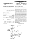
A musical score display apparatus installed in an electronic
musical instrument such as a player piano is designed to
automatically display and change over images of electronic
musical score data on the screen. A user’s voice (or vocal
Correspondence Address:
ization) is input by means of a microphone and an A/D
converter, so that the input voice is subjected to signal
processing to produce voice data. The voice data is then
subjected to voice analysis such as phoneme analysis to
David L. Fehrman
Morrison & Foerster LLP
555 W. 5th Street
35th Floor
determine an arrangement of phonemes that are included in
the input voice and that highly matches one of prescribed
Words listed in advance in a Word dictionary. Recognition
data is created based on the arrangement of the phonemes
and is subjected to command interpretation With reference to
Los Angeles, CA 90013 (US)
(21) Appl. No.:
09/886,758
prescribed commands that are listed in advance in a com
mand database. For example, the command database regis
(22) Filed:
ters a command ‘NEXT’ for designating the neXt page of the
Jun. 20, 2001
musical score to be displayed on the screen and a command
‘BACK’ for designating the previous page of the musical
(30)
Foreign Application Priority Data
score to be displayed on the screen. Herein, one of the
commands that highly matches the recognition data is cho
Jun. 21, 2000
(JP) .................................... .. 2000-186920
Publication Classi?cation
sen and is used to control images of the musical score being
displayed on the screen. In addition, it is possible to detect
a tone volume or a tempo from the input voice. Thus,
musical performance is automatically controlled based on
(51)
Int. Cl.7 ................................................... .. G09B 15/02
(52)
US. Cl. .............................................................. .. 84/478
the electronic musical score data in response to the detected
tone volume or tempo.
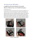
MICROPHONE \/ 220
l
A/D
\/ Z30
CONVERTER
l
_f"’_-__\
221‘?
rz
""""" "t
CONTROLLER
m
21 1
v
v /240
PERFORMANCE
DATA
m\
\
i222
1 ELECTRONIC MUSICAL
CONTROLLER
STORAGE
ELECTRON | G
MUS | CAL
SCORE DATA
H
\A
V
D | SPLAY
PANEL
; 250
*
TONE GENERATOR
\'>
Patent Application Publication
Jan. 31, 2002 Sheet 1 0f 10
US 2002/0011143 A1
0
250
Q
220
Wm‘?
cog:
2002 PLAYER PIANO
FIG. 1
Patent Application Publication
Jan. 31, 2002 Sheet 3 0f 10
US 2002/0011143 A1
FIG. 3
DIGITAL SIGNALS FROM A/D
CONVERTER 230
SIGNAL
PROCESSING
240i CONTROLLER
5241
INSTRUCTION
SIGNALS
vOICE
FOR SIGNAL
DATA
PROCESSING
{242
I
{24221
VOICE
WORD
RECOGNITION
DIRECTIONARY
244
RECOGNITION
DATA
243
‘V
>/
COMMAND
COMMAND
RECOGNITION DATA
INTERPRETATION
T COMMAND DATA
OONNANO
DATABASE
V INEXTJ W51
IBACKJ
DATA
V
K
DISPLAY CONTROL
245
I711
Patent Application Publication
Jan. 31, 2002 Sheet 4 0f 10
US 2002/0011143 A1
Patent Application Publication
Jan. 31, 2002 Sheet 5 0f 10
US 2002/0011143 A1
FIG. 5
S1
N0
FORWARD COMMAND
PAGE BEING
DISPLAYED?
{S3
SUPPLY ELECTRONIC MUSICAL
SCORE DATA OF NEXT PAGE
TO DISPLAY PANEL
@
Patent Application Publication
Jan. 31, 2002 Sheet 6 0f 10
,
5E
J»
1'
A
r
i
J
US 2002/0011143 A1
2
a
l
i
‘
0
1}?1
1.
1~
g
Y
N E
+4
1.
v
.
P
<
‘
_
i
"'
l
.1
I‘
L
0
U
p-q
L_
LL
‘1
1
p
a
_Q\f u
\
,-
F
I
v
‘1
-..
u
T1
\/~\<U
Patent Application Publication
Jan. 31, 2002 Sheet 7 0f 10
US 2002/0011143 A1
FIG. 7
DIGITAL SIGNALS FROM A/D
CONVERTER 230
r
24031 CONTROLLER
I
;241
SIGNAL
PROCESSING
INSTRUCTION
SIGNALS
FOR SIGNAL
PROCESS I NO
VOICE
OATA
242
II
T
2428
f
VOICE
RECOGNITION
WORD
DIREGTIONARY
RECOGNITION
DATA
V
SONG WORD
§246
PAGE
INFORMATION
I
5
245
DISPLAY CONTROL
MUSICAL
Patent Application Publication
Jan. 31, 2002 Sheet 8 0f 10
US 2002/0011143 A1
FIG. 8
INTERVAL DATA 1
RHYTHM DATA 0. 5
2
3
0
2
+1
4
—3 +2 3
I
4
I O. 25 3 O. 5 2
2
I
SONGDATA555I~T7J4555
ELECTRONIC
MUSICAL
SCORE DATA
PAGE DATA
2
FIG. 9
DIGITAL SIGNALS FROM A/D
240b2 CONTROLLER
CONVERTER 230
I
5247
PITCH
DETECTION
NOTE STRING
DATA
'
;248
NOTE
STRING F“ EESIIERSIIIX IEEICAL
COMPARISON
STORAGE 21 I
PAGE
INFORMATION
I
5
DISPLAY CONTROL
245
Patent Application Publication
Jan. 31, 2002 Sheet 9 0f 10
US 2002/0011143 A1
FIG. 10
DIGITAL SIGNALS FROM A/D
24001 CONTROLLER
CONVERTER 230
£241
_
SIGNAL
PROCESSING
INSTRUCTION
SIGNALS
VOICE
DATA
FOR SIGNAL
PROCESSING
‘'
{242
y242a
VOICE
WORD
RECOGNITION
DIRECTIONARY
RECOGNITION
DATA
5
r
249
TEMPO
DETECTION
TEMPO
DATA
‘'
{245
DISPLAY CONTROL
FIG. 11
ONE
TWO
THREE
HI I
I
I
I
I’
TEMPO
DETECTION
120
A“
‘LI
Atz
I22
>
Patent Application Publication
DPIASNLEY
8
Jan. 31, 2002 Sheet 10 0f 10
a!
US 2002/0011143 A1
T.
|
F.
F12IG.
]
CBOUNTRLS
PP
Jan. 31, 2002
US 2002/001 1 143 A1
MUSICAL SCORE DISPLAY FOR MUSICAL
PERFORMANCE APPARATUS
Words listed in advance in a Word dictionary. Recognition
data is created based on the arrangement of the phonemes
and is subjected to command interpretation With reference to
BACKGROUND OF THE INVENTION
prescribed commands that are listed in advance in a com
[0001]
1. Field of the Invention
[0002]
This invention relates to musical score displays that
ters a command ‘NEXT’ for designating a neXt page of the
musical score to be displayed on the screen and a command
mand database. For eXample, the command database regis
display musical scores on screens for musical performance
apparatuses such as player pianos.
‘BACK’ for designating a previous page of the musical score
to be displayed on the screen. Herein, one of the commands
[0003] 2. Description of the Related Art
that highly matches the recognition data is chosen and is
used to control images of the musical score being displayed
[0004] Recently, electronic musical instruments such as
player pianos install functions of displaying musical scores
on screens of displays such as liquid crystal displays.
[0011] The arrangement of the phonemes can be compared
[0005]
FIG. 12 shoWs an eXample of an image of elec
on the screen.
With Words of a song to designate a prescribed position of
the musical score, hence, the corresponding page of the
tronic musical score data that are displayed on a screen of a
musical score is automatically displayed on the screen.
display panel of a player piano. Herein, three staves, notes
[0012] Other than the arrangement of the phonemes, it is
possible to eXtract a string of pitches, by Which retrieval is
performed through the electronic musical score data to ?nd
a string of notes corresponding to the extracted pitches
respectively. Hence, the corresponding page of the musical
and musical symbols in musical notation are displayed in an
upper area of the screen, While graphical images and control
buttons are displayed in a loWer area of the screen.
[0006] A performer (or user) Who plays the player piano
operates the control buttons displayed on the screen to
change over images of the musical score, so that the neXt
page of the musical score is displayed on the screen.
[0007] If the performer uses both of his/her hands to play
the player piano, it is necessary for the performer to tem
porarily stop playing the player piano and change over the
image of the screen. Alternatively, the performer should
rapidly change over the image of the screen even if the
performer does not break the musical performance on the
player piano. In other Words, the conventional player piano
needs manual operations for changing over images of the
score is automatically displayed on the screen.
[0013]
In addition, it is possible to detect a tone volume or
a tempo from the input voice. Thus, musical performance is
automatically controlled based on the electronic musical
score data in response to the detected tone volume or tempo.
BRIEF DESCRIPTION OF THE DRAWINGS
[0014] These and other objects, aspects and embodiments
of the present invention Will be described in more detail With
reference to the folloWing draWing ?gures, of Which:
musical score on the screen, hence, the performer feels
[0015]
dif?culty in continuously playing the player piano because
ance of a player piano that installs a musical score display
apparatus in accordance With a ?rst embodiment of the
the performer cannot concentrate completely on playing the
FIG. 1 is a perspective vieW shoWing an appear
musical performance.
invention;
[0008]
[0016] FIG. 2 shoWs mechanical con?gurations and elec
Other than the aforementioned manual operations
for changing over images of the musical score on the screen,
trical con?gurations provided inside of the player piano
the conventional player piano needs manual operations,
shoWn in FIG. 1;
using the control buttons, for setting or changing tone
volumes and tempos in performance. To set or change them,
function blocks realiZed in a controller shoWn in FIG. 2;
the performer may have a similar problem due to intermit
tent suspension of the musical performance on the player
piano.
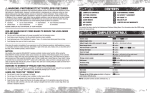
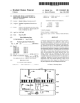
[0017] FIG. 3 is a simpli?ed block diagram shoWing
[0018] FIG. 4 shoWs an eXample of an image of a ?rst
page of electronic musical score data being displayed on the
screen;
SUMMARY OF THE INVENTION
[0009] It is an object of the invention to provide a musical
performance apparatus installing a musical score display
apparatus Whose operations can be easily controlled by
voice commands spoken by a user.
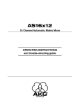
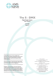
[0019]
FIG. 5 is a ?oWchart shoWing a page forWard
process being eXecuted by a display control block shoWn in
FIG. 3;
[0020] FIG. 6 shoWs an eXample of an image of a pre
scribed page of electronic musical score data incorporating
a practice mark on the screen;
[0010] The present invention provides a musical score
display apparatus that is installed in an electronic musical
instrument such as a player piano and that is designed to
[0021] FIG. 7 is a simpli?ed block diagram shoWing
automatically display and change over images of electronic
second embodiment of the invention;
musical score data on the screen. A user’s vocaliZation (or
user’s voice) is input by means of a microphone and an A/D
converter, so that the input voice is subjected to signal
processing to produce voice data. The voice data is then
subjected to voice analysis such as phoneme analysis to
function blocks realiZed in a controller in accordance With a
[0022]
FIG. 8 shoWs an eXample of a con?guration of
electronic musical score data that are used in the second
embodiment;
[0023] FIG. 9 is a simpli?ed block diagram shoWing
determine an arrangement of phonemes that are included in
function blocks realiZed in a controller in accordance With a
the input voice and that highly match one of the prescribed
modi?ed eXample of the second embodiment;
Jan. 31, 2002
US 2002/001 1 143 A1
[0024] FIG. 10 is a simpli?ed block diagram showing
feedback signal Vy, the servo controller 212 performs a
function blocks realized in a controller in accordance With a
feedback control of the excitation current to be ?oWn across
third embodiment of the invention;
[0025] FIG. 11 is a time chart that is used to explain
operations of the controller of the third embodiment in
Which count voices are input to the player piano; and
[0026]
FIG. 12 shoWs an example of an image of elec
tronic musical score data that are displayed on the screen.
DESCRIPTION OF THE PREFERRED
EMBODIMENTS
[0027] This invention Will be described in further detail by
Way of examples With reference to the accompanying draW
ings.
[0028] [A] First Embodiment
[0029] (1) Con?gurations of First Embodiment
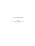
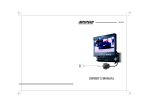
[0030] FIG. 1 shoWs an appearance of a player piano 200,
internal con?gurations of Which are shoWn in FIG. 2.
[0031] First, a mechanical con?guration of the player
piano 200 Will be described With reference to FIG. 2. The
player piano 200 provides an action mechanism 3 for
transmitting an action (i.e., touch or depression) of a key 1
to a hammer 2, a string 4 being struck by the hammer 2, a
solenoid 5 for driving the key 1 to move, a damper 6 for
stopping vibration of the string 4, and a mute mechanism
containing a stopper 8 for regulating movement of the
hammer, Wherein the stopper 8 can move in directions of
arroWs in FIG. 2. Of course, the player piano 200 also
provides the knoWn mechanical members that are generally
installed in the pianos. For example, the player piano 200
also provides a back check 7 for preventing the hammer 2
from unnecessarily moving or deviating. The present speci
the solenoid 5 corresponding to the key 1. Further, the
controller 240 performs a positioning control on the stopper
8 by adequately turning on or off a drive mechanism (not
shoWn).
[0035] As described above, based on the performance data
supplied from the storage unit 211, the controller 240
performs positioning controls respectively on the solenoids
5 corresponding to the keys 1 by means of the servo
controller 212. Thus, it is possible to perform ‘mechanical’
musical tone generation controls for actually striking the
strings 4.
[0036] The player piano 200 provides the prescribed num
ber of keys 1, Which are respectively coupled With key
sensors 221. The key sensors 221 are provided to detect
operations of the keys 1 respectively.
[0037]
The key sensors 221 are arranged beneath loWer
surfaces of the keys 1, so that they output signals represent
ing variations of states of the keys 1 (namely, depression and
release of the keys 1) to the controller 240.
[0038] Based on output signals of the key sensors 221, the
controller 240 supplies control signals to the electronic
musical tone generator 222 to control generation of elec
tronic musical tones. When electronically generating the
musical tones in response to operations of the keys 1, the
controller 240 stops the hammers 2 striking the strings 4 by
performing the aforementioned positioning controls on the
stoppers 8. In other Words, the controller 240 performs
musical tone suppression controls to suppress the musical
tones being generated by striking the strings 4. As described
above, the player piano 200 provides ‘electronic’ musical
tone generation controls in addition to the ‘mechanical’
musical tone generation controls that are made by actually
?cation excludes description of the aforementioned
striking the strings 4. Herein, the electronic musical tone
mechanical members that are not closely related to essential
matters of the present embodiment.
generation controls are made such that electronic musical
tones are controlled in response to the performance data by
supplying control signals to the electronic musical tone
generator 222, Which is con?gured by a sound source and a
[0032] Next, an electric con?guration of the player piano
200 Will be described With reference to FIG. 2, Wherein the
player piano 200 is basically con?gured using the general
electronic components such as the CPU, ROM and RAM.
Namely, a controller 240 performs overall controls on the
player piano 200. A servo controller 212 controls a servo
mechanism based on control signals output from the con
troller 240. An electronic musical tone generator 222 gen
erates electronic musical tones based on control signals
output from a key sensor 221, Which Will be described later.
Adisplay panel 250 is con?gured by a liquid crystal display
to display images of electronic musical score data on a
screen. In addition, a storage unit 211 stores electronic
musical score data and performance data therein.
[0033] Based on the performance data supplied from the
storage unit 211, the controller 240 supplies controls signals
to the servo controller 212 in order to control positions of the
speaker (or speakers).
[0039] The player piano 200 of the present embodiment
also provides a microphone 220 and an analog-to-digital
converter (A/D converter) 230.
[0040] The microphone 220 has a directivity in a pre
scribed direction. Therefore, the microphone 220 is mounted
on a certain location of the player piano 200 at Which it can
ef?ciently pick up the voice of the user (see FIG. 1). The
microphone 220 picks us the user’s voice and converts it to
analog signals. The A/D converter 230 converts the analog
signals to digital signals, Which are forWarded to the con
troller 240.
[0041] Namely, the controller 240 receives user’s voice
commands (or user’s vocaliZed commands), Which are
keys 1 at prescribed times respectively.
picked up and supplied thereto by the microphone 220 and
[0034] Speci?cally, based on the control signal supplied
mands, the controller 240 performs image changeover con
the A/D converter 230. RecogniZing the user’s voice com
from the controller 240, the servo controller 212 produces an
trols for changing over images of the musical score on the
excitation current, corresponding to the prescribed position
screen of the display panel 250. That is, the controller 240
has the image changeover controls in addition to the fore
going performance controls such as the mechanical and
electronic musical tone generation controls.
of the key 1, to How across the solenoid 5 corresponding to
the key 1. In addition, the servo controller 212 inputs a
feedback signal Vy from the solenoid 5. Using such a
Jan. 31, 2002
US 2002/001 1 143 A1
[0042] Next, display image controls of the controller 240,
Which are characterizing features of the present invention,
input command) and other examples of commands that have
relatively high degrees of match. The chosen commands are
Will be described With reference to FIG. 3.
converted to command data to suit the prescribed data
[0043] FIG. 3 shoWs simpli?ed function blocks provided
control block 245. The command data are supplied to the
inside of the controller 240. Namely, the controller 240
provides a signal processing block 241, a voice recognition
format that can be uniquely interpreted for the display
display control block 245.
block 242, a command interpretation block 243, a command
database 244 and a display control block 245.
[0047] The command database 244 manages the Words
regarding the commands for changing over images of the
[0044] The signal processing block 241 performs signal
dence With the command data respectively. Concretely
processing on digital signals output from the A/D converter
230, so that voice data are created and are forWarded to the
voice recognition block 242. It is possible to change the
content of the signal processing in response to instruction
signals being supplied from the voice recognition block 242.
[0045]
The voice recognition block 242 divides the voice
electronic musical score data on the screen in correspon
speaking, FIG. 3 shoWs an example of the content of the
command database 244 in Which the Word “TUGI” for
designating the next page of the electronic musical score
data to be displayed on the screen is related to the command
‘NEXT’ for instructing the display panel 250 to display the
next page of the electronic musical score data on the screen.
data, output from the signal processing block 241, into plural
In addition, the Word “MAE” for designating the previous
data by units of frames (hereinafter, simply referred to as
“frame data”). Sound models are created based on phoneme
models, Which are registered in advance. Phoneme analysis
page of the electronic musical score data to be displayed on
the screen is related to the command ‘BACK’ for instructing
is performed by comparison betWeen the frame data and
electronic musical score data on the screen.
sound models, Waveforms of Which are compared With each
[0048]
other. Thus, the phoneme analysis determines phonemes
having high likelihood in Which the frame data highly match
With the sound models in their Waveforms. That is, the voice
recognition block 242 effects phoneme analysis processes to
provisionally determine arrangements of the phonemes,
Which are respectively compared With Words that are regis
tered in a Word dictionary 242a in advance. Thus, the voice
recognition block 242 chooses the Words that highly match
With the arrangements of the phonemes. Using those Words,
the voice recognition block 242 performs syntax analysis
using language models. Through the syntax analysis, the
voice recognition block 242 determines a sentence (or
statement) that can be read in the Japanese language, for
example. Then, the voice recognition block 242 produces
recognition data representing the determined sentence,
the display panel 250 to display the previous page of the
Based on the command data output from the com
mand interpretation block 243, the display control block 245
performs various types of display controls such as
changeovers of images of the electronic musical score data
to be displayed on the screen of the display panel 250.
[0049] (2) Operations of First Embodiment
[0050] Next, operations of the player piano 200 Will be
described With respect to a user’s musical performance in
accordance With the ?rst embodiment of the invention.
[0051] First, the user of the player piano 200 operates an
operator console (not shoWn) to select a musical tune to be
performed. Then, the display control block 245 reads from
the storage unit 211, electronic musical score display data
corresponding to the selected musical tune. The display
Which are forWarded to the command interpretation block
control block 245 produces electronic musical score data for
243. Incidentally, the Word dictionary 242a registers in
advance the prescribed Words regarding the commands for
displaying a ?rst page of the musical score on the screen.
use in controls of automatic performance of the player piano
200. For example, it registers the Words such as “start” and
“stop” that instruct start and stop of the automatic perfor
mance respectively. In addition, the Word dictionary 242a
also registers other Words regarding the commands for use
in changeovers of images of electronic musical score data on
the screen. For example, it registers the Japanese Words such
as ‘7%(or TUGI)” and '?l(or MAE)” (i.e., “next” and
“back” in English) that instruct the display panel 250 to
change over images of the electronic musical score data on
the screen. Herein, “TUGI” instructs the display panel 250
to display the next page folloWing the page presently dis
played on the screen, While “MAE” instructs the display
panel 250 to display the previous page on the screen.
[0046] The command interpretation block 243 compares
the recognition data output from the voice recognition block
242 With command data representing the prescribed com
mands that are registered in the command database 244 in
The electronic musical score data are supplied to the display
panel 250. Thus, the display panel 250 displays the ?rst page
of the musical score on the screen.
[0052] FIG. 4 shoWs an example of the ?rst page of the
musical score being displayed on the screen of the display
panel 250.
[0053] The display panel 250 displays basically three
types of information, namely performance information ‘a’,
tempo information ‘b’ and title information ‘c’, on the
screen. The information ‘a’ corresponds to the ?rst page of
the musical score shoWing three staves on Which musical
symbols and musical notes designating pitches and duration
are adequately arranged in the prescribed musical notation.
Hence, the user is able to play the player piano 200 With
reference to the musical score displayed on the screen.
[0054]
The tempo information ‘b’ designates a tempo that
the user uses as the standard of velocity in musical perfor
mance on the musical score. In the case of FIG. 4, the tempo
advance. Through comparison, the command interpretation
information b designates a certain performance tempo by
block 243 interprets the recognition data to choose the
commands that highly match With the recognition data.
Herein, the command interpretation block 243 chooses a
command having a highest degree of match (namely, a voice
Which sixty quarter notes are to be played Within one minute.
Incidentally, the user is able to arbitrarily set or change the
performance tempo by operating the operator console. Once
the user sets the performance tempo on the screen, the
Jan. 31, 2002
US 2002/001 l 143 Al
display control block 245 controls the display panel 250 to
sequentially ?ash the notes that the user should play in
response to the performance tempo, Which is displayed as
the tempo information b in an upper left portion of the
screen.
[0055]
The title information ‘c’ shoWs the title of the
musical tune, the name of a composer, etc. The title infor
mation c also contains information representing the present
position of the musical score of the musical tune being
presently played in accordance With progression of musical
performance. For example, the information shoWs a serial
number of the measure that is counted from a ?rst measure
of the musical score of the musical tune.
[0056] Suppose that the user produces the Word “TUGI”
on the microphone 220 of the player piano 200 under the
condition Where the display panel 250 is presently display
ing the ?rst page of the musical score on the screen. In that
is made as to Whether the last page of the musical score is
presently displayed on the screen or not. If “YES” in step S2,
the display control block 245 immediately ends the page
forWard process. If the display control block 245 determines
in step S2 that the display panel 250 does not display the last
page of the musical score on the screen, in other Words, if
“NO” in step S2, the How proceeds to step S3 in Which the
display control block 245 reads from the RAM (not shoWn),
the neXt page of electronic musical score data, Which are
supplied to the display panel 250. Thus, the display panel
250 displays the neXt page of the musical score on the
screen.
[0058] The aforementioned description is made With
respect to the case Where the Word “TUGI” for designating
the neXt page of the musical score is input to the player piano
200. Similar operations and processes are made With respect
to another case Where the Word “MAE” for designating the
previous page of the musical score is input to the player
case, the Word “TUGI” is picked up by the microphone 220
and is converted to digital signals by the A/D converter 230.
Upon receipt of the digital signals, the controller 240 starts
voice recognition processes and the like. Concretely speak
ing, the user’s voice is input to the player piano 200 by
prescribed keyWord toWard the microphone 220, the display
means of the microphone 220 and A/) converter 230, so that
panel 250 correspondingly changes over images of the
piano 200.
[0059] According to the player piano 200 of the present
embodiment described above, When the user speaks the
the signal processing block 241 produces the corresponding
musical score being displayed on the screen. Therefore, even
voice data, Which are forWarded to the voice recognition
block 242. In the voice recognition block 242, the voice data
When the user plays the player piano 200 With both of his/her
are subjected to phoneme analysis to provisionally deter
mine an arrangement of phonemes included in the user’s
screen of the display panel 250 Without intermittently break
ing musical performance on the player piano 200. Thus, the
voice. The arrangement of the phonemes is compared With
the Words that are registered in the Word dictionary 242a.
user is able to concentrate his/her mind on the musical
hands, the user is able to change over the images on the
performance of the player piano 200.
Thus, the voice recognition block 242 chooses a Word that
highly matches With the arrangement of the phonemes
Within the Words registered in the Word dictionary 242a. The
[0060] The present embodiment originally describes that
the display panel 250 merely displays images of the elec
Word dictionary 242a coupled With the voice recognition
tronic musical score data on the screen. In this case, the
block 242 registers the Word “TUGI” that indicates a page
display panel 250 is not necessarily designed to display
migration in the forWard direction (namely, page forWard)
control buttons for the user’s manual operations together
With respect to the electronic musical score data. Therefore,
With the musical score on the screen. For this reason, even
the voice recognition block 242 determines the Word
“TUGI” based on the phoneme analysis result, so that
being conventionally used, it is possible to broaden the
corresponding recognition data are forWarded to the com
overall area for displaying the musical score on the screen
if the display panel 250 employs the same siZe of screen
mand interpretation block 243. Upon receipt of the recog
compared With conventional displays.
nition data from the voice recognition block 242, the com
mand interpretation block 243 refers to the command
[0061] (3) Modi?ed EXamples
[0062] (a) First Modi?ed EXample
database 244 to make a determination as to Which command
the recognition data actually means. As described before, the
command database 244 stores the Word “TUGI” represent
ing the page forWard of the electronic musical score data in
correspondence With the command NEXT for instructing the
page forWard of the electronic musical score data on the
screen. Therefore, the command interpretation block 243
reads from the command database 244, the command NEXT
that corresponds to the recognition data output from the
voice recognition block 242. Then, the command NEXT is
sent to the display control block 245.
[0063] The ?rst embodiment originally describes that
images of electronic musical score data being displayed on
the screen of the display panel 250 are changed over in
response to human voices (or user’s voice commands).
Instead of changing over the images of the electronic
musical score data, it is possible to change over siZes and
shapes of staves and musical symbols of the musical score
on the screen in response to the human voices. Concretely
speaking, it is possible to provide a magni?cation function
by Which images of electronic musical score data can be
[0057] Receiving the command NEXT from the command
interpretation block 243, the display control block 245 starts
magni?ed by prescribed factors (Which range betWeen ‘1’
to eXecute a page forWard process shoWn in FIG. 5. Herein,
provide a division function (or screen split function) by
the How ?rstly proceeds to step SI in Which a decision is
Which images of electronic musical score data can be
made as to Whether a page forWard command ‘NEXT’ for
the electronic musical score data is input or not. If the
and ‘10’, for example) on the screen, and it is possible to
divided into multiple sections being arranged in a vertical
mand NEXT being output from the command interpretation
direction on the screen. For eXample, an image of the
electronic musical score data is divided into tWo sections,
Which are respectively displayed in an upper area and a
block 243, the How proceeds to step S2 in Which a decision
loWer area on the screen. In order to facilitate the aforemen
display control block 245 detects the page forWard com
Jan. 31, 2002
US 2002/001 l 143 Al
tioned functions, the Word dictionary 242a of the voice
recognition block 242 and the command database 244
register a Word “Zoom” for designating magni?cation of
data is forWarded to the display control block 245. Based on
the command data output from the command interpretation
block 243, the display control block 245 supplies the elec
images of the electronic musical score data and a Japanese
tronic musical score data of page 2 incorporating the prac
Word 7“/i1“/or “BUNKATSU” (i.e., “divide” in English)
for designating division of images of the electronic musical
tice mark ‘A’ to the display panel 250. Thus, the display
panel 250 automatically changes over images of the musical
score data. In addition, the command database 244 also
registers a command ‘EXPAND’ in relation With the Word
“Zoom” and a command ‘DIVIDE’ in relation With the Word
“BUNKATSU”. Thus, the user is able to freely change over
the siZes and shapes of the electronic musical score data on
the screen of the display panel 250 by his/her voice com
mands.
score on the screen from page 10 to page 2.
[0064] (b) Second Modi?ed Example
[0065] The ?rst embodiment originally describes that the
electronic musical score data are con?gured by the perfor
mance information ‘a’, tempo information ‘b’ and title
information ‘c’ (see FIG. 4). It is possible to additionally
introduce a practice mark ‘d’, Which is displayed at an
arbitrary position Within the area of the performance infor
mation ‘a’ on the screen.
[0066] Concretely speaking, the controller 240 incorpo
rates a practice mark Write tool, Which operates responsive
to user’s manual operation of the operator console. That is,
by manually operating the operator console, the user is able
to display a practice mark ‘d’ at an arbitrary position Within
the area of the performance information ‘a’ on the screen.
FIG. 6 shoWs that a letter ‘A’ is displayed as the practice
mark ‘d’ above a lowest staff Within three staves of the
performance information ‘a’ on the screen. Incidentally, the
practice mark ‘d’ is not necessarily limited to one prescribed
symbol such as the letter ‘A’. Therefore, it is possible to
provide plural symbols such as letters ‘A’ and ‘B’ as the
practice mark ‘d’. In addition, it is possible to arbitrarily add
or delete the practice mark d on the screen.
[0067] To realiZe incorporation of the practice mark d, the
Word dictionary 242a of the voice recognition block 242 and
[0070] If the controller 240 is con?gured as described
above, the user is able to display images of the electronic
musical score data together With the practice mark on the
screen by simple operations.
[0071] (c) Third Modi?ed EXample
[0072] The second modi?ed eXample describes that the
user manually operates the operator console to add a practice
mark to the musical score on the screen. Of course, this
technique is applicable to a system in Which the user
designates a position of a practice mark to be displayed on
the screen by his/her voice. Concretely speaking, the Word
dictionary 242a and the command database 244 register the
Japanese Words “KAKIKOMI MODE” (i.e., “Write mode”
in English) for designating a changeover operation from an
automatic performance mode to a practice mark Write mode.
In addition, the command database 244 also registers a
command ‘MODE WRITE’ in relation With the Words
“KAKIKOMI MODE”.
[0073]
In order to designate a position of a practice mark
to be displayed on the screen, the user speaks the Words
“KAKIKOMI MODE” toWard the microphone 220 of the
player piano 200. Thus, the player piano 200 is set in a
practice mark Write mode. To further designate the concrete
position of the practice mark on the screen, the user speaks
Words “SHOSETSU BANGO 11” (i. e., “measure or bar
number 11” in English) and “MARK A” toWard the micro
phone 220. Herein, “11” that is spoken to folloW
“SHOSETU BANGO” is a serial number of the measure or
bar that is counted from the ?rst measure or bar Within the
the command database 244 register a Word “MARK A” for
musical score, While “A” that is spoken to folloW “MARK”
is an alphabetic letter that is selected from among plural
designating the practice mark ‘A’ to be incorporated into the
practice marks A, B, . . . , for eXample. All of the afore
electronic musical score data being displayed on the screen.
mentioned Words and commands are registered in the Word
dictionary 242a and the command database 244 in advance.
When the user speaks the Words of “SHOSETSU BANGO
11” and “MARK A” toWard the microphone 220 of the
In addition, the command database 244 also registers a
command ‘JUMP A’ in relation With the Word “MARK A”.
[0068] If the controller 240 is con?gured to incorporate
the practice mark Write tool described above, the user can
instruct the display panel 250 to display images of electronic
musical score data together With the practice mark ‘A’ on the
screen at any time. Concrete operations Will be described
beloW.
[0069] Suppose that the display panel 250 initially dis
plays an image of electronic musical score data of page 10,
Which differs from an image of electronic musical score data
of page 2 incorporating a practice mark ‘A’, on the screen.
In this case, When the user Wishes to practice the prescribed
part of the musical score With reference to the image of the
electronic musical score data incorporating the practice
mark ‘A’, the user speaks Words “MARK A” toWard the
microphone 220 of the player piano 200. Inputting such
Words by means of the microphone 220, the command
interpretation block 243 reads the command ‘JUMP A’
corresponding to the registered Word “MARK A” from the
command database 244, so that the corresponding command
player piano 200, the controller 240 automatically inputs the
prescribed command that instructs the display panel 250 to
display a practice mark A at a position of measure number
11 on the screen. Thus, the display panel 250 additionally
displays the practice mark A at the position of the measure
number 11 of the musical score Within the area of the
performance information ‘a’ on the screen.
[0074] As described above, if the apparatus alloWs the
user to designate the position of the practice mark on the
screen by his/her voice, it is possible to additionally display
the practice mark at the desired position Within the musical
score on the screen even if the user cannot presently use both
of his/her hands because of progression of musical perfor
mance on the player piano 200, for eXample.
[0075] As described above, designation of the position of
the practice mark on the screen can be made by the user’s
voice because the electronic musical score data do not
originally designate the position of the practice mark in
Jan. 31, 2002
US 2002/001 1 143 A1
advance. Instead, designation of the position of the practice
mark can be made using a prescribed format of the electronic
musical score data by Which the practice mark is added to
the performance information ‘a’ so that it is automatically
displayed at the prescribed position on the screen. In that
case, the user is also able to change over images of the
musical score on the screen by his/her voice.
[0076]
[0081] (6) Sixth Modi?ed Example
[0082] The ?rst embodiment and its modi?ed examples
describe that pages of electronic musical score data are
changed over on the screen in response to the user’s voice.
In the case Where the pre-recorded musical performance is
reproduced on the player piano 200 in the automatic per
formance mode and the like, it is possible to change over
Suppose that a practice mark A is added to the
positions of reproduction of the musical performance in
electronic musical score data at measure number 33 Which
response to changeovers of pages of the musical score being
displayed on the screen. This function can be actualiZed by
appears on page 3 of the musical score, for example. In this
case, When the user speaks the Words “MARKA” toWard the
microphone 220 of the player piano 200, the display panel
providing a reproduction position control block subsequent
to the command interpretation block 243. The reproduction
250 automatically displays on the screen, the musical score
position control block makes a determination as to Which
of page 3 in Which the practice mark A has been already
displayed at the prescribed position. In order to facilitate an
image changeover With respect to the musical score of the
prescribed page incorporating the practice mark A on the
part of the performance data is to be reproduced on the basis
of the command data output from the command interpreta
tion block 243. In response to the determination result, the
screen, it is necessary to provide the user With information
the electronic musical tone generator 222, so that the repro
duction position is to be changed over in the musical score.
Based on the control data, the electronic musical tone
regarding the position of the practice mark A Within the
musical score. In order to do so, it is possible to display the
measure number and page of the musical score, to Which the
practice mark A is added, in the area of the title information
‘c’ on the screen.
[0077] (d) Fourth Modi?ed Example
[0078] The third modi?ed example described the con?gu
ration of the apparatus in Which the display panel 250
automatically displays an image of the electronic musical
score data of the prescribed page, Which is speci?ed by the
practice mark and measure number. Instead, it is possible to
directly input a voice command for designating the speci?c
page of the electronic musical score data incorporating the
reproduction position control block outputs control data to
generator 222 generates musical tones, by Which the musical
performance is reproduced in accordance With the electronic
musical score data Whose pages are successively changed
over on the screen. In the reproduction of the performance
data described above, the electronic musical tone generator
222 is controlled by the control data. In the automatic
performance that is realiZed With sequential changeovers of
pages of the electronic musical score data on the screen, the
servo controller 212 is to be controlled based on the control
data. Because the automatic performance can be easily
realiZed by partially modifying the reproduction of the
practice mark.
[0079] (e) Fifth Modi?ed Example
performance data, details of the automatic performance on
the player piano 200 are omitted in the present speci?cation.
[0080] The second and third modi?ed examples describe
that images of electronic musical score data of multiple
[0083] [B] Second Embodiment
[0084] (1) Con?guration of Embodiment
pages are changed over on the screen With reference to the
practice mark. Instead, it is possible to change over images
of electronic musical score data of multiple pages on the
screen With reference to the measure number (i.e., the serial
number of the measure that is counted from the ?rst measure
of the musical score of the musical tune), Which is desig
nated by the user. As described before, the display panel 250
displays in the area of the title information c on the screen,
information indicating the number of the measure that is
counted from the ?rst measure of the musical score of the
[0085] The ?rst embodiment is designed such that the
controller 240 performs display controls on the electronic
musical score data in response to the user’s voice com
mands. The second embodiment is designed such that a
controller 240a performs display controls on the electronic
musical score data in response to Words of a song Which are
actually sung by the user. The second embodiment employs
the same hardWare con?guration of the player piano 200
shoWn in FIG. 2, hence, the description thereof Will be
musical tune and is being presently played by the user. This
information is very useful for the user, particularly in the
practice of the musical performance on the player piano 200.
omitted.
That is, the user memoriZes the number of the measure (e.g.,
compared With the ?rst embodiment shoWn in FIG. 3, the
controller 240a additionally provides a song Word position
detection block 246, Which is substituted for the aforemen
tioned command interpretation block 243 and the command
measure number ‘11’) of the musical score at Which the user
frequently makes errors, in spite of repeatedly practicing
many times. Therefore, the user can easily instruct the
display panel 250 to display the prescribed page of the
electronic musical score data incorporating the practice
mark by designating the memoriZed measure number. Inci
dentally, the aforementioned ?fth modi?ed example that
[0086] FIG. 7 shoWs function blocks for use in the con
troller 240a in accordance With the second embodiment. As
database 244.
[0087]
The song Word position detection block 246 oper
ates responsive to Words of a song of a musical tune that are
alloWs the user to change over the pages of the electronic
musical score data by designating the measure numbers can
sequentially sung by the user on the microphone 220. Based
be easily actualiZed using the same con?guration of the
controller 240 employed in the ?rst modi?ed example,
hence, the description of the controller 240 for use in the
?fth modi?ed example is omitted in the present speci?ca
the storage unit 211, the song Word position detection block
246 detects a position of the song containing plenty of Words
(or phonemes) one of Which presently matches With the
tion.
from the user’s mouth and is picked up by the microphone
on the electronic musical score data being transferred from
Word (or phoneme) of the song that is presently produced
Jan. 31, 2002
US 2002/001 1 143 A1
220. Then, the song Word position detection block 246
[0096]
outputs a detection result to the display control block 245. In
the above, the song Word detection block 246 performs
220 While pronouncing Words of the song by each of
syllables, the controller 240a starts voice recognition pro
retrieval on the electronic musical score data to ?nd out the
cesses.
position of the song presently matched With the Word of the
song actually produced from the user’s mouth. Herein, the
[0097]
electronic musical score data are described in a table form,
an example of Which Will be described With reference to
FIG. 8.
[0088]
FIG. 8 shoWs a main portion of the con?guration
of the electronic musical score data. Herein, the electronic
musical score data are con?gured by multiple sets of data,
namely interval data, rhythm data, song data and page data.
When the user 220 sings a song on the microphone
Suppose that the user presently pronounces a Word
of the song of “TONAKAI” (i.e., “reindeer” in English),
Which is made up of four Japanese syllables, on the micro
phone 220.
[0098] The aforementioned user’s voice is input to the
player piano 200 by means of the microphone 220 and A/D
converter 230, so that the corresponding voice data are
supplied to the voice recognition block 242 by means of the
signal processing block 241. The voice recognition block
Other than these data, the electronic musical score data also
contain data representing the title of the musical tune, name
of the composer, name of the metrician, etc., Which are not
242 performs phoneme analysis (or syllable analysis) on the
closely related to the present invention, hence, the descrip
tion thereof Will be omitted.
that are registered in the Word dictionary 242a in advance.
Then, the voice recognition block 242 chooses a Word
[0089]
having the highest degree of match. In the second embodi
ment, the Word dictionary 242a of the voice recognition
The interval data expresses seven musical intervals
for solfa syllables ‘do’ (C) to ‘si’ (B) by numbers, Wherein
‘0’ is allocated to ‘do’, and semitone is expressed using the
number ‘1’. In the musical scale, ‘do’ sharp (#) that is a
semitone higher than ‘do’ is expressed by the number ‘1’,
and ‘re’ that is a semitone higher than ‘do’ sharp is expressed
by ‘2’, for example. In addition, a symbol ‘+’ is used to
express one octave higher than the reference note in the
certain musical scale, and a symbol ‘—’ is used to express one
octave loWer than the reference note in the certain musical
scale. Those symbols are Written in the left positions of the
numbers shoWing the intervals (or notes). For example, ‘+1’
input voice data to provisionally determine an arrangement
of phonemes (or syllables), Which is compared With Words
block 242 registers a variety of Words, Which are used for
various songs, in addition to the prescribed Words that are
related to the prescribed controls of the player piano 200.
Therefore, the voice recognition block 242 produces recog
nition data representing the Word “TONAKAI” that is deter
mined based on the phoneme analysis result. The recogni
tion data are supplied to the song position detection block
246.
[0099] Receiving the recognition data from the voice
recognition block 242, the song position detection block 246
indicates a note of ‘do’ sharp that is one semitone and one
refers to electronic musical score data that are transferred
octave higher than the reference note ‘do’.
thereto from the storage unit 211. Herein, the song position
[0090] The rhythm data are expressing using units of
quarter-note lengths, Wherein one quarter-note length is
detection block 246 performs retrieval as to Which part of the
song listed in the electronic musical score data matches the
expressed by the number ‘1’. For example, ‘0.5’ expresses a
half of the quarter note, namely an eighth note, and ‘4’
expresses a Whole note corresponding to a sum of four
quarter notes.
Word “TONAKAI” that is pronounced by the user and is
represented by the recognition data. As described before, the
electronic musical score data contain page data representing
pages to Which the interval data, rhythm data and song data
belong. Based on the page data, the song Word position
prescribed order, Wherein the Words are described at the
detection block 246 can determine Which page of the musi
cal score the corresponding Word of the song is Written.
Based on the determination result, the song Word position
prescribed positions in connection With the pitch data and
rhythm data respectively. FIG. 8 shoWs Japanese syllables
the musical score the Word “TONAKAI” is Written. The
[0091]
The song data are created in the text form that
describes an arrangement of Words (or syllables) in the
detection block 246 performs recognition of Which page of
such as 777(ie, “la la la . . . ” in English).
recognition result is supplied to the display control block
[0092] The page data shoWs a number of the page of the
electronic musical score data to Which the pitch data, rhythm
245 as page information. If the song Word detection block
246 recogniZes that the Word “TONAKAI” is Written on
page 2 of the musical score, it outputs page information for
data and song data presently belong.
controlling the display control block 245 to display elec
[0093] Incidentally, the electronic musical score data are
not necessarily described in the aforementioned format
shoWn in FIG. 8. Hence, it is possible to use pitch data
instead of the interval data.
tronic musical score data of page 2 on the screen.
[0100]
In the aforementioned condition, the display con
trol block 245 reads the electronic musical score data of page
2 from the RAM on the basis of the page information output
from the song Word position detection block 246. The read
[0094] (2) Operations of Second Embodiment
[0095] Next, a description Will be given With respect to
operations of the second embodiment. Herein, the descrip
tion is made in consideration of the situation Where the user
electronic musical score data are supplied to the display
panel 250. As a result, the display panel 250 displays on the
screen, page 2 of the musical score in Which the Word
“TONAKAI” is Written.
sings a song on the microphone 220 of the player piano 200
[0101] As described above, the player piano 200 of the
While the display panel 250 sequentially changes over
images of electronic musical score data on the screen in the
second embodiment alloWs the user to designate the desired
position of the musical score being displayed on the screen
automatic performance mode.
by pronunciation (or uttering) of Words of the song. Of
Jan. 31, 2002
US 2002/001 1 143 A1
musical score on the screen in response to user’s pronun
block 247 produces pitch string data, Which are forWarded to
the note string comparison block 248.
ciation of Words of the song. In addition, it is possible to
modify the second embodiment similarly to the sixth modi
?ed example of the ?rst embodiment. That is, When the
[0107] Based on the electronic musical score data (spe
ci?cally, the interval data) that are transferred from the
course, it is possible to simply change over pages of the
player piano reproduces a musical performance by the
automatic performance function thereof, it is possible to
automatically change over the reproduction positions of the
musical performance in response to changeovers of pages of
the musical score on the screen. Concretely speaking, a
reproduction position control block is provided subsequent
to the song Word position detection block 246. Herein, the
reproduction position control block makes a determination
as to Which part of the musical score is to be reproduced
based on the page information output from the song Word
position detection block 246. Then, the reproduction posi
tion control block produces control data in response to the
determination result. The control data are supplied to the
electronic musical tone generator 222 to enable changeovers
of the reproduction positions in the musical score. Based on
the control data, the electronic musical tone generator 222
generates musical tones, by Which electronic musical score
data of the prescribed page are automatically reproduced.
That is, the electronic musical tone generator 222 is con
trolled to reproduce the prescribed page of the electronic
musical score data by the speaker(s) and the like. Instead, it
is possible to control the servo controller 212 to realiZe
automatic performance (or auto play of the player piano) on
the prescribed page of the electronic musical score data.
storage unit 211, the pitch string comparison block 248
performs retrieval of the part of the electronic musical score
data Which matches the pitch string data output from the
pitch detection block 247, and it also performs retrieval of
the page of the musical score on Which the pitch string is
Written. Retrieval results are supplied to the display control
block 245 as page information.
[0108] According to the aforementioned con?guration of
the controller 240b, as the user’s devoiced sounds in hum
ming are input to the player piano by means of the micro
phone 220 and A/D converter 230, a string of pitches are
sequentially extracted from the user’s devoiced sounds.
Upon detection of the pitch string of the electronic musical
score data that matches the extracted pitch string, the con
troller 240b automatically changes over the pages of the
musical score on the screen. Incidentally, concrete opera
tions for detecting the pitches from the user’s devoiced
sounds in humming can be understood by the description of
the second embodiment, and the description thereof Will
therefore be omitted. In addition, it is possible to further
modify the controller 240b such that reproduction positions
are automatically changed over in response to changeovers
of pages of the musical score on the screen, Which have been
already described in the description of the second embodi
Details of the automatic performance of the player piano are
omitted because it can be easily realiZed similarly to the
ment.
electronic reproduction of the electronic musical score data.
[0109] [C] Third Embodiment
[0102] (3) Modi?ed Examples
[0110] (1) Con?guration of Third Embodiment
[0103] The second embodiment describes a player piano
that is con?gured to control images of electronic musical
[0111] The player piano of the second embodiment and its
modi?ed example is designed to control changeovers of
score data being displayed on the screen in response to
user’s pronunciation of Words of a song. Herein, the user is
not alWays required to sing a song such that each of the
images of electronic musical score data on the screen and
Words (or syllables) is clearly pronounced on the micro
phone 220. That is, the player piano can be designed to
respond to someWhat ‘unclear’ and ‘informal’ manners of
singing such as humming. That is, the player piano can be
reproduction of musical performance in response to the
user’s voices corresponding to Words of a song or the user’s
devoiced sounds in humming. In contrast, the player piano
of the third embodiment is designed to set a tempo for the
musical performance based on the electronic musical score
modi?ed to control images of electronic musical score data
being displayed on the screen upon detection of pitches of
devoiced sounds that are produced by the user in humming.
data by user’s voices for counting numbers and the like. For
example, When the user speaks “one”, “tWo”, “three” and
“hi V’, the player piano automatically sets a certain tempo for
the musical performance. In the present embodiment, the
[0104] FIG. 9 shoWs function blocks for use in a control
ler 240b in accordance With a modi?ed example of the
second embodiment. That is, the controller 240b contains a
“hi !” Will be referred to as count voices.
pitch detection block 247, a note string comparison block
troller 240c in accordance With the third embodiment. As
248 and a display control block 245.
[0105] The pitch detection block 247 inputs devoiced
sounds, Which are produced by the user humming a song or
a melody, by means of the microphone 220 and A/D
converter 230. Herein, the pitch detection block 247 extracts
pitches from the devoiced sounds of the user in humming, so
that it forms a string of the extracted pitches (hereinafter,
simply referred to as an extracted pitch string).
[0106] The pitch detection block 247 further converts the
extracted pitch string to the prescribed data form that the
note string comparison block 248 can uniquely interpret, for
example, the data form that is equivalent to the form of the
electronic musical score data. Thus, the pitch detection
aforementioned voices such as “one”, “tWo”, “three” and
[0112]
FIG. 10 shoWs function blocks for use in a con
compared With the foregoing controller 240 shoWn in FIG.
3, the controller 240c is characteriZed by providing a tempo
detection block 249 betWeen the voice recognition block 242
and display control block 245.
[0113]
When the user pronounces the count voices on the
microphone 220, the corresponding voice data are sent to the
voice recognition block 242, Which in turn produces recog
nition data representing the count voices. The recognition
data are forWarded to the tempo detection block 249. The
tempo detection block 249 calculates a tempo based on the
reception timing of the recognition data. The calculated
tempo is supplied to the display control block 245 as tempo
data.
Jan. 31, 2002
US 2002/001 1 143 A1
[0114] The voice recognition block 242 also inputs other
voices (such as the Word “start” for designating a start of
musical performance) other than the count voices by means
of the microphone 220 and A/D converter 230. The voice
recognition block 242 installs a voice type discrimination
function for making a determination as to Whether the input
voices correspond to the count voices (i.e., “one, tWo, three,
hi V’) or the other voices. If the voice recognition block 242
determines that the input voices correspond to the count
voices, it outputs the corresponding recognition data to the
tempo detection block 249. If the voice recognition block
242 determines that the input voices correspond to the other
voices, it outputs the corresponding recognition data to the
command interpretation block 243 (not shoWn in FIG. 10).
[0115] (2) Operations of Third Embodiment
[0116] Next, operations of the player piano of the third
embodiment in Which count voices are input Will be
described With reference to FIG. 11.
[0117] In order to set a desired tempo for musical perfor
mance on the player piano, the user sequentially pronounces
the count voices such as “one”, “tWo”, “three” and “hi !”
toWard the microphone 220. The count voices are input to
the player piano by means of the microphone 220 and A/D
converter 230. In the controller 240c, the signal processing
[0120]
Al(ave) :
Ar] + A12
2
T(temp) : W
[0121] The tempo detection block 249 performs calcula
tions based on times, Which are needed for inputting the
prescribed keyWords such as “one”, “tWo” and “three” for
use in setup of the tempo. Through the calculations, the
tempo detection block 249 produces the performance tempo
T(temp), Which is forWarded to the display control block 245
as tempo data. Upon receipt of the tempo data, the display
control block 245 provides electronic musical score data
Whose tempo is set by the tempo data to the display panel
250. Thus, the display panel 250 displays the tempo infor
mation b on the screen (see FIG. 4) in response to the tempo
data, Which is set by the user’s count voices. For eXample,
the display panel 250 displays on the screen, the perfor
mance tempo shoWing one-hundred-and-tWenty quarter
notes to be played per minute. When receiving the fourth
recognition data (corresponding to the Word “hi V’), the
display control block 245 starts ?ashing the note(s) that
should be played in response to the tempo information b
block 241 converts the input count voices to voice data,
Which are sequentially input to the voice recognition block
242. The voice recognition block 242 makes a determination
Which is set by the user’s count voices.
as to Whether the voice data correspond to the count voices
or other voices.
tion b on the screen in response to the speed at Which the
user sequentially pronounces the count voices on the micro
[0118] The determination is actualiZed by activating the
phone 220. Of course, the third embodiment can be designed
as similarly to the aforementioned second embodiment. That
voice type discrimination function in the voice recognition
block 242. If the voice recognition block 242 determines that
is, during reproduction of the musical performance in the
the input voices correspond to the count voices, it supplies
the corresponding recognition data to the tempo detection
block 249.
[0119] In the above, the voice recognition block 242
actually produces a series of four recognition data in
response to four Words included in the count voices, i.e.,
“one”, “tWo”, “three” and “hi V’, which are sequentially
input thereto. Upon receipt of the ?rst recognition data
(corresponding to the Word “one”), the tempo detection
block 249 refers to a timer (not shoWn) to read a time (T=t0)
at Which it receives the ?rst recognition data. Time data
representing the read time is stored in a prescribed area of a
speci?c storage (not shoWn). Sequentially receiving the
second and third recognition data (corresponding to the
Words “tWo” and “three” respectively), the tempo detection
block 249 reads respective times (T=t1, t2), at Which it
receives the second and third recognition data respectively,
from the timer. Time data representing the respective read
times are stored in the prescribed area of the storage. In
addition, When receiving the third recognition data, the
tempo detection block 249 calculates a tempo ‘T(temp)’ for
musical performance on the player piano. That is, the
[0122] As described above, the player piano of the third
embodiment is designed to change over the tempo informa
automatic performance mode, it is possible to sWitch over
the reproduction tempo in response to changeovers of
images of electronic musical score data being displayed on
the screen. Concretely speaking, a reproduction control
block is provided subsequent to the tempo detection block
249. The reproduction control block plays a role of control
ling the reproduction velocity for the musical performance
based on the tempo data output from the tempo detection
block 249. Under the control of the reproduction control
block, the electronic musical tone generator 222 generates
musical tones. Thus, it is possible to actualiZe reproduction
of the musical performance at the tempo that is set in
response to the user’s count voices.
[0123] As described above, the tempo setup process of the
third embodiment can be applied to the reproduction of the
musical performance in the automatic performance mode of
the player piano. In addition, it can be also applied to the
‘full’ reproduction in Which the musical tune is to be fully
reproduced from the top part thereof in the automatic
performance mode.
[0124] That is, the user operates the operator console to
select a musical tune that is subjected to full reproduction,
and then the user pronounces the count voices such as
performance tempo T(temp) is to be calculated by four steps
“cone”, “tWo”, “three” and “hi !” toWard the microphone
as folloWs:
220 so as to set a desired performance tempo. In this case,
the last Word “hi !” triggers the full reproduction to be
started, so that the automatic performance is started With the
performance tempo, Which is set in response to the user’s