Download I`D “HE @52
Transcript
US 20130300917A1
(19) United States
(12) Patent Application Publication (10) Pub. No.: US 2013/0300917 A1
YATA
(43) Pub. Date:
(54) AUTOFOCUS SYSTEM
(52)
NOV. 14, 2013
US. Cl.
CPC ............................... .. H04N 5/23212 (2013.01)
(71)
Applicant: FUJIFILM Corporation, Tokyo (JP)
(72) Inventor:
USPC ........................................................ .. 348/349
Kunio YATA, Saitama-shi (JP)
(57)
ABSTRACT
(21) Appl. No.: 13/945,205
(22)
Filed
Jul 18 2013
'
'
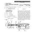
An autofocus system includes: an imaging unit Which cap
’
tures an image of an object formed by an optical system; an
Related U_s_ Application Data
_
_
_
autofocus portion Which performs focus adjustment of the
_
optical system on an autofocus area set in the image captured
(63) Continuation of application No. PCT/JP2012/050979,
by the imaging unit so that the Object Within the autofocus
?led on Jan‘ 18’ 2012 '
area comes into focus; anAF area tracking processing portion
,
(30)
,
,
,
,
Which performs tracking processing to set a predetermined
Forelgn Apphcatlon Prmnty Data
Jan 18 2011
'
(JP)
’
object Within the autofocus area as a target to be tracked,
2011008333
detect a presence area of the target to be tracked in an image
"""""""""""""""" "
neWly captured by the imaging unit and determine the pres
Publication Classi?cation
ence area as a neW autofocus area; a depth-of-?eld computing
portion Which calculates a depth of ?eld based on information
(51)
Int. Cl.
H04N 5/232
acquired from the optical system; and a control portion as
de?ned herein.
(2006.01)
1O
28
12
14
k
W VIEWFINDER 16
I
CAMERA
f/
ITEM“
2a I
I-ID VIDEO OUT
DOWN CONVERTER
HD _> SD
OUTPUTAF FRAME INFORMATION
30
20
58 d SCII
36
42
COMPUTING BOARD COMPUTING BOARD
I'D
I
VIDEO
ISAJSEER
2
TOUCH PANEL
CPU
62 SIGNAL
W
SIZE \fy
“HE 54
@52
\IRAM
[El/~56
.__;_p__, I
FACE
POSI'HON
66
I
DATA CARD
RAM
SHAPE of:
68
.
_.
AUTO I
LTRACK‘NG
SET
L
RELEASE
39
8
64
70
FLAME POSITION
'
74
J
AUTHENTICATION
38
MAIN
BOARD
a“
L
5 34
PATTiI'éIggAéggI-IING FACEpFéEéIééAéITION
DEcoDERI5
OUTPUT
TOUCH PANEL-
18
IMAGE PROCESSING UNIT ; 32
iIOPERATION PORTION
INCLUDING LCD
If» 46
INPUT VIDEO
II-Jw
H
V
J—
DEFAULT
~60
-
I
Patent Application Publication
Nov. 14, 2013 Sheet 2 0f 5
US 2013/0300917 A1
FIG. 2
j”
200
/
\/\204
AFAREA
IMAGING AREA
FIG. 3
66a
204 f/
‘
i
T
W
H———————L‘_ \J304
0
Z
I AF FRAME FIXED /~—\_/300
AUTOM
TRACK/km? /_\/ 302
Patent Application Publication
Nov. 14, 2013 Sheet 3 0f 5
US 2013/0300917 A1
FIG. 4
204
\
H--+-—————l
TRACKING OFF
Patent Application Publication
I
Nov. 14, 2013 Sheet 4 0f 5
START
US 2013/0300917 A1
I
I‘
310
Facejlag = false
_
I
S24
S12
/
II
MOVE THE FRAME
CAPTURE IMAGE
POSITION TO THE
CENTER
814
V
[J
RECEIVE THE DIAPHRAGM VALUE.
OBJECT DISTANCE AND FOCAL
DISTANCE FROM LENS
S16
/-/
CALCULATE THE DEPTH OF FIELD
l
M
322
,1
STOP TRACKING
A
820
DEPTH
NO
OF FIELD < 50% OF OBJECT
DISTANCE?
'
S26
Face_?ag = false?
S28
YES
HAS IT MOVED?
IS THERE
ANY PERSON DETECTED WITHIN
THE FRAME?
NO
Face_?ag = true
832
II
//
START TRACKING
II‘
S34
UPDATE THE FRAME POSITION
II:
EXECUTE AF
—__.___J
”
836
/”
YES
Patent Application Publication
US 2013/0300917 A1
Nov. 14, 2013 Sheet 5 0f 5
FIG. 6
I
START
I
S40
V
f)
READ THE DIAPHRAGM, OBJECT
DISTANCE AND FOCAL DISTANCE
842
II
r/
CALCULATE THE DEPTH OF FIELD
IS THE DEPTH OF
FIELD INFINITE?
S48
AF OFF
AF ON
Nov. 14, 2013
US 2013/0300917 A1
AUTOFOCUS SYSTEM
CROSS REFERENCE TO RELATED
APPLICATION
[0001] This is a continuation of International Application
No. PCT/JP2012/050979 ?led on Jan. 18, 2012, and claims
priority from Japanese Patent Application No. 2011-008333
because the automatic tracking function cannot be automati
cally sWitched on/off in accordance With the change in the
angle of vieW by zooming.
[0010]
The invention provides an autofocus system pro
vided With an automatic tracking function, in Which occur
rence of mistracking can be suppressed When the angle of
vieW is changed by zooming.
?led on Jan. 18, 2011, the entire disclosures of Which are
Means for Solving the Problem
incorporated herein by reference.
[0011]
An autofocus system according to the invention
TECHNICAL FIELD
includes:
[0012] an imaging unit Which captures an image of an
[0002] The present invention relates to an autofocus system
provided With an automatic tracking function of de?ning an
object formed by an optical system;
[0013] an autofocus portion Which performs focus adjust
object Within an autofocus (AF) area as an object to be tracked
ment of the optical system on an autofocus area set in the
and updating the AF area according to the position of the
object to be tracked.
the autofocus area comes into focus;
image captured by the imaging unit so that the object Within
BACKGROUND ART
[0014] an AF area tracking processing portion Which per
forms tracking processing to set a predetermined object
[0003] There is knoWn a television camera system for
broadcasting use or business use, provided With an autofocus
function of automatically focusing on an object Within a
presence area of the target to be tracked in an image neWly
speci?c imaging area. This type camera system generally
uses contrast-methodAF Which is performed by detecting the
height of contrast of a captured image and controlling the
focus of a capturing optical system to maximize (locally
maximize) the contrast.
[0004] As to focusing by AF, focusing is generally per
formed not on the entire screen of the captured image but on
an object Within an area (autofocus area) Which is a part of the
captured image. That is, in the contrast method, focus adjust
Within the autofocus area as a target to be tracked, detect a
captured by the imaging unit and determine the presence area
as a neW autofocus area;
[0015]
focus adjustment by the autofocus portion and the tracking
processing by the AF area tracking processing portion based
on the depth of ?eld calculated by the depth-of-?eld comput
ing portion.
ment is performed to maximize the contrast of the captured
image (object image) Within the autofocus area.
[0005] An autofocus system With an automatic tracking
a depth-of-?eld computing portion Which calculates
a depth of ?eld based on information acquired from the opti
cal system; and
[0016] a control portion Which controls execution of the
Advantageous Effects of Invention
[0017] According to the invention, it is possible to provide
to achieve the autofocus function. The autofocus system in
an autofocus system provided With an automatic tracking
function, in Which occurrence of mistracking can be sup
Patent Literature 1 uses an AF mode in Which either of a
pressed When the angle of vieW is changed by zooming.
function as shoWn in Patent Literature 1 is knoWn as a system
?xation mode to turn off the automatic tracking function and
a tracking mode to turn on the automatic tracking function is
selected by an operation of a user.
BRIEF DESCRIPTION OF DRAWINGS
[0018]
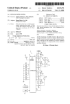
FIG. 1 A block diagram shoWing an overall con?gu
ration of a video camera system for explaining an autofocus
CITATION LIST
Patent Literature
[0006]
Patent Literature 1: Japanese Patent No. 4418344
SUMMARY OF INVENTION
Problem to be Solved by the Invention
[0007] Incidentally, in the autofocus system With the auto
matic tracking function, mistracking is apt to occur When the
angle of vieW is changed to a Wide angle side by zooming in
a state Where automatic tracking is performed. When the
angle of vieW is then changed from the Wide angle side to a
telephoto side, there is a possibility that another object than
the intended object Will be tracked.
[0008]
Moreover, even if an object Within an autofocus area
is in focus, there is a possibility that the object Will be out of
system according to an embodiment of the invention.
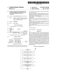
[0019] FIG. 2 A vieW for explaining an example of an
autofocus area in the autofocus system according to the
embodiment of the invention.
[0020] FIG. 3 A vieW shoWing an example of a screen
displayed on a touch panel-including liquid crystal display in
the video camera system in FIG. 1.
[0021] FIG. 4 A vieW shoWing an example of the screen
displayed on the LCD When automatic tracking is stopped.
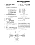
[0022] FIG. 5 A ?owchart shoWing a processing procedure
in an automatic tracking mode in the autofocus system
according to the embodiment of the invention.
[0023] FIG. 6A ?oW chart shoWing a processing procedure
of autofocus adjustment control in the autofocus system
according to the embodiment of the invention.
EMBODIMENTS FOR CARRYING OUT THE
INVENTION
focus When the angle of vieW is then changed by zooming.
[0024]
[0009] In the camera in Patent Literature 1, mistracking is
apt to occur When the angle of vieW is changed by zooming
automatic tracking function according to the invention Will be
described beloW With reference to the draWings.
An embodiment of an autofocus system With an
Nov. 14, 2013
US 2013/0300917 A1
[0025] FIG. 1 is a block diagram showing an overall con
?guration of a video camera system for explaining the auto
focus system according to the embodiment of the invention.
For example, this video camera system is used for capturing
an image With a television camera for broadcasting use or
business use.
[0026] As shoWn in FIG. 1, the video camera system 1
includes a television camera 10, an image processing unit 18
constituting an AP area tracking processing portion perform
ing automatic tracking, and anAF frame operation portion 20.
[0027] The television camera 10 includes a camera body 14
made of an HD camera corresponding to a high-de?nition
television (HD TV) system, and a lens device 12 having an
imaging lens (optical system) attached to a lens mount of the
camera body 14.
[0028] An image sensing device (for example, a CCD
image sensing device), a required signal processing circuit,
etc. are mounted in the camera body 14. An image formed by
the imaging lens of the lens device 12 is photoelectrically
converted by the image sensing device and then subjected to
required signal processing by the signal processing circuit, so
that the image is outputted as an HDTV-system video signal
(HDTV signal) to the outside from a video signal output
terminal, etc. of the camera body 14.
[0029]
A vieW?nder 16 is further mounted in the camera
body 14 so that each image captured by the television camera
10 is displayed on the vieW?nder 16. Various kinds of infor
mation other than the captured image is further displayed on
the view?nder 16. For example, an image (frame image)
indicating an AP frame Which is the contour of the currently
set autofocus area is displayed While superimposed on the
captured image.
[0030]
The lens device 12 has an imaging lens (Zoom lens)
attached to the lens mount of the camera body 14 so that an
image of an object 28 is formed on an imaging surface of an
image sensing device of the camera body 14 by the imaging
lens. Though not shoWn, movable portions for adjusting
imaging conditions such as a focus lens group, a Zoom lens
group, a diaphragm, etc. are provided as constituent elements
of the imaging lens. These movable portions are electrically
driven by a motor (servo mechanism). For example, the focus
lens group and the Zoom lens group move in an optical axis
direction so that the focus (object distance) is adjusted by the
movement of the focus lens group While the focal distance
(Zoom ratio) is adjusted by the movement of the Zoom lens
group.
[0031]
Incidentally, as long as at least the focus lens group
can be electrically driven, the other movable portions may be
driven only manually in the system concerned With autofocus
adjustment.
[0032]
An AF unit 40 and a lens CPU not shoWn, etc. are
further mounted in the lens device 12. The lens CPU generally
controls the lens device 12 as a Whole. The AP unit 40 is a
processing portion for acquiring information necessary for
a predetermined format. Incidentally, the video signal output
ted from the AF imaging circuit is a luminance signal.
[0034]
Object light incident on the image sensing device of
the camera body 14 is branched by a half mirror or the like
disposed on an optical path of the imaging lens, so that an
image of the branched object light is formed on the imaging
surface of the AF image sensing device. The imaging area and
the object distance (the distance to the object coming into
focus) in the AF image sensing device are formed to be
coincident With the imaging area and the object distance in the
image sensing device of the camera body 14, so that the object
image taken in by the AF image sensing device is coincident
With the object image taken in by the image sensing device of
the camera body 14. Incidentally, the imaging ranges of the
tWo image sensing devices do not need to be perfectly coin
cident With each other. For example, the imaging range of the
AF image sensing device may be a larger range including the
imaging range of the image sensing device of the camera
body 14.
[0035] The AP processing portion acquires a video signal
from the AF imaging circuit, and calculates a focus evaluation
value indicating the level of contrast of an object image Within
the autofocus area based on the video signal. For example,
after a high frequency component signal is extracted by a high
pass ?lter from the video signal obtained from the AF image
sensing device, a signal of an image of the autofocus area set
as Will be described later, among the high frequency compo
nent signal, is integrated scene by scene (frame by frame).
The integrated value obtained thus scene by scene indicates
the level of contrast of the image of the autofocus area. The
integrated value is given as a focus evaluation value to the lens
CPU.
[0036] The lens CPU acquires information of an AP frame
(AF frame information) indicating contour information (posi
tion, siZe, shape etc.) of the autofocus area from the image
processing unit 18 as Will be described later, and designates
the autofocus area designated by the AF frame information as
a target range for AF processing. The focus evaluation value
obtained based on the image (video signal) of the autofocus
area is acquired from the AF processing portion.
[0037] Whenever the video signal for one scene is acquired
thus from the AF imaging circuit (Whenever a focus evalua
tion value is obtained by theAF processing portion), the focus
evaluation value is acquired from the AF processing portion
and the focus lens group is controlled to maximiZe (locally
maximiZe) the acquired focus evaluation value, that is, to
maximiZe the contrast of the object image Within the autofo
cus area. For example, a mountain-climbing method is gen
erally knoWn as the focus lens group controlling method
based on the focus evaluation value. The focus lens group is
moved in a direction of increasing the focus evaluation value.
When a point at Which the focus evaluation value begins to
decrease is detected, the focus lens group is set at that posi
tion. In this manner, the object Within the autofocus area is
focus control (automatic focus adjustment) based on the auto
brought into focus automatically.
[0038] Although the aforementioned AF processing por
focus adjustment. Though not shoWn, an AP processing por
tion, an AP imaging circuit, etc. constitute the AF unit 40.
tion acquires a video signal from theAF image sensing device
[0033]
TheAF imaging circuit is disposed in the lens device
12 in order to acquire a video signal for AF processing. The
AP imaging circuit has an image sensing device (referred to
as AF image sensing device) such as a CCD image sensing
device, and a processing circuit Which outputs an output
signal of the AF image sensing device as a video signal With
mounted in the lens device 12 in order to calculate the focus
evaluation value, con?guration may be made so that the
aforementioned AF processing portion acquires a video sig
nal of each image captured by the image sensing device of the
camera body 14 from the camera body 14. In addition, any AF
unit may be used as long as the AF unit can automatically
focus on an object Within the autofocus area.
Nov. 14, 2013
US 2013/0300917 A1
[0039] Next, the autofocus area in the autofocus system
according to the embodiment of the invention Will be
described. FIG. 2 is a vieW showing an example of the auto
focus area in the autofocus system according to the embodi
ment of the invention. As shoWn in FIG. 2, an autofocus area
200 is set as a quadrilateral area With respect to an imaging
area 202 (or an imaging range) of the image sensing device in
the camera body 14. The contour of the autofocus area 200 is
indicated as anAF frame 204. In the autofocus system accord
ing to the embodiment of the invention, an object to be
imaged Within the autofocus area 200 (area Within the AF
tured image corresponding to one frame sequentially from the
video signal inputted from the camera body 14 and detecting
an object as a predetermined target to be tracked from the
captured image When automatic tracking processing is
executed. The image processing unit 18 determines the auto
focus area 200 so as to bring the object into focus by AP, and
then transmits information of the determined autofocus area
200 to the lens CPU of the lens device 12. Incidentally, the
con?guration and processing contents of the image process
ing unit 18 Will be described later.
[0046] The AP frame operation portion 20 is provided as a
device integrated With the image processing unit 18. A touch
frame 204) of the image sensing device is brought into focus.
[0040] Incidentally, this speci?cation is placed on the
panel-including liquid crystal display (LCD) 66 Which Will be
assumption that the autofocus area 200 relative to the imaging
area 202 is determined based on three factors, i.e. the position,
described later is con?gured to be detachable from the image
processing unit 18. Incidentally, the AF frame operation por
siZe and shape (aspect ratio) of the contour (AF frame 204) of
tion 20 may be provided in such a form that the AF frame
operation portion 20 is partially or entirely formed as a sepa
the autofocus area 200 and the autofocus area 200 is changed
When at least one of the three factors, i.e. the position, siZe and
shape of the AF frame 204 is changed.
[0041] In addition, the lens device 12 is connected to the
camera body 14 through a cable or directly so that various
information can be exchanged betWeen the lens device 12 and
the camera body 14 through serial communication interfaces
12a and 1411 provided respectively in the lens device 12 and
the camera body 14. In this manner, information of the AF
frame set currently in the AF unit 40 is also transmitted to the
camera body 14, and an image of the AF frame corresponding
to the position, siZe and shape of the AF frame set currently in
each video image displayed on the vieW?nder 16 by process
ing in the camera body 14 is displayed While superimposed on
the video image.
[0042] The image processing unit 18 is a processing portion
for designating the autofocus area (the position, siZe and
shape (aspect ratio) of the AF frame) set in the AF unit 40 of
the lens device 12 by manual operation or automatic tracking
processing Which Will be described later. For example, the
image processing unit 18 is received in a not-shoWn housing
and placed in a side portion of a barrel of the imaging lens of
the lens device 12, an outer Wall surface of the housing of the
camera body 14 etc. Incidentally, the position Where the
image processing unit 18 is placed in the lens device 12 or the
camera body 14 is not limited thereto but may be any other
arbitrary position. In addition, the image processing portion
18 may be disposed in a portion other than the lens device 12
or the camera body 14.
[0043]
The image processing unit 18 has an SCI 58. The
SCI 58 is connected to the lens device 12 so the SCI 58 can
exchange various signals With the lens CPU through the SCI
1211. In this manner, AF frame information for designating the
autofocus area 200 is given to the lens CPU of the lens device
12 from the image processing unit 18 so that the autofocus
area 200 in the AF unit 40 is set based on the AF frame
information.
[0044] In addition, a video input connector for importing a
video signal is provided in the image processing unit 18. A
video output connector of the camera body 14 is connected to
the video input connector through a doWn converter 46. In this
manner, an HDTV signal outputted from the video output
connector of the camera body 14 is converted (doWn-con
verted) into a standard television (NTSC (National Television
rate device from the image processing unit 18 and connected
to the image processing unit 18 by a cable etc.
[0047] The AP frame operation portion 20 is an operation
portion for mainly performing operation concerned With con
trol of the AF frame. The AP frame operation portion 20 is
provided With an operation member by Which an operator can
input an instruction of the autofocus area 200 by manual
operation, and an operation member by Which operation con
cerned With automatic tracking for automatically tracking a
desired object can be performed.
[0048] Although the details Will be omitted, the AF frame
operation portion 20 includes a position operation member 60
(for example, a j oystick or a trackball) for moving the position
of the autofocus area (the position of the AF frame) up, doWn,
left and right by user’s manual operation, a siZe operation
member 62 (for example, a knob) for changing the siZe of the
autofocus area (the siZe of the AF frame) by manual opera
tion, a shape operation member 64 (for example, a knob) for
changing the shape of the autofocus area (the shape of the AF
frame) by manual operation, a tracking start sWitch 68 for
issuing an instruction to start automatic tracking, and a track
ing stop sWitch 70 for issuing an instruction to stop automatic
tracking. The setting statuses of the operation members 60,
62, 64, 68 and 70 are read by a CPU 38 ofa main board 30 in
the imaging processing unit 18.
[0049] In addition, the touch panel-including liquid crystal
display (hereinafter referred to as “LCD”) is provided in the
AF frame operation portion 20. The LCD 66 is con?gured so
that setting of a mode concerned With automatic tracking etc.
can be inputted by touch operation (tap) on the LCD 66. An
image displayed on the LCD 66 can be sWitched suitably in
accordance With the setting contents by the CPU 38 of the
image processing unit 18.
[0050]
Incidentally, in the case Where only automatic track
ing based on an automatic tracking mode Which Will be
described later is performed in this embodiment, part or all of
the operation members 60, 62, 64, 68 and 70 of the AF frame
operation portion 20 can be dispensed With. In addition, the
LCD 66 can be also dispensed With. According to the auto
matic tracking mode Which Will be described later, automatic
tracking can be performed Without necessity of any operation
on the operation members 60, 62, 64, 68 and 70 and the LCD
66. The embodiment can be preferably applied to a small
System Committee) type video signal (SDTV signal) and
siZed camera such as a handy camera in Which it is dif?cult to
inputted to the image processing unit 18.
[0045] Although details Will be given later, the image pro
cessing unit 18 performs processing for fetching each cap
the space is not a problem and there is no in?uence on the
operability, con?guration can be made in such a manner that
spare a space for installing the AF frame operation device. If
Nov. 14, 2013
US 2013/0300917 A1
part or all of the operation members 60, 62, 64, 68 and 70 or
the LCD 66 are provided suitably so that the position of the
AF frame can be changed manually.
decoder 36 With an image signal generated by the CPU 38 and
outputs/displays the combined video signal to/on the LCD
66. In this manner, the video images captured by the televi
[0051] The con?guration and processing contents of the
image processing unit 18 Will be described beloW.
[0052] The image processing unit 18 includes a main board
30, a pattern matching process computing board 32, and a
face recognition process computing board 34. CPUs 38, 50
sion camera 10 can be displayed on the LCD 66 in the same
manner as on the vieW?nder 16 mounted in the camera body
14. At the same time, an image of the currently set autofocus
area, a menu screen (menu image) etc. on Which an input
operation is alloWed to be performed through the touch panel,
and 52 are mounted in the main board 30, the pattern match
etc. can be displayed on the LCD 66 While superimposed on
ing process computing board 32, and the face recognition
process computing board 34 respectively. Arithmetic pro
cessing is performed individually in each board. The CPUs
the captured video images. Incidentally, it is a matter of
course that only the image generated by the CPU 38 can be
displayed While not superimposed on the captured video
38, 50 and 52 are connected by a bus or a control line so that
images.
exchange of data, synchroniZation of arithmetic processing,
[0059] The RAM 39 is a memory Which temporarily stores
data used in arithmetic processing of the CPU 38.
etc. among the CPUs 38, 50 and 52 can be attained.
[0053]
Processing in the image processing unit 18 is gen
erally controlled in the main board 30. In addition to the CPU
38 for performing arithmetic processing, the SCI 58, a
decoder (A/D converter) 36, a super imposer 42, a RAM 39
[0060]
The pattern matching process computing board 32
and the face recognition process computing board 34 are
computing boards for individually performing pattern match
etc. are mounted in the main board 30.
ing and face detection/authentication process. The pattern
matching process computing board 32 and the face recogni
[0054] The SCI 58 is an interface circuit for performing
serial communication With the SCI 12a of the les device 12, as
described above. The SCI 58 transmits the AF frame infor
mation etc. to the lens device 12. In addition, the SCI 58
tion process computing board 34 are provided With the CPUs
50 and 52 Which perform arithmetic processing, VRAMs 54
and 56 Which temporarily store image data respectively, etc.
[0061] In addition, a slot (not shoWn) into Which a face
receives information including a diaphragm value, an object
authentication data card 74 is loaded as an external memory
such as an SD (Secure Digital) card, a USB memory, etc. is
distance, and a focal distance from the lens device 12.
[0055] The CPU 38 of the main board 30 performs arith
metic processing for calculating a depth of ?eld using the
diaphragm value, the object distance and the focal distance
acquired from the lens device 12, and control processing for
performing control to execute or stop automatic tracking
based on the calculated depth of ?eld. The arithmetic process
ing and the control processing may be performed by any one
of the main board 30, the pattern matching process computing
board 32 and the face recognition process computing board
34, or by a separately provided processing operation board
(not shoWn).
[0056]
The decoder 36 is a circuit for converting a video
provided in the image processing unit 18. When the face of a
speci?c person is detected by face recognition, recognition
data indicating the face of the speci?c person are stored in
advance in the face authentication data card 74. When the face
authentication data card 74 is loaded into the slot, the CPU 38
can read authentication data required for face recognition
from the face authentication data card 74.
[0062] Successively, control of the autofocus area per
formed by the image processing unit 18 con?gured as
described above Will be described in conjunction With pro
cessing concerned With display and operation of the LCD 66.
[0063]
FIG. 3 is a vieW shoWing an example of a screen
signal (SDTV signal) of video images of the television cam
displayed on the touch panel-including liquid crystal display
era 10 inputted to the image processing unit 18 from the doWn
converter 46 into data to Which digital processing can be
in the autofocus system according to the embodiment of the
invention.
[0064] As shoWn in FIG. 3, a menu screen (menu image)
including various buttons 300 and 302, and an AP frame 204
indicating an autofocus area 200 (see FIG. 2) set currently are
displayed on a screen 6611 of the LCD 66 While superimposed
on a video image captured by the television camera 10.
applied in the image processing unit 18. The decoder 36
performs A/D conversion processing etc. for converting an
analog SDTV signal into a video signal of digital data. The
video signal of video images outputted from the decoder 36 is
also sent to the pattern matching process computing board 32
and the face recognition process computing board 34 so that
the video images captured by the television camera 10 can be
acquired as captured images each corresponding to one frame
also in the pattern matching process computing board 32 and
the face recognition process computing board 34.
[0057]
Incidentally, the image processing unit 18 is pro
vided With a memory etc. Which is readable and Writable by
the CPU 38 and Which can be used suitably for storage of
Images superimposed on the captured video image, like the
various buttons 300 and 302 of the menu screen and the AF
frame 204, are generated by the CPU 38 of the main board 30
in the image processing unit 18 shoWn in FIG. 1. Those
images are displayed on the LCD 66 While superimposed on
the video image Which is captured by the television camera 10
and Which is outputted from the decoder 36 in the super
imposer 42. Incidentally, control concerned With display (dis
processing data etc. In addition, information about the posi
play contents) of the LCD 66 is performed by the CPU 38.
tion, siZe and shape of the autofocus area set in the AF frame
the autofocus area can be changed by a predetermined opera
[0065] In addition, an indicator 304 visually indicating an
angle of vieW of the lens based on information acquired from
the lens device 12 is provided in the screen 6611 of the LCD.
[0066] On the other hand, the LCD 66 is provided With a
touch panel. When a touch operation is performed so that the
tion of the AF frame operation portion 20 in accordance With
user’ s (cameraman’s) preference.
position information indicating the touched position (coordi
[0058]
The super imposer 42 is a circuit Which combines a
nates) is given to the CPU 38. In this manner, the position and
video signal of captured video images obtained from the
operation kind (tap, double-tap, etc.) of the touch operation
setting processing in the automatic tracking mode Which Will
be described later is stored in this memory. It is preferable that
the setting information about the position, siZe and shape of
screen 6611 of the LCD 66 is touched With a ?nger etc.,
US 2013/0300917 A1
Nov. 14, 2013
performed on the screen 6611 of the LCD 66 are detected by
by a user from the “object tracking mode”, the “face detection
the CPU 38. Processing in accordance With this operation is
executed by the CPU 38.
[0067] As basic operations in the screen 6611 of the LCD 66,
tracking mode”, the “face recognition tracking mode” and the
may be made so that a desired mode can be selected by a user
there are an operation for inputting an instruction assigned in
advance to each of the buttons 300 and 302, and an operation
from the “object tracking mode”, the “face detection tracking
mode”, the “face recognition tracking mode” and the “fully
for designating the autofocus area (area enclosed by the AF
automatic tracking mode” in the menu screen of the screen
66a ofthe LCD 66.
frame 204). The former operation is performed by tapping the
position of the button 300 or 302 With a ?nger etc. The latter
“fully automatic tracking mode”. Incidentally, con?guration
example, in such a manner that When a position to Which the
autofocus area is intended to be moved is tapped on the screen
[0074] The object tracking mode is a mode for tracking an
arbitrary object. At least part of the object set as the target to
be tracked is displayed to be enclosed in the AF frame. The
object tracking mode is a mode useful for capturing each
6611 of the LCD 66 on Which each captured video image is
image in horse racing broadcasting, car racing broadcasting,
operation for designating the autofocus area is performed, for
displayed, the autofocus area can be moved so that the posi
or the like for tracking an object other than a person’s face.
tion comes to the center. In addition, an apex or a side of the
When an operator designates the autofocus area so that an
AF frame 204 indicating the contour of the autofocus area can
be moved to a position to Where the touched apex or side is
image of an arbitrary object the operator Wants to set as the
target to be tracked is included in each of captured video
images in this mode, the object Within the autofocus area
enclosed by the AF frame is set as the target to be tracked. The
image of the target to be tracked is registered as a reference
pattern and a pattern matching process for detecting an image
range coincident With the reference pattern is performed on
dragged by a dragging operation for touching the apex or side
With a ?nger etc. and sliding the apex or side, so that the
position, siZe and shape of the autofocus area can be changed.
[0068] Incidentally, the position, siZe and shape of the auto
focus area canbe changed by operations of the position opera
tion member 60, the siZe operation member 62 and the shape
operation member 64 in the AF frame operation portion 20.
[0069]
To describe the menu screen (menu image) dis
played on the screen 6611 of the LCD 66, a ?xation mode
selection button 300 indicated as “AF frame ?xed”, and an
automatic tracking mode selection button 302 indicated as
“automatic tracking” are buttons for selecting an autofocus
control mode in FIG. 3. When one of these buttons 300 and
302 is tapped, a desired mode can be selected from the ?xa
tion mode and the automatic tracking mode.
[0070] The ?xation mode is a mode (manual mode) in
Which an operator designates an autofocus area (the position,
siZe and shape) by a manual operation and an AP frame is
displayed in the designated position so that the autofocus area
the sequentially obtained captured images in the CPU 50 of
the pattern matching process computing board 32. The CPU
38 of the main board 30 determines the range Where the
reference pattern is detected as a neW autofocus area, and
transmits information about the autofocus area to the lens
CPU of the lens device 12. Incidentally, When focus control
based on AF is not performed in the lens device 12 While
object automatic tracking starts (When it is not in the AF
mode), an instruction to start AF is also issued in conjunction
With the start of the object automatic tracking.
[0075] The face detection tracking mode is a mode for
tracking a face of an arbitrary person With the AF frame. A
face area of the person set as the target to be tracked is
displayed as the autofocus area to be enclosed With the AF
is ?xed. This ?xation mode is a mode useful for capturing
images in a neWs program for Which the camera is hardly
moved.
[0071] When the ?xation mode selection button 300 is
tapped on the screen 6611 of the LCD 66 in FIG. 3, the ?xation
mode is selected so that the CPU 38 mounted in the main
frame. The face detection tracking mode is a mode useful for
capturing images in a song program or the like for detecting
board 30 of the image processing unit 18 executes processing
When an operator designates a face image Which is to be set
as the target to be tracked from the detected face image, the
designated face image is set as the target to be tracked. Then,
of the ?xation mode.
[0072] That is, the CPU 38 determines the autofocus area
based on an operation on the screen 6611 of the LCD 66 for
changing the autofocus area or an operation on an operation
member (the position operation member 60, the siZe opera
tion member 62 or the shape operation member 64) for chang
ing the AF frame 204 provided in the AF frame operation 20
by a manual operation, as described above. Upon determina
tion of the autofocus area, the CPU 38 transmits AF frame
information indicating contour information of the autofocus
area to the lens CPU of the lens device 12 through the SCI 58.
[0073] The automatic tracking mode is a mode forperform
ing processing to set a predetermined object Within the auto
focus area, detect a presence area of the target to be tracked in
an image neWly captured by the imaging unit and determine
the presence area as a neW autofocus area. The automatic
tracking mode has a plurality of modes including an “object
tracking mode”, a “face detection tracking mode”, a “face
recognition tracking mode”, and a “fully automatic tracking
mode”. After the automatic tracking mode is selected on the
screen 6611 of the LCD 66, a desired mode is further selected
and tracking a person’s face. In this mode, ?rst, Well-knoWn
face detection processing for detecting a face image of an
arbitrary person from each captured image is performed in the
CPU 52 of the face recognition process computing board 34.
face detection processing is performed on sequentially
obtained captured images by the CPU 52 of the face recog
nition process computing board 34, and processing for iden
tifying the face image of the target to be tracked from the
detected face images is performed by the CPU 38 of the main
board 30. The CPU 38 of the main board 30 determines the
range of the detected face image of the target to be tracked as
a neW autofocus area and transmits information about the
autofocus area to the lens CPU of the lens device 12.
[0076] The face recognition tracking mode is a mode for
tracking a person’s face registered preliminarily as authenti
cation data With the AF frame. The face image of the person
registered as the target to be tracked is displayed as the auto
focus area to be enclosed With the AF frame. The face recog
nition tracking mode is a mode useful for capturing images in
a song program, sports broadcasting, or the like, in Which
each person to be imaged is determined preliminarily. In this
mode, authentication data of the face of the person set as the
target to be tracked is imported from the face authentication
Nov. 14, 2013
US 2013/0300917 A1
data card 74 loaded in the slot (not shown) shown in FIG. 1.
Face detection processing is performed in the CPU 52 of the
face recognition process computing board 34 is performed in
[0082] FIG. 5 is a How chart shoWing a processing proce
dure When the automatic tracking mode in the CPU of the
the same manner as in the face detection tracking mode, and
[0083] When the automatic tracking mode is selected by a
predetermined operation, ?rst, the CPU 38 of the main board
the face image of the target to be tracked is detected from
detected face images by a Well-knoWn face authentication
process using the authentication data. The CPU 38 of the
main board 30 determines the range of the face image
detected by the face recognition process as a neW autofocus
area, and transmits information about the autofocus area to
the lens CPU of the lens device 12.
[0077]
In the fully automatic tracking mode, Well-knoWn
face detection processing for detecting a face image of an
arbitrary person from captured images is performed in the
image processing unit is selected.
30 performs AF frame setting processing to set an autofocus
area at a predetermined initial position. A ?ag (Face_?ag)
indicating Whether face recognition is performed or not is set
to be false (step S10). In the AF frame setting processing, the
autofocus area in an imaging range (imaging area) is set based
on information about the position, siZe and shape of the
initially set autofocus area stored in the memory (not shoWn)
of the main board 30. AF frame information indicating the
information (the position, siZe and shape) of the thus set
CPU 52 of the face recognition process computing board 34
autofocus area is transmitted to the lens CPU of the lens
in the same manner as in the aforementioned face detection
device 12 through the SCI 58. In this manner, the autofocus
area is set in a range designated by the AF frame information
in the AF unit 40 of the lens device 12.
tracking mode. When the face image of the person is included
in the detected face image, the face image does not have to be
designated by an operator but can be automatically set as the
target to be tracked. When a plurality of face images are
included in the captured image on that occasion, a face image
Which is to be set as the target to be tracked is determined in
accordance With the siZe and position of the face. On the other
hand, When the face image of the person is not included in the
captured image, automatic tracking based on the aforemen
tioned object tracking mode is executed.
[0084] Successively, the CPU 52 of the face recognition
process computing board 34 imports image data of a captured
image corresponding to one frame from the decoder 36 (step
S12). The CPU 38 of the main board 30 is noti?ed of the
imported image data.
[0085] Next, the CPU 38 of the main board 30 acquires the
diaphragm value, the object distance and the focal distance
from the lens device 12 (step S14). In the step S14, the CPU
38 edits the acquired diaphragm value, object distance and
[0078] The video camera system 1 con?gured as described
above executes automatic tracking When the automatic track
focal distance as data linked to a corresponding face image,
ing mode is selected. When automatic tracking is performed,
and temporarily stores the edited diaphragm value, object
a depth of ?eld is calculated based on information obtained
from the lens device 12 and control is made to execute or stop
distance and focal distance in the RAM 39.
[0086] Next, the CPU 38 of the main board 30 executes
automatic tracking based on the depth of ?eld. In this manner,
mistracking can be avoided even When the angle of vieW for
arithmetic processing to calculate the depth of ?eld using the
data including the diaphragm value, the object distance and
the focal distance generated in the step S14 (step S16).
[0087] In the arithmetic processing in the step S16, the
depth of ?eld is calculated as in the folloWing expression (1).
In the expression (1 ), Lr is the rear depth of ?eld and Lf is the
front depth of ?eld.
capturing an image is changed to the Wide angle side by
Zooming of the lens device 12 at the time of execution of
automatic tracking.
[0079]
FIG. 4 shoWs an example of a screen displayed on
the LCD When automatic tracking is stopped. When an object
as a target to be tracked becomes small in the case Where
Zooming is set at a Wide angle as shoWn in FIG. 4, contrast
With a suf?cient level cannot be obtained in the set autofocus
area even if the autofocus area is set in accordance With the
expression (1)
Depth of FieldILr+Lf
[0088] The rear depth of ?eld Lr is calculated as in expres
sion (2). The front depth of ?eld Lf is calculated as in expres
based on the depth of ?eld. The autofocus area is changed to
sion (3). In the folloWing expressions, the focal distance of the
lens of the lens device 12 is f, the diaphragm value (f-number)
is FNo, the permissible circle of confusion is 6, and the object
a predetermined position (for example, the center of the imag
distance is L.
object. In such a case, the depth of ?eld is so deep that
execution of automatic tracking is automatically stopped
ing area) so that the AF frame 204 representing the contour of
the changed autofocus area is displayed While superimposed
6 - FNo - L2
on the screen 66a. In addition, a tracking stop mark 306
visually indicating the stop of automatic tracking is displayed
on the screen 66a. When automatic tracking is stopped, it is
arbitrary that either autofocus is performed or the lens is ?xed
to a previous focus position. As Will be described later, execu
tion or stop of autofocus adjustment may be controlled based
on the depth of ?eld.
[0080]
When automatic tracking is stopped, autofocus
adjustment is performed on an object in the predetermined
position of the imaging area (for example, the center of the
expression (2)
Rear Depth of Field Lr : m
.
6 - FNo - L2
expression (3)
Front Depth of Field Lf : m
[0089] When a blurring amount of an image is not higher
than a certain value in the condition that the image of an object
on the optical axis of the lens is formed on the imaging surface
(the imaging surface of the image sensing device), it appears
imaging area).
as if the lens focuses in a range around the point Where the
[0081] Successively, processing When the automatic track
ing mode performed by the image processing unit 18 is
object is brought into focus. A circle having the certain value
selectedWill be described. Incidentally, processing of the face
recognition tracking mode Will be described as folloWs by
Way of example.
of the blurring amount of the image on this occasion assumed
to be the diameter and the optical axis assumed to be the
center is a permissible circle of confusion. Incidentally, the
diameter of the permissible circle of confusion changes in
Nov. 14, 2013
US 2013/0300917 A1
accordance With the image size of the image sensing device,
pattern in the captured image has changed, determination in
the performance of the camera, usage conditions, etc.
[0090] In the range Where it appears as if the lens focuses,
the image forming range of the image forming surface side is
the determination processing results in YES.
[0098] When the determination in the step S28 results in
YES, the procedure goes to the processing of the step S34. In
referred to as the depth of focus. Incidentally, the depth d of
the case Where the determination in the step S28 results in
focus can be calculated based on d:26><FNo.
NO, the procedure goes to the processing of the step S36.
[0091]
Incidentally, the depth of ?eld has the folloWing
[0099]
According to the aforementioned video camera sys
properties.
tem 1, determination is made as to Whether an image of a
(i) The depth of ?eld is deeper as the diaphragm value is
person’s face is included in a captured image or not in the
automatic tracking mode. When determination is made that
larger.
(ii) The depth of ?eld is deeper as the focal distance is shorter.
(iii) The depth of ?eld is deeper as the object distance is
the image of the person’s face is included in the captured
longer.
image, the image of the person’s face is set as a target to be
tracked and automatic tracking based on face detection pro
(iv) The rear depth of ?eld is deeper than the front depth of
cessing is executed. When the angle of vieW is changed by
?eld.
Zooming on that occasion, determination is made as to
Whether execution of automatic tracking is alloWed or not
based on the depth of ?eld. When determination is made that
[0092] Successively to the step S16, the CPU 38 of the main
board 30 compares the depth of ?eld calculated in the step
S16 With a predetermined threshold to thereby determine
Whether the depth of ?eld is shalloWer than the threshold or
not (step S20). Here, assume that the threshold is 50% as long
as the object distance. When the depth of ?eld is shalloWer
than the threshold, the processing procedure goes to step S26.
When the depth of ?eld is not shalloWer than the threshold,
the processing procedure goes to step S22.
[0093] When the determination in the step S20 results in
NO, the CPU 38 determines that automatic tracking should be
execution of automatic tracking is not alloWed, automatic
tracking is automatically stopped. When determination is
made that execution of automatic tracking is alloWed, auto
matic tracking is executed.
[0100] In addition, the video camera system 1 can execute
automatic tracking, and control execution or stop of autofo
cus adjustment based on the depth of ?eld. The video camera
system 1 can control execution or stop of autofocus adjust
ment in parallel With the aforementioned control of automatic
stopped, and sets automatic tracking at OFF (step S22). The
tracking.
CPU 38 determines that the autofocus area is moved to a set
default position (for example, the center of the captured
[0101] FIG. 6 is a How chart shoWing a processing proce
dure When autofocus adjustment is controlled based on the
image), and transmits AF frame information indicating infor
depth of ?eld.
mation about the autofocus area to the lens CPU of the lens
[0102] When autofocus is executed, the CPU 38 of the main
board 30 brings the object into focus Within the autofocus area
set by the automatic tracking mode. Successively, the CPU 38
device 12 through the SCI 58 (step S24). When the processing
of the step S24 is completed, the procedure returns to the
processing of the step S10.
[0094] When the determination in the step S20 results in
YES, the CPU 38 determines Whether Face_?ag is “false” or
of the main board 30 acquires the diaphragm value, the object
distance and the focal distance from the lens device 12 (step
S40).
not (step S26). When Face_?ag is “false”, the processing
[0103]
procedure goes to step S30. When Face_?ag is “true”, the
processing procedure goes to step S28.
[0095] When the determination in step S26 results inYES,
the CPU 38 determines Whether the face image is detected
Within the captured image or not by the face detection pro
cessing in the step S14 (step S30). When the face image is
computing process for calculating the depth of ?eld by using
data including the diaphragm value, the object distance and
the focal distance generated in the step S40 (step S42).
detected Within the captured image, the processing procedure
goes to step S32. When the face image is not detected Within
the captured image, the processing procedure goes to step
Then, the CPU 38 of the main board 30 executes a
[0104] Successively to the step S42, the CPU 38 of the main
board 30 determines Whether the depth of ?eld calculated in
the step S40 is in?nite or not (step S44). Here, the fact that the
depth of ?eld is in?nite means that in?nity is included in the
depth of ?eld as a result of the computing.
[0105] When the determination in the step S44 is made that
range of the detected face image as a neW autofocus area, and
the depth of ?eld is in?nite, the processing procedure goes to
step S46. When the determination is made that the depth of
?eld is not in?nite, the processing procedure goes to step S48.
[0106] When the determination in the step S44 results in
YES, the CPU 38 sets autofocus adjustment at OFF (step
S22). The CPU 38 transmits information indicating stop of
transmits AF frame information indicating information about
autofocus adjustment to the AF unit 40 through the SCI 58
S36.
[0096] When the determination in the step S30 results in
YES, the CPU 38 sets Face_?ag at “true” (step S31). Succes
sively to the processing of the step S31, the CPU 38 starts
automatic tracking (step S32). The CPU 38 sets (updates) the
the autofocus area to the lens CPU of the lens device 12 (step
(step S46). When the processing of the step S46 is completed,
S34). The les device 12 executes autofocus adjustment in the
the procedure returns to the processing of the step S40.
[0107] When the determination in the step S44 results in
NO, the CPU 38 alloWs execution of autofocus adjustment
(step S48). The AP unit 40 executes autofocus adjustment in
the already set autofocus area (step S48). When the process
ing of the step S48 is completed, the procedure returns to the
processing of the step S40.
[0108] According to the aforementioned video camera sys
tem 1, When autofocus adjustment is performed, an object
neW autofocus area based on the AF frame information (step
S36). When the processing of the step S36 is completed, the
procedure returns to the processing of the step S12.
[0097] When the determination in the step S26 results in
NO, the CPU 38 determines Whether an image of a reference
pattern has moved or not, that is, Whether an image range in
Which the reference patter has been detected is different from
the currently set autofocus area or not (step S28). Incidentally,
even in the case Where the siZe of the image of the reference
Within a set autofocus area is brought into focus. When the
Nov. 14, 2013
US 2013/0300917 A1
angle of vieW is changed by Zooming on that occasion, deter
(2) An autofocus system described in the paragraph (1),
mination is made as to Whether execution of autofocus adjust
ment is allowed or not based on the depth of ?eld. When
Wherein:
[0120] the control portion makes control not to execute the
determination is made that execution of autofocus adjustment
tracking processing When the depth of ?eld is smaller than a
is not alloWed, autofocus adjustment is automatically
predetermined threshold.
stopped. In addition, When determination is made that execu
(3) An automatic system described in the paragraph (1) or (2),
tion of autofocus adjustment is alloWed, autofocus adjust
Wherein:
[0121] the control portion makes control not to execute the
ment is executed.
[0109]
In addition, according to the video camera system 1,
the SPU 38 of the main board 30 determines Whether execu
focus adjustment When the depth of ?eld is in?nite.
(4) An autofocus system according to any of the paragraphs
tion of at least one of automatic tracking and autofocus adjust
(1) through (3), Wherein:
ment is alloWed or not, based on the depth of ?eld. When
determination is made that the execution is not alloWed, con
trol is made to stop the execution. When control is made to
depth of ?eld based on information about diaphragm value,
object distance and focal distance obtained from the optical
[0122] the depth-of-?eld computing portion calculates the
automatically turn ON/OFF automatic tracking and autofo
cus adjustment, mistracking can be prevented from occurring
system.
in the folloWing case.
[0110] When there is an area in Which the lens does not
(1) through (4), Wherein:
focus in a captured image and there is a moving object in the
captured image and When su?icient contrast can be obtained
from an image of the object Within the autofocus area, control
(5) An autofocus system according to any of the paragraphs
[0123]
the AF area tracking processing portion sets a
human image Within the autofocus area as a target to be
tracked.
is made to turn ON automatic tracking and turn ON AF.
[0111] There may be a case Where the lens does not focus at
INDUSTRIAL APPLICABILITY
any position of the captured image and there is an object
Which moves in the imaging range of the captured image. In
[0124] The autofocus system according to the invention is
provided With an automatic tracking function capable of sup
pressing occurrence of mistracking When the angle of vieW is
such a case, it is assumed that execution of autofocus adjust
ment is not necessary because the depth of ?eld is in?nite so
changed by Zooming. Accordingly, the autofocus system is
that automatic tracking of the object is performed. In such a
case, automatic tracking is controlled to be ON and autofocus
adjustment is controlled to be OFF.
useful When it is applied to a digital camera, especially a
[0112]
ing apparatus, or the like.
[0125] The present application is based on Japanese Patent
Application No. 2011-8333 ?led on Jan. 18, 2011, the con
tents of Which are incorporated herein by reference.
In the case Where there is an area in Which the lens
does not focus in the captured image and the object as the
target to be tracked is too small, su?icient contrast cannot be
obtained from the image of the object in the range of the AF
area. Therefore, the accuracy of automatic tracking is loW
ered. In such a case, automatic tracking is controlled to be
OFF and autofocus adjustment is controlled to be ON.
[0113] In the case Where the lens does not focus in any
position of the captured image and the object as the target to
be tracked is too small, both automatic tracking and autofocus
adjustment are controlled to be OFF.
[0114]
In this speci?cation, the autofocus system is dis
closed as follows.
(1) An autofocus system including:
[0115]
an imaging unit Which captures an image of an
object formed by an optical system;
[0116] an autofocus portion Which performs focus adjust
ment of the optical system on an autofocus area set in the
image captured by the imaging unit so that the object Within
the autofocus area comes into focus;
[0117] an AP area tracking processing portion Which per
forms tracking processing to set a predetermined object
compact digital camera, a camera-including cellular phone, a
camera-including electronic apparatus, an endoscope imag
EXPLANATIONS OF REFERENCE SIGNS
[0126]
[0127]
[0128]
[0129]
[0130]
1 video camera system
10 television camera
12 lens device
14 camera body
16 vieW ?nder
[0131] 18 image processing unit
[0132] 20 AF frame operation portion
[0133]
[0134]
30 main board
40 AF unit
[0135] 32 pattern matching process computing board
[0136] 34 face recognition process computing board
[0137] 38, 50, 52 CPU
[0138] 66 liquid crystal display (LCD)
1. An autofocus system comprising:
Within the autofocus area as a target to be tracked, detect a
an imaging unit Which captures an image of an object
presence area of the target to be tracked in an image neWly
formed by an optical system;
an autofocus portion Which performs focus adjustment of
captured by the imaging unit and determine the presence area
as a neW autofocus area;
the optical system on an autofocus area set in the image
[0118]
a depth-of-?eld computing portion Which calculates
captured by the imaging unit so that the object Within the
a depth of ?eld based on information acquired from the opti
cal system; and
[0119] a control portion Which controls execution of the
an AP area tracking processing portion Which performs
tracking processing to set a predetermined object Within
autofocus area comes into focus;
focus adjustment by the autofocus portion and the tracking
processing by the AF area tracking processing portion based
on the depth of ?eld calculated by the depth-of-?eld comput
the autofocus area as a target to be tracked, detect a
ing portion.
presence area as a neW autofocus area;
presence area of the target to be tracked in an image
neWly captured by the imaging unit and determine the
Nov. 14, 2013
US 2013/0300917 A1
a depth-of-?eld computing portion Which calculates a
depth of ?eld based on information acquired from the
optical system; and
a control portion Which individually controls execution of
the focus adjustment by the autofocus portion and
execution of the tracking processing by the AF area
tracking processing portion based on the depth of ?eld
calculated by the depth-of-?eld computing portion.
2. The autofocus system as claimed in claim 1, Wherein the
control portion makes control not to execute the tracking
processing When the depth of ?eld is equal to or deeper than
a predetermined threshold.
3. The automatic system as claimed in claim 1, Wherein the
control portion makes control not to execute the focus adjust
ment When in?nity is included in the depth of ?eld.
4. The automatic system as claimed in claim 2, Wherein the
control portion makes control not to execute the focus adjust
ment When in?nity is included in the depth of ?eld.
5. The autofocus system as claimed in claim 1, Wherein the
depth-of-?eld computing portion calculates the depth of ?eld
based on information about diaphragm Value, object distance
and focal distance obtained from the optical system.
6. The autofocus system as claimed in claim 2, Wherein the
depth-of-?eld computing portion calculates the depth of ?eld
based on information about diaphragm Value, object distance
and focal distance obtained from the optical system.
7. The autofocus system as claimed in claim 3, Wherein the
depth-of-?eld computing portion calculates the depth of ?eld
based on information about diaphragm Value, object distance
and focal distance obtained from the optical system.
8. The autofocus system as claimed in claim 4, Wherein the
depth-of-?eld computing portion calculates the depth of ?eld
based on information about diaphragm Value, object distance
and focal distance obtained from the optical system.
9. The autofocus system as claimed in claim 1, Wherein the
AF area tracking processing portion sets a human image
Within the autofocus area as a target to be tracked.
10. The autofocus system as claimed in claim 2, Wherein
the AF area tracking processing portion sets a human image
Within the autofocus area as a target to be tracked.
11. The autofocus system as claimed in claim 3, Wherein
the AF area tracking processing portion sets a human image
Within the autofocus area as a target to be tracked.
12. The autofocus system as claimed in claim 4, Wherein
the AF area tracking processing portion sets a human image
Within the autofocus area as a target to be tracked.
13. The autofocus system as claimed in claim 5, Wherein
the AF area tracking processing portion sets a human image
Within the autofocus area as a target to be tracked.
14. The autofocus system as claimed in claim 6, Wherein
the AF area tracking processing portion sets a human image
Within the autofocus area as a target to be tracked.
15. The autofocus system as claimed in claim 7, Wherein
the AF area tracking processing portion sets a human image
Within the autofocus area as a target to be tracked.
16. The autofocus system as claimed in claim 8, Wherein
the AF area tracking processing portion sets a human image
Within the autofocus area as a target to be tracked.
*
*
*
*
*


