1
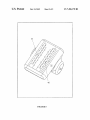
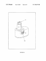
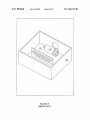
US007496178B2
(12) United States Patent
(10) Patent N0.2
Turner
(54)
US 7,496,178 B2
(45) Date of Patent:
PORTABLE X-RAY DEVICE
(56)
*Feb. 24, 2009
References Cited
U.S. PATENT DOCUMENTS
(75)
Inventor:
D. Clark Turner, Payson, UT (US)
3,728,457 A
4/1973 Lundin
Continued
(73) Assignee: AribeX, Inc., Orem, UT (U S)
(
)
FOREIGN PATENT DOCUMENTS
( * ) Notice:
Subject‘ to any disclaimer, the term ofthis
EP
0247758
12/1987
patent is extended or adjusted under 35
U.S.C. 154(b) by 395 days.
(Continued)
Tlhis patent is subject to a terminal dis-
OTHER PUBLICATIONS
c a1mer.
Fiorini, C.; Longoni, A.; MilaZZo, M.; Zaraga, F, In-situ, non-de
( 21 )
APP 1_ NO;
10/529 , 805
(22)
PCT Filed,
Feb 18 2005
'
(86) PCT No.:
§ 371 (0X1),
(2)’ (4) Date;
'
structive identi?cation of chemical elements by means ofportable
EDXRF spectrometer. Nuclear Science Symposium, 1998. Confer
ence Record. 1998 IEEE, v01. 1, Iss., 1998, pp. 375-380, v01. 1
’
(Abstract).
PCT/US2005/005712
(Continued)
Primary Examinerilrakli KiknadZe
(74) Attorney, Agent, or FirmiKenneth E. Horton; Kirton
Aug 1, 2005
and McConkie
(87)
PCT Pub. No.: WO2005/081956
(57)
ABSTRACT
PCT Pub. Date: Sep. 9, 2005
_
(65)
_
_
Portable X-ray devices and methods forusing such devices are
Pnor Pubhcatlon Data
Us 2007/0269010 A1
NOV 22 2007
'
.
(60)
(51)
’
loW-density insulating material containing a high-Z sub
.
stance. The devices can also have an integrated display com
Related U's' Apphcatlon Data
Provisional application No. 60/546,575, ?led on Feb.
20, 2004'
Int_ CL
H05G 1/10
(52)
(58)
described. The devices have an X-ray tube poWered by an
integrated poWer system. The X-ray tube is shielded With a
ponent. With these components, the siZe and Weight of the
X-ray devices can be reduced, and the portability of the
devices enhanced. Thus, the portable X-ray devices are espe
cially useful for applications Where portability is an important
feature such as in ?eld Work, remote operations, and mobile
(2006 01)
operations such nursing homes, home healthcare, teaching
'
US. Cl. ..................................... .. 378/ 101; 378/ 102
Field of Classi?cation Search ................. .. 378/98,
classrooms. This portability feature can be particularly useful
in multi_suite medical and dental o?ices Where a Single X_ray
device can be used in multiple of?ces instead of single using
378/98.2, 98.8, 101*104, 109*112, 119,
an X-ray device in each of?ce.
378/ 1 91
See application ?le for complete search history.
24 Claims, 9 Drawing Sheets
US 7,496,178 B2
Page 2
3,828,194
3,925,672
4,039,811
4,191,889
4,221,969
4,311,913
4,490,834
4,646,338
4,694,480
4,768,216
4,775,992
4,797,907
4,809,311
4,811,375
4,856,036
4,930,146
4,979,198
5,077,771
5,111,493
5,153,900
5,379,335
US. PATENT DOCUMENTS
Kastis, G.A.; Furenlid, L.R.; Wilson, D.W.; Peterson, T.E.; Barber,
H.B.; Barrett, H.H., Compact CT/SPECTsmall-animal imaging sys
A
A
A
A
A
A
A
A
A
A
A
A
A
A
A
A
A
A
A
A
A
tem, Nuclear Science, IEEE Transactions on, vol. 51, Iss. 1, Feb. 2004
pp. 63-67 (Abstract).
8/1974
12/1975
8/1977
3/1980
9/1980
1/1982
12/1984
2/1987
9/1987
8/1988
10/1988
1/1989
2/1989
3/1989
8/1989
5/1990
12/1990
12/1991
5/1992
10/1992
1/1995
Grasser
Soder et al.
Ennslin et al.
Cowell
Schmidt
Resnick et al.
Sudani
Skillicorn
Skillicorn
Harvey et al.
Resnick et al.
Anderton
Arai et al.
Klostermann
Malcolm et al.
Flakas et al.
Malcolm et al.
Skillicorn
Siedband
Nomikos et al.
Griesmer et a1.
5,442,677 A *
8/1995
Golden et al. ............. .. 378/102
5,631,943
5,708,694
6,038,287
6,205,200
5/1997
1/1998
3/2000
3/2001
Miles
Beyerlein et a1.
Miles
Boyer et al.
8/2001
GrodZins ................... .. 378/87
A
A
A
B1
6,282,260 B1 *
6,327,338 B1
6,459,767 B1
12/2001 Golovanivsky
10/2002 Boyer
6,661,876 B2
12/2003 Turner et al.
6,822,250 B2 *
11/2004
Korenev ................ .. 250/492.3
2003/0002627 A1
l/2003 Espinosa et al.
2003/0048877 A1
2003/0142788 A1
3/2003 Price et al.
7/2003 Cho et al.
2005/0018817 A1
2005/0053199 A1
2005/0213709 A1
1/2005 Oettinger et al.
3/2005 Miles
9/2005 Dinsmore et al.
FOREIGN PATENT DOCUMENTS
EP
EP
EP
JP
JP
JP
JP
W0
W0
W0
W0
W0
0488991
0524064
0784965
59-073897
62-246300
62-283600
03-225797
W0 92-04727
WO 95/20241
W0 96-05600
WO 2004047504
WO 2005008195
6/1992
1/1993
7/1997
4/1984
10/1987
12/1987
10/1991
3/1992
7/1995
2/1996
6/2004
1/2005
Shrivastave, P.; O’Connell, S.; Whitley, A., Handheld x-ray?uores
cence.‘ practical application as a screening tool to detect the presence
of environmentally-sensitive substances in electronic equipment,
Electronics and the Environment, 2005. Proceedings of the 2005
IEEE International Symposium on, vol., Iss., May 16-19, 2005 pp.
157-162 (Abstract).
Idrissi, M.M.; Dudemaine, M., Viladrosa, R.; Robert, E.;
Cachoncinlle, C.; Pouvesle, J .M., Experimental study and develop
ment of a single focus burst X-ray ?ash, Pulsed Power Conference,
2003. Digest of Technical Papers. PPC-2003. 14th IEEE Interna
tional, vol. 2, Iss., Jun. 15-18, 2003 pp. 752-755 vol. 2 (Abstract).
Maur, F., X-ray inspection for electronic packaging latest develop
ments, Electronic Packaging Technology Proceedings, 2003. ICEPT
2003. Fifth International Conference on, vol., Iss., Oct. 28-30, 2003
pp. 235-239 (Abstract).
Matsumoto, T.; Mimura, H., X-ray radiography system using graph
ite-nano?bers cold cathode, Vacuum Microelectronics Conference,
2003. Technical Digest ofthe 16th International, vol., Iss., Jul. 7-11,
2003 pp. 301-302 (Abstract).
Kastis, G.A.; Furenlid, L.R.; Wilson, D.W.; Peterson, T.E.; Barber,
H.B.; Barrett, H.H., Compact CT/SPECTsmall-animal imaging sys
tem Nuclear Science Symposium Conference Record, 2002 IEEE,
vol. 2, Iss., Nov. 10-16, 2002 pp. 797-801 vol. 2 (Abstract).
Bertolucci, E.; Boerkamp, T.; Maiorino, M., Mettivier, G.; Montesi,
M.C.; Russo, P., Portable system for imaging of/spl alpha/, /spl beta/
and X-ray sources with silicon pixel detectors and Medipix 1 read
out, Nuclear Science Symposium Conference Record, 2001 IEEE,
vol. 2, Iss., Nov. 4-10, 2001 pp. 709-713 vol. 2 (Abstract).
Longoni, A.; Fiorini, C.; GuaZZoni, C.; Gianoncelli, A.; Struder, L.;
Soltau, H.; Lechner, P.; Bjeoumikhov, A.; SchmalZ, J .; Langhoff, N.;
Wedell, R.; Kolarik, V., A new HP spectrometer based on a ring
shaped multi-element Silicon Drift Detector and on X-ray capillary
optics, Nuclear Science Symposium Conference Record, 2001 IEEE,
vol. 2, Iss., Nov. 4-10, 2001, pp. 897-901 vol. 2 (Abstract).
Shirochin, L.A.; Fursey, G.N., High-power soft X-ray tube with an
explosive emission cathode, Discharges and Electrical Insulation in
Vacuum, 1998. Proceedings ISDEIV. XVIIIth International Sympo
sium on, vol. 2, Iss., Aug. 17-21, 1998, pp. 672-674 vol. 2 (Abstract).
Fursey, G.N., Shirochin, L.A., Explosive emission phenomenon and
portable X-ray tubes, Vacuum Microelectronics Conference, 1998,
Eleventh International, vol., Iss., Jul. 19-24, 1998, pp. 142-143
(Abstract).
Takano, H.; Hatakeyama, T.; Sun, J.M., Laknath, K.G.D.; Nakaoka,
M., Feasible characteristic evaluations of resonant PWM inverter
linked DC-DC power converter using high-voltage transformer
parasitic circuit components, Power Electronics and Variable Speed
Drives, 1996. Sixth International Conference on (Conf. Publ. No.
OTHER PUBLICATIONS
Mesyats, G.A.; Shpak, V.G.; Yalandin, M.I.; Shunailov, S.A.
RADAN-EXPER T portable high-current accelerator, Pulsed Power
Conference, 1995. Digest of Technical Papers. Tenth IEEE Interna
tional, vol. 1, Iss., Jul. 3-6, 1995, pp. 539-543 vol. 1 (Abstract).
Fiorini, C.; Longoni, A. In-situ, non-destructive identi?cation of
chemical elements by means of portable EDXRF spectrometer,
Nuclear Science, IEEE Transactions on, vol. 46, Iss. 6, Dec. 1999 pp.
429), vol., Iss., Sep. 23-25, 1996 pp. 525-533.
ShirouZu, S.; Inoue, S., A new type X-ray instant camera, Nuclear
Science, IEEE Transactions on, vol. 39, Iss.5, Oct. 1992 pp. 1528
1531 (Abstract).
Sudarkin, A.N.; Ivanov, O.P.; Stepanov, V.E.;Volkovich, A.G.; Turin,
A.S.; Danilovich, A.S.; Rybakov, D.D.; Urutskoev, L.I., High-energy
radiation visualizer (HERV): a new system for imaging in X-ray and
gamma-ray emission regions, Nuclear Science, IEEE Transactions
2011-2016 (Abstract).
on, vol. 43, Iss.4, Aug. 1996, pp. 2427-2433 (Abstract).
Bertolucci, E.; Boerkamp, T.; Maiorino, M., Mettivier, G.; Montesi,
M.C.; Russo, P. Portable system for imaging of/spl alpha/, and X-ray
Longoni, A.; Fiorini, C.; GuaZZoni, C.; Gianoncelli, A.; Struder, L.;
Soltau, H.; Lechner, P.; Bjeoumikhov, A.; SchmalZ, J .; Langhoff, N.;
sources with silicon pixel detectors and Medipix] readout, Nuclear
Science, IEEE Transactions on, vol. 49, Iss. 4, Aug. 2002 pp. 1845
Wedell, R., A new XRF spectrometer based on a ring-shaped multi
1850 (Abstract).
Mesyats, G.A.; Korovin, S.D.; Rostov, V.V.; Shpak, V.G.; Yalandin,
MI, The RADAN series of compact pulsed power Generators and
their applications, Proceedings ofthe IEEE, vol. 92, Iss. 7, Jul. 2004
pp. 1166-1179 (Abstract).
element silicon drift detector and on X-ray capillary optics, Nuclear
Science, IEEE Transactions on, vol. 49, Iss.3, Jun. 2002, pp. 1001
1005 (Abstract).
Sinha, N.;Yeow, J .T.-W., Carbon nanotubes for biomedical applica
tions, NanoBioscience, IEEE Transactions on, vol. 4, Iss.2, Jun.
2005, pp. 180-195 (Abstract).
US 7,496,178 B2
Page 3
145 (Abstract).
Fry et al., Recent developments in electronic radiography at Los
Alamos, Proc. SPIE vol. 3769, p. 111-123, Penetrating Radiation
Systems and Applications, Oct. 1999. (Abstract).
Smith, et al., Evaluation of a CMOS image detectorfor low-cost and
power medical x-ray imaging applications, Proc. SPIE vol. 3659, p.
Chuvatin, AS.; Rudakov, L.I.; Velikovich, AL.; Davis, J.; Oreshkin,
952-961, Medical Imaging 1999, May 1999. (Abstract).
Kidd, R.; RabinowitZ, P.; Garrison, L.; Meyer, A; Adamson, A;
AurouX, C.; Baldauf, J .; Clement, B.; Palmer, A; Taylor, E.; Graham,
A, The Ocean Drilling Program III.‘ The shipboard laboratories on
“JOIDESResolution ”, OCEANS, vol. 17, Iss., Nov. 1985, pp. 133
V.I. , Heating ofon-axis plasma heatingfor keVX-rayproduction with
Z-pinches, Plasma Science, IEEE Transactions on, vol. 33, Iss.2, Apr.
2005, pp. 739-751 (Abstract).
Borisov et al., Ultrabright Multikilovolt Coherent Tunable X-Ray
Source at ~ 2. 71*293 Afor Biological Microimaging, 2004, Ameri
can Institute of Physics 0-7354-0195-0. (Abstract).
Momose et al., X-Ray TalbotInterferometryfor Medical PhaseImag
ing, 2004 American Institute of Physics 0-73 54-0195-0 (Abstract).
Sasaki et al., Protein Crystallography Beam Line at MIRRORCLE,
2004 American Institute of Physics 0-7354-0195-0. (Abstract).
Spartiotis et al., Novel direct digital modular x-ray device and system,
Proc. SPIE vol. 3336, p. 529-536, Medical Imaging 1998, Jul. 1998.
(Abstract).
Boyer et al., Pulsed hard x-ray sourcefor nondestructive testing and
medical imaging, Proc. SPIE vol. 3154, p. 16-26, Coherent Electron
Beam X-Ray Sources: Techniques and Applications, Oct. 1997.
(Abstract).
Xiang et al., New type ofx-ray-Wafer image intensi?er with CsI-CsI/
MCP photocathodes.‘ its design and assessment, Proc. SPIE vol.
1982, p. 230-235, Photoelectronic Detection and Imaging: Technol
Hirai, Novel Edge-Enhanced X-Ray Imaging Utilizing Mirrorcle,
ogy and Applications ’93, Apr. 1993. (Abstract).
Kutlubay et al., Cost-e?ective, high-resolution, portable digital x-ray
2004 American Institute of Physics 0-7354-0195-0. (Abstract).
imager, Proc. SPIE vol. 2432, p. 554-562, Medical Imaging 1995,
HironariYamada, Features ofthe portable synchrotrons named MIR
May 1995. (Abstract).
RORCLE, 2004 American Institute of Physics 0-7354-0195-0.
Seely et al., Dual-Energy Bone Densitometry Using a Single 100 NS
X-Ray Pulse Medical Physics, vol. 25, Oct. 1998 (Abstract).
Pi orek, Stanislaw, Field-Porta ble X-Ray Fluorescence Spectrometry.‘
Past, Present, and Future, MetoreX, Inc., Princeton, New Jersey, Mar.
1997. (Abstract).
(Abstract).
Hironari Yamada, The Synchrotron Light Life Science Center
Granted by the MEXT 21 St Century COE Program, 2004 American
Institute of Physics 0-7354-0195-0. (Abstract).
Hirai et al., Novel Edge-Enhanced X-ray Imaging by MIRRORCLE,
“DentalEZ Portable HDX Intraoral X-ray,” User’s Manual, Flow
Yue et al., Generation of continuous and pulsed diagnostic imaging
X-ray Inc., Mar. 2000 (Abstract).
Stumbo et al., Direct Analysis of Molybdenum Target Generated
X-ray Spectra with a Portable Device, Medical Physics, Oct. 2004,
x-ray radiation using a carbon-nanotube-based?eld-emission cath
vol. 31 Issue 10, pp. 2763-2770.
2004 American Institute of Physics 0-7354-0195-0.
ode, Applied Physics Letters, vol. 81, No. 2, Jul. 8, 2002. (Abstract).
Wang et al., Fast Reconstruction for Uncontained Cone-Beam
Moreno et al., Small-Chamber 4. 7 la] Plasma Focusfor Applications,
2001 American Institute of Physics 1-56396-999-8/01 (Abstract).
Boyer et al., Portable hard x-ray source for nondestructive testing
and medical imaging, Review of Scienti?c Instruments vol. 69, No. 6,
Jun. 1998. (Abstract).
Mikerov et al., Prospects offast neutron radiography based on por
table neutron generators, Proc. SPIE vol. 4142, p. 74-80, Penetrating
Tomosynthesis, Proceedings of SPIE, May 2004, vol. 5368, pp. 930
938 (Abstract).
Alexander Sasov, Desktop X-Ray Micro-CT Instruments, Proceed
ings of SPIE, Jan. 2002, vol. 4053, pp. 282-290 (Abstract).
Schewe et al., A Room-Based Diagnostic Imaging System for Mea
surement ofPatientSetup, Medical Physics, Dec. 1998, vol. 25, Issue
Radiation Systems and Applications II, Dec. 2000. (Abstract).
* cited by examiner
12, pp. 2385-2387.
US. Patent
Feb. 24, 2009
Sheet 1 of9
FIGURE 1
US 7,496,178 B2
US. Patent
Feb. 24, 2009
Sheet 2 of9
US 7,496,178 B2
10
FIGURE 2
US. Patent
Feb. 24, 2009
Sheet 3 of9
FIGURE 3
US 7,496,178 B2
US. Patent
Feb. 24, 2009
Sheet 4 of9
FIGURE 4
US 7,496,178 B2
US. Patent
Feb. 24, 2009
Sheet 5 of9
FIGURE 5
US 7,496,178 B2
US. Patent
Feb. 24, 2009
Sheet 6 of9
FIGURE 6
US 7,496,178 B2
US. Patent
Feb. 24, 2009
Sheet 7 of9
43a
FIGURE 7
US 7,496,178 B2
US. Patent
Feb. 24, 2009
Sheet 8 of9
FIGURE 8
US 7,496,178 B2
US. Patent
Feb. 24, 2009
Sheet 9 of9
FIGURE 9
(PRIOR ART)
US 7,496,178 B2
US 7,496,178 B2
1
2
PORTABLE X-RAY DEVICE
increases the siZe of the device and the number of system
components, and consequently decreases the portability of
the device.
CROSS-REFERENCE TO RELATED
APPLICATION
SUMMARY OF THE INVENTION
This application claims priority of US. Patent Application
The invention relates to portable x-ray devices and meth
ods for using such devices. The devices have an x-ray tube
Ser. No. 60/546,575, ?led on Feb. 20, 2004, the entire disclo
sure of Which is incorporated herein by reference.
poWered by an integrated poWer system. The x-ray tube is
shielded With a loW-density insulating material containing a
FIELD OF THE INVENTION
high-Z substance. The devices can also have an integrated
The invention generally relates to x-ray devices and meth
ods for using the same. More particularly, the invention
relates to x-ray tubes used in x-rays devices. Even more
display component. With these components, the siZe and
Weight of the x-ray devices can be reduced, and the portability
of the devices enhanced. Thus, the portable x-ray devices are
especially useful for applications Where portability is an
important feature such as in ?eld Work, remote operations,
particularly, the invention relates to portable x-ray devices
that contain an integrated poWer system, methods for using
teaching classrooms. This portability feature can be particu
such portable x-ray devices, and systems containing such
portable x-ray devices.
and mobile operations such nursing homes, home healthcare,
20
larly useful in multi-suite medical and dental of?ces Where a
single x-ray device can be used in multiple of?ces instead of
single using an x-ray device in each of?ce.
BACKGROUND OF THE INVENTION
BRIEF DESCRIPTION OF THE DRAWINGS
Typical x-ray tubes and x-ray devices (device containing
x-ray tubes) have been knoWn and used for some time. Unfor
25
tunately, they are usually bulky and are poWered by heavy,
high-voltage poWer supplies that restrict mobility. As Well,
they are often dif?cult and time-consuming to use. In many
instances, a sample for analysis must be sent to an off-site
The folloWing description of the invention can be under
stood in light of the Figures, in Which:
FIGS. 1-2 depict the x-ray device in one aspect of the
invention;
FIG. 3 depicts the x-ray device in another aspect of the
30
laboratory for analysis by the x-ray device.
invention;
These limitations can be very inconvenient for many popu
lar uses of x-ray devices containing them. Such uses include
invention;
FIG. 4 depicts the x-ray device in another aspect of the
x-ray ?uorescence @(RF) of soil, Water, metals, ores, Well
bores, etc., as Well as diffraction and plating thickness mea
35
surements. Typical x-ray imaging applications require the
sample to be imaged to be brought to the x-ray device. These
limitations have led to an increased interest in making x-ray
devices portable. See, for example, US. Pat. Nos. 6,661,876,
6,459,767, 6,038,287, and 6,205,200; US. Published Patent
40
con?guration.
FIGS. 1-9 illustrate speci?c aspects of the invention and are
a part of the speci?cation. In the Figures, the thickness and
45
ence.
Many of these existing designs increase the portability of
the same component. Together With the folloWing descrip
tion, the Figures demonstrate and explain the principles of the
invention.
50
DETAILED DESCRIPTION OF THE INVENTION
the portable designs, especially the XRF systems, have inter
nal or “integrated” poWer supplies, they don’t have the high
The folloWing description provides speci?c details in order
x-ray tube current load that is often necessary for x-ray imag
ing. For example, energy-dispersive XRF typically requires
55
x-ray beam currents of less than 1 milliampere While x-ray
imaging typically requires greater than about 2 milliamperes.
Third, high-quality imaging displays for displaying the
results of the x-ray analysis are not present. Finally, the radia
tion shielding for the x-ray tubes usually comprises lead,
Which is quite heavy and limits the portability of the device.
the image display component external to the chassis or hous
ing containing the x-ray tube. Such a con?guration, hoWever,
to provide a thorough understanding of the invention. The
skilled artisan, hoWever, Would understand that the invention
can be practiced Without employing these speci?c details.
Indeed, the invention can be practiced by modifying the illus
trated method and resulting product and can be used in con
junction With apparatus and techniques conventionally used
60
in the industry. While the invention is described for use in
x-ray imaging for dental purposes, it could be used in other
medical applications such as medical imaging, veterinary,
A further limitation on design of the increased portability is
the image collection and display components. Many of the
portable designs have the image collection component and
con?guration of components may be exaggerated for clarity.
The same reference numerals in different draWings represent
x-ray devices. At the same time, hoWever, these designs are
limited for several reasons. First, most of the designs are not
truly portable since they have an external poWer source (i.e.,
require utility-supplied line voltage). Second, While some of
aspect of the invention; and
FIG. 9 depicts a conventional x-ray tube in a conventional
Applications 2003/0048877, 2003/0002627, and 2003/
0142788; and European Patent Nos. EP0946082,
EP0524064, EP0247758, EP0784965, and EP0488991; the
entire disclosures of Which are incorporated herein by refer
FIG. 5 depicts the x-ray tube and poWer supply of the x-ray
device in one aspect of the invention;
FIGS. 6-7 depict the poWer source of the x-ray device and
method for connecting the poWer source to the x-ray device in
one aspect of the invention;
FIG. 8 depicts the x-ray tube of the x-ray device in one
and bone densitometry. As Well, it could be used for non
dental and non-medical applications such as industrial imag
65
ing, metal fatigue inspections, Weld-inspection for cracks/
voids and pipes, for security inspections alloWing random
inspection of parcels and carry-on baggage, and the like.
US 7,496,178 B2
3
4
As described above, the invention includes a portable x-ray
device that is used primarily for remote and/or applications,
including in multi-suite locations. The x-ray device can be
designed to be either handheld or temporarily ?xed to a given
location, such as a tripod-mount operation. As Well, the inven
tion could be mounted on any other semi-stable apparatus,
version means converts the initial voltage supplied by the
poWer source 40 to a converted voltage that is provided to the
poWer supply 34. The conversion means generally converts
the 14.4V (or similar voltage) provided by the poWer source
5
40 to a voltage ranging from about 80 to about 200V. In one
such as an articulating arm or C-arm as commonly used in
aspect of the invention, the initial voltage is converted to a
converted voltage of about 100V. Any conversion means
radiology applications and described in the publications men
knoWn in the art that operates in this manner can be used in the
tioned above. The x-ray device is portable in that it can be
transported by hand carrying it from one location to a second
invention, including the poWer management boards 36.
10
location Without support by any mechanical apparatus. Most
importantly, because of its integrated poWer system, the loca
The conversion means is electrically connected to the
poWer supply 34. The poWer supply 34 steps up the converted
voltage (i.e., the 100V) provided by the conversion means to
tion of use can be independent of any external ?xed poWer
a voltage that can be used by the x-ray tube 30. The poWer
source, such as utility-supplied AC voltage commonly avail
produced by the poWer supply 34 and input into the x-ray tube
able in the home or o?ice. This independence from external
poWer source is a de?ning feature of the portable x-ray device
described above.
As shoWn in FIGS. 1-2, the x-ray device 10 of the invention
contains a housing or chassis 20 to contain all the internal
components of the device. The housing 20 encloses an x-ray
tube 30 for producing the x-rays. The x-ray device 10 contains
a poWer system (including poWer source 40) to provide poWer
for the device 10 and means for sensing the x-rays, such as
30 via connection 35 (shoWn in FIG. 8) depends on the poWer
needed to operate the x-ray tube, and the maximum poWer
available from the poWer source. Generally, the poWer pro
vided by the poWer supply 34 to the x-ray tube 30 can range
from about 20 to about 150 kV. Typically, this poWer provided
by the poWer supply can range from about 40 kV to about 100
kV.
In one aspect of the invention, the poWer provided by the
20
?lm, CCD sensors, or imaging plates (not shoWn). The x-ray
device 10 also contains means for displaying the results of the
25
analysis such as an integrated image display screen 60 (shoWn
in FIG. 4); control means such as controller 70; and radiation
shielding 80 to shield the operator of the device from back
scattered radiation from the sample. The x-ray device 10 also
contains any other components knoWn in the art for ef?cient
from the poWer source, and the number of electron-acceler
ating grids in the x-ray tube. In one aspect of the invention, the
30
operation (such as x-ray collimator 32), including those com
ponents described in the documents mentioned above.
The x-ray device 10 contains a unique system for providing
poWer to the x-ray device. The poWer system of the x-ray
device comprises a poWer source 40, poWer supply 34, and
depends on the number of individual poWer supplies used, the
35
40
battery pack. The poWer source can be recharged by any
suitable means, such as by connection to an appropriate volt
age When using batteries that are re-chargeable.
cal connection means can be any of those knoWn in the art. As
depicted in FIG. 6, the electrical connection means can com
prise an extension member 41 With an electrical connector 42
contained in an upper portion thereof. The mechanical con
nection means comprises a release mechanism 43a.
45
range from about 20 kV to about 50 kV. In one aspect of the
invention, the poWer provided by each individual poWer sup
ply (When there are 2) is about +35 kV and —35 kV. In this
embodiment, the +35 kV is attached to the anode of the x-ray
tube and the —35 kV is attached to the cathode of the x-ray
tube. A ?lament transformer is included in the cathode poWer
supply to provide current to the x-ray tube ?lament and gen
erate an electron beam at the cathode of the tube. The total
poWer produced by the poWer supply is the therefore sum of
the individual anode poWer supply and the individual cathode
50
poWer supply.
When such individual loW voltage poWer supplies are used,
the x-ray tube 30 of the invention becomes more portable.
As shoWn in FIG. 7, the x-ray device 10 contains a locking
mechanism 43b. To connect the poWer source 40 to the x-ray
heat-dissipating capability of the x-ray tube. Generally, the
poWer supplied by each individual poWer supply is the total
poWer needed to operate the x-ray tube divided by the number
of individual poWer supplies. For example, the poWer pro
vided by each individual poWer supply (When there are 2) can
supply the desired amount of poWer, yet ?t Within the space
limitations of the x-ray device. In one aspect of the invention,
In one aspect of the invention, the poWer source 40 is
removable from the remainder of the x-ray device 10. In this
aspect of the invention, the poWer source 40 comprises
mechanical and electrical means for connecting the poWer
source 40 to the x-ray device 10. The electrical and mechani
plurality of individual poWer supplies is tWo (as represented
in FIG. 5 by 45, 46) Where 45 supplies positive voltage to the
anode and 46 supplies negative voltage to the cathode.
The poWer provided by each individual poWer supply
maximum poWer available from the poWer source, and the
conversion means. The poWer source 40 used in the x-ray
device of the invention can be any knoWn in the art that can
the poWer source comprises a battery, such as a 14.4V NiCd
poWer supply is provided by a plurality of individual poWer
supplies. The number of individual poWer supplies used
depends on the voltage needed for the x-ray tube, the space
needed for the poWer supply 34, the total poWer available
55
device 10, the poWer source 40 is gently pushed into the
Conventional x-ray tubes operate at much higher voltages in
the range of 70 kV and higher. Because of these high voltages,
and the need for the high voltage standoff, the conventional
x-ray tube 300 is often encased in insulating oil 302 (or a
bottom of the handle 15 of the x-ray device 10. When com
similar material) Within a liquid-tight case 306 as shoWn in
pletely connected, the electrical connector 42 connects With
the internal electronics of the x-ray device 10. The locking
mechanism 43b is automatically engaged to retain the poWer
FIG. 9. The oil 302 also has the advantage of dissipating the
high temperatures that existed during operation. By splitting
the needed operation voltage into 2 (or more) individual
poWer supplies, the individual poWer supplies only need to
provide (and also stand off) half of the higher voltage.
source 40 connected to the x-ray device 10 in this position. To
remove the poWer source 40, the release mechanism 43a is
actuated to unlock the locking mechanism 43b, and the poWer
source 40 can be gently slid out from the handle 15.
The poWer source 40 is electrically connected to the con
version means using any connection means knoWn in the art,
including those described in the publications above. The con
65
With these loWer voltages, the x-ray tube 30 of the inven
tion can be encapsulated in materials other than high-density
oil. These other materials need only insulate proportionately
to the reduced voltage, i.e., these other materials need only
insulate half as much as oil since the voltage produced is
US 7,496,178 B2
5
6
about half of that conventionally used. Any knoWn material
that can insulate in this manner can be used in the invention,
means (such as controller 76) is external to the device and is
connected to remainder of the device using any knoWn elec
including loW-density materials like insulating gel, silicone
tronic connection, such as cable 72 (See FIG. 3). In either
rubber, epoxy, or combinations thereof. The insulating mate
instance, the control means also contains a trigger 74 that is
rial is provided in a layer 33 that substantially encapsulates
the x-ray tube 30 except for that portion of the tube Where
x-rays are actually emitted by the tube (i.e., into the x-ray
begin (and conclude) the x-ray exposure.
incorporated into the handle 15 and used by the operator to
The invention also contains means for sensing the x-rays.
Any sensing means knoWn in the art that is sensitive to x-ray
radiation can be used in the invention. Examples of such
sensing means include x-rays receptors, x-ray ?lm, CCD
sensors, CMOS sensors, TFT sensors, imaging plates, and
image intensi?ers. In one aspect of the invention, a CCD
collimator 32).
The thickness of the layer of insulating material 33 need
only be su?icient for the purpose indicated above. Generally,
the thickness of the insulating material can range from about
1A inch to about 1 inch. In one aspect of the invention, such as
Where silicone rubber is used, the thickness of the insulating
sensor is used as the sensing means in the x-ray devices of the
material can range from about 1/3 inch to about 1/2 inch. In
invention.
The x-ray device may also contain means for displaying the
another aspect of the invention, the insulating material com
prises a dual-layer around the x-ray tube With the ?rst layer
comprising one of the insulating materials and the second
x-rays detected by the detecting means. Any display means
that displays the detected x-rays in a manner that can be
layer comprising another of the insulating materials.
Eliminating the need to use the high-density oil provides a
signi?cant reduction in the Weight of the unit. An added
understood by the operator of the device can be used for the
invention. Examples of displaying means that can be used
20
advantage is that there is no need for a liquid-tight case 306 to
as cathode ray tubes (CRT) or liquid crystal display (LCD)
hold the liquid oil 302. Indeed, When a solid material is used
such as silicone rubber, there is no need for any case, even
though one can optionally be used. In one aspect of the
invention by removing the case, and instead using silicon
25
rubber that is conformal With the x-ray tube, the total volume
As shoWn in FIG. 9, conventional x-ray tubes 300 also
contain a shielding to absorb stray x-rays that are emitted
40
screen 60) to minimiZe the siZe and optimiZe the portability of
porarily store images in the x-ray device. Once the storage
capacity for these temporary images has been reached, an
45
50
55
In one aspect of the invention, this connection is Wireless
since it provides true portability and freedom from line volt
age.
The x-ray device of the invention can be made in any
manner that provides the device With the components in this
con?guration described above. The housing, x-ray tube, sens
ing means, display means, control means, radiation shielding,
poWer source, and conversion means can be provided as
knoWn in the art and as described in the publications disclosed
above. The insulating material can be made by mixing the
needed amount of high-Z substance (such as an oxide of a
60
heavy metal) into the insulating material (such as the silicone
potting material When the A and B parts of the silicone are
the art can be used in the control means of the invention.
Examples of such controls include up and doWn arroW mem
brane sWitches With an LED readout to adjust exposure time.
Indicators can include “poWer on,” “start,” and “x-rays on”
LEDs. In the aspect of the invention illustrated in FIG. 1, the
control means (controller 70) is integrated into the housing 20
of the device. In another aspect of the invention, the control
optional Wired or Wireless connection can then provide seam
less update to an external electronic system, such as a perma
nent database or a personal computer as knoWn in the art. The
Wired or Wireless connection can be made as knoWn in the art.
thermal-conductivity materials.
The x-ray device of the invention optionally contains
shielding 80 for the operator. When in operation, x-rays can
often backscatter from the object being analyZed, such as the
teeth of a patient, and strike the operator. The shielding 80 is
used to protect the operator from such aberrant radiation. In
one aspect of the invention, the shielding used is a Pb-?lled
acrylic radiation scatter shield.
The x-ray device of the invention also contains control
means for operating the x-ray device. Any controls knoWn in
features (such as medical or veterinary imaging) can be used.
The separate imaging plate can be connected to the remainder
of the x-ray device as knoWn in the art.
In one aspect of the invention, the x-ray device 10 can
contain both an integrated sensing means (such as a CCD
sensor) and an integrated display means (such as the LCD
the x-ray device. These tWo components can be used to tem
amount of stray x-rays. Typically, the concentration of the
%. In one aspect of the invention, the insulating material also
contains substances that are knoWn to optimiZe the thermal
conductivity, such as metallic particles, or inclusions of high
including liquid crystal display (LCD) screens 60.
imaging plate (such as a CMOS or TFT plate) for larger
35
pounds of Pb, W, Ta, Bi, Ba, or combinations thereof.
The concentration of the high-Z material in the insulating
material need only be suf?cient to absorb the expected
high-Z material can range from about 30 Wt % to about 60 Wt
%. In one aspect of the invention, the concentration of the
high-Z material can range from about 45 Wt % to about 50 Wt
means With su?icient resolution can be used in the invention,
In another aspect of the invention, the display means are
located external to the x-ray device. In this aspect, a separate
ity of the x-ray device. With the x-ray device of the invention,
cone rubber) has dispersed Within it a high-Z material. The
high-Z material absorbs any stray x-rays that are emitted. Any
high-Z material knoWn in the art can be used, including com
grated into the housing of the x-ray device. Such integration,
device. In this aspect of the invention, any small display
30
because of its excellent x-ray absorption properties. But lead
shielding is quite heavy and consequently limits the portabil
this lead shielding has been eliminated, thereby increasing the
portability by reducing the need for an additional component
in the x-ray device. Instead, the insulating material (i.e., sili
screens. In one aspect of the invention, the display means can
be used as a densitometer for the x-ray absorption.
In one aspect of the invention, the display means is inte
hoWever, Will limit the siZe of the display means since too
large a display means Will detract from the portability of the
of the insulating material is reduced signi?cantly.
from the x-ray tube. The shielding usually Was made of lead
and incorporated into the liquid-tight case. Lead Was used
include ?lm, imaging plates, and digital image displays such
mixed together). The resulting combination is thoroughly
mixed, and then uniformly provided around the x-ray tube,
such as by pouring into in an encapsulating mold. In this Way,
65
the insulating material containing the high-Z substance is
uniformly distributed throughout the layer surrounding the
x-ray tube.
US 7,496,178 B2
7
8
When making the power supply, the process Will be illus
trated With tWo individual power supplies. Each power supply
is con?gured so that the grounded ends of each poWer supply
x-ray analysis, including those mentioned above such as an
are located near the center of the x-ray tube. The positive
“industrial strength” tripod, a 3 meter long umbilical cord to
a remote control panel 76, or the like. The system could also
contain a back-up poWer source 40. Finally, the system could
also contain any of those components described in the publi
cations mentioned above.
Using the x-ray device of the invention provides several
improvements over conventional devices. First, the x-ray
device of the invention contains an integrated poWer system.
The poWer system can be battery-operated, yet still provide a
external means for storing the radiographic images. As Well,
the system could also include a hard-side carrying case, an
voltage from one supply is provided to one side of the x-ray
tube, and the negative voltage from the other supply is pro
vided to other end of the x-ray tube. In this con?guration, the
maximum voltage (i.e., the sum of both) can be isolated from
each individual poWer supply along the full length of the x-ray
tube and the isolation from ground only needs to be 1/2 of the
total voltage. Consequently, the insulating paths need only be
1/2 the length.
continuous high voltage, rather than Marx generators
(pulsed) or capacitively-pulsed systems. Thus, the x-ray
The x-ray device can be operated in any manner that pro
vides a radio graphic image. In one aspect of the invention, the
x-ray device of the invention can be operated by ?rst actuating
device can maintain a continuous DC high voltage supply and
can generate a high voltage for a feW seconds With each high
the appropriate button on the control means to turn on the
current discharge. The high storage capacity provided by the
device. After setting the exposure time, an “enable” button is
pressed. This “enable” acts as a safety sWitch, preventing
initiation of the x-ray exposure until the operator has posi
tioned the instrument in the correct location and prepares to
batteries alloWs hundreds of discharges, anyWhere from
about 10 to about 20 amps for a feW seconds. For most
20
applications, including for dental purposes, the x-ray devices
pull the trigger.
of the invention need less than a second for each exposure.
Then, on pulling the trigger (or pressing the “start” button)
the high voltage (HV) supplied by the poWer supply 34 Will
Most conventional x-ray devices, hoWever, have external
poWer supplies. Those conventional x-ray devices that do
have integrated poWer supplies, still don’t have the high cur
rent load described above. Thus, the poWer system of the
increase up to about 70 kV (i.e., one poWer supply at about
+35 kV and the other at about —35 kV). When this HV level is
25
reached, the ?lament Will energiZe at its full setpoint to supply
invention can provide a constant radiation output and
the needed emission current to the x-ray tube. The ?lament
improved image quality While reducing the x-ray dosage to
Which the object (i.e., patient) is exposed.
Will remain at this level for the time designated by the opera
tor (i.e., by using the controls). The start indicator in the LED
of the control means can illuminate upon pressing the trigger.
30
The “x-rays on” indicator in the LED of the control means can
shielding, both of Which are bulky and heavy. Both of these
illuminate during the entire time that the emission current for
the x-ray tube is present. Additionally, an audible signal can
components are eliminated in the x-ray tube shielding of the
invention. Instead, the shielding of the invention contains a
be used to indicate that the x-rays are being emitted.
During exposure after pressing the trigger 74, x-rays are
emitted from the x-ray tube 30 and strike the object being
analyZed, i.e., the teeth of a patient When the x-ray device is
being used for dental purposes. To meet x-ray equipment
standards, the button or trigger 74 must be held doWn during
the full length of the exposure. During exposure, the x-rays
are used for analysis of the object as knoWn in the art by using
Another improvement in the x-ray devices of the invention
are in the shielding for the x-ray tubes. Conventional x-ray
tubes are shielded With a liquid oil encasement and lead
35
loW-density insulating material that contains high-Z, sub
stances. This con?guration leads to reduced material count
and generally loWer Weight.
40
In addition to any previously indicated variation, numerous
other modi?cations and alternative arrangements may be
devised by those skilled in the art Without departing from the
spirit and scope of the invention and appended claims are
the sensing means. The operator can then vieW the results of
intended to cover such modi?cations and arrangements.
the analysis in the display means and optionally doWnload the
?lament Will turn off (along With the “x-rays on” indicator)
Thus, While the invention has been described above With
particularity and detail in connection With What is presently
deemed to be the most practical and preferred aspects of the
invention, it Will be apparent to those of ordinary skill in the
and the HV Will ramp doWn. Once the HV is off, the start
indicator in the LED of the controller Will turn off and the
art that numerous modi?cations, including but not limited to,
form, function, manner of operation and use may be made
images to an external storage device.
FolloWing the exposure of a patient With the x-rays, the
45
Without departing from the principles and concepts set forth
x-ray device Will return to a standby condition. In one aspect
of the invention, the operator may need to re-enter the expo
sure time before starting the next exposure. This re-entering
process can be accomplished With a “ready” indicator in the
LED of the control means after the exposure time has been
50
What is claimed is:
1. A portable x-ray device, comprising:
a housing With a ?rst portion that contains an x-ray source
set.
The x-ray device of the invention can be modi?ed to con
55
tain additional optional features, including any of those
described in the publications mentioned above. For example,
to increase battery life, the x-ray device can contain an auto
matic shut off feature that shuts the device off after 2 minutes
Without an x-ray exposure. Another feature that can be added,
for example, is to manufacture the housing or chassis 20 of a
radiographic imaging.
60
2. The device of claim 1, Wherein the integrated poWer
system comprises a plurality of loW voltage poWer supplies.
3. The device of claim 1, Wherein each poWer supply pro
vides a poWer ranging from about 20 to about 50 kV.
and other materials, designed for high-impact resistance) to
reduce the risk of damage.
of a system for x-ray analysis. The system could contain any
components that aid in the operation of the x-ray device or the
that is poWered by an integrated poWer system that pro
vides a continuous, high voltage DC poWer and the
housing also contains an internal poWer source; and
Wherein the x-ray device has a high current load su?icient for
high-impact material (such as ABS or a plastic alloy of ABS
The x-ray device of the invention can also be made as part
herein.
65
4. The device of claim 1, Wherein the portable device is
handheld.
5. The device of claim 1, further comprising a display for a
radiographic image that is integrated into the housing.
US 7,496,178 B2
10
9
18. The method of claim 17, including:
providing the poWer system With a plurality of loW voltage
poWer supplies With each poWer supply providing a
poWer ranging from about 20 to about 50 kV; and
6. The device of claim 1, Wherein the X-ray source is
shielded With a loW-density insulating material.
7. The device of claim 6, Wherein the loW-density insulat
ing material comprises silicone or epoxy.
8. The device in claim 6, Wherein the shielding further
comprises a high-Z substance.
9. The device in claim 8, Wherein the high-Z substance
comprises W, Ta, Bi, Ba, or combinations thereof.
10. A handheld X-ray device, comprising:
providing the X-ray source With a shielding comprising a
loW-density insulating material containing a high-Z sub
stance.
19. A method for analysis, comprising:
providing a material to be analyZed;
providing a handheld X-ray device With a high current load,
the device having a housing that contains an X-ray source
a housing With a ?rst portion that contains an X-ray source
that is poWered by an integrated poWer system that pro
vides a continuous, high voltage DC poWer and the
shielded With a loW-density insulating material and that
is poWered by an integrated poWer system that provides
a continuous, high voltage DC poWer; and
the housing also has a second portion that contains an
internal poWer source, the second portion being remov
ably attached to the ?rst portion so that When the second
portion is removed from the ?rst portion, no poWer is
generated for the X-ray source;
Wherein the X-ray device has a high current load for radio
housing also contains an internal poWer source; and
actuating the X-ray source so that an X-ray impinges on the
material.
20
providing the X-ray source With a shielding comprising a
graphic imaging.
loW-density insulating material containing a high-Z sub
11. The device of claim 10, Wherein the poWer system
comprises a plurality of loW voltage poWer supplies With each
poWer supply providing a poWer ranging from about 20 to
stance.
21. A method for dental imaging, comprising:
25
about 50 kV.
comprises a high-Z substance comprising W, Ta, Bi, Ba, or
provides a continuous, high voltage DC poWer and Which
includes a plurality of poWer supplies With each poWer supply
that contains an X-ray source that is poWered by an
30
integrated poWer system that provides a continuous,
high voltage DC poWer and the housing also contains an
internal poWer source; and
actuating the x-ray source so that x-rays impinge on that
tooth.
35
providing a poWer ranging from about 20 kV to about 50 kV
22. The method of claim 21, including:
providing the poWer system With a plurality of loW voltage
poWer supplies With each poWer supply providing a
poWer ranging from about 20 to about 50 kV; and
providing the X-ray source With a shielding comprising a
and the integrated poWer system provides a high current load
suf?cient for radiographic imaging, Wherein the housing also
providing a tooth of a patient to be analyZed;
providing a portable X-ray device With a high current load
for radiographic imaging, the device having a housing
12. The device of claim 10, Wherein the loW-density insu
lating material comprises silicone or epoxy.
13. The device in claim 12, Wherein the shielding further
combinations thereof.
14. A system for X-ray analysis, the system containing a
portable X-ray device With a housing containing an X-ray
source that is poWered by an integrated poWer system that
20. The method of claim 19, including:
providing the poWer system With a plurality of loW voltage
poWer supplies With each poWer supply providing a
poWer ranging from about 20 to about 50 kV; and
loW-density insulating material containing a high-Z sub
40
stance.
contains an internal poWer source.
23. A handheld X-ray device, comprising:
15. The system of claim 14, Wherein X-ray ray source is
contained in a ?rst portion of the housing and the internal
a housing having a ?rst portion that contains an X-ray
source that is poWered by an integrated poWer system
that provides a continuous, high voltage DC poWer and
poWer source is contained in a second portion that is remov
ably attached to the ?rst portion so that When the second
portion is removed from the ?rst portion, no poWer is gener
45
ated for the X-ray source.
kV to about 50 kV and the poWer system provides a
current suf?cient for radiographic imaging;
16. The system of claim 14, Wherein X-ray source is
shielded With a loW-density insulating material containing a
high-Z substance.
17. A method for making a portable X-ray device With a
high current load, the method comprising:
providing an X-ray source in a ?rst portion of a housing;
providing an integrated poWer system that provides a con
tinuous, high voltage DC poWer in the ?rst portion of the
housing and connecting it to the X-ray source;
providing an internal poWer source in a removable, second
portion of the housing; and
connecting the second portion to the ?rst portion.
Which includes a plurality of poWer supplies With each
poWer supply providing a poWer ranging from about 20
the housing also having a second portion that contains an
50
internal poWer source and the second portion is remov
ably attached to the ?rst portion so that When the second
portion is removed from the ?rst portion, no poWer is
generated for the X-ray source; and
a display integrated into the ?rst portion of the housing to
display a radiographic image.
24. The device of claim 23, Wherein the X-ray source con
tains a shielding comprising a loW-density insulating material
containing a high-Z substance.
*
*
*
*
*


![[quote(var.text)]}](http://vs1.manualzilla.com/store/data/005937533_1-4dd3fe8a9b5a28fbfb6fbb268c8e3b66-150x150.png)