1
MELSEC A series
Programmable Controller
User´s Manual
Type A1S(S1)/A1SC24-R2/A2S(S1)/A1SH/
A2SHCPU(S1)/A2ASCPU(S1/S30/S60)
(Hardware)
Info ON
Art.-No. 27426
971101
Version B
Return
MITSUBISHI ELECTRIC EUROPE B.V.
FACTORY AUTOMATION
앬 SAFETY PRECAUTIONS 앬
(Read these precautions before using.)
When using Mitsubishi equipment, thoroughly read this manual and the associated manuals introduced
in this manual.
Also pay careful attention to safety and handle the module properly. These precautions apply only to
Mitsubishi equipment. Refer to the CPU module user’s manual for a description of the PC system safety
precautions.
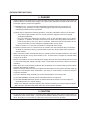
These 앬 SAFETY PRECAUTIONS 앬 classify the safety precautions into two categories: “DANGER” and
“CAUTION”.
PDANGER
Procedures which may lead to a dangerous condition and cause death
or serious injury if not carried out properly.
ECAUTION
Procedures which may lead to a dangerous condition and cause
superficial to medium injury, or physical damage only, if not carried out
properly.
Depending on circumstances, procedures indicated by E CAUTION may also be linked to serious
results.
In any case, it is important to follow the directions for usage.
Store this manual in a safe place so that you can take it out and read it whenever necessary. Always
forward it to the end user.
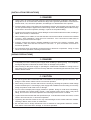
[DESIGN PRECAUTIONS]
P DANGER
• Install a safety circuit external to the PC that keeps the entire system safe even when there are
problems with the external power supply or the PC module. Otherwise, trouble could result from
erroneous output or erroneous operation.
(1) Outside the PC, construct mechanical damage preventing interlock circuits such as
emergency stop, protective circuits, positioning upper and lower limits switches and
interlocking forward /reverse operations.
(2) When the PC detects the following problems, it will stop calculation and turn off all output.
• The power supply module has over current protection equipment and over voltage
protection equipment.
• The PC CPUs self diagnostic functions, such as the watchdog timer error, detect
problems. In addition, all output will be turned on when there are problems that the PC
CPU cannot detect, such as in the I/O controller. Build a fail safe circuit exterior to the
PC that will make sure the equipment operates safely at such times.
Refer to Section 5.1 of this user’s manual for example fail safe circuits.
(3) Output could be left on or off when there is trouble in the output module relay or transistor.
So build an external monitoring circuit that will monitor any single output that could cause
serious trouble.
• When overcurrent which exceeds the rating or caused by short-circuited load flows in the output
module for a long time, it may cause smoke or fire. To prevent this, configure an external safety
circuit, such as fuse.
• Build a circuit that turns on the external power supply when the PC main module power is turned
on. If the external power supply is turned on first, it could result in erroneous output or erroneous
operation.
• When there are communication problems with the data link, the communication problem station
will enter the following condition.
Build an interlock circuit into the PC program that will make sure the system operates safely by
using the communication state information. Not doing so could result in erroneous output or
erroneous operation.
(1) For the data link data, the data prior to the communication error will be held.
(2) The MELSECNET (II,/B,/10) remote I/O station will turn all output off.
(3) The MELSECNET/MINI-S3 remote I/O station will hold the output or turn all output off
depending on the E.C. remote setting.
Refer to the data link manuals regarding the method for setting the communication problem
station and the operation state when there are communication problem.
E CAUTION
• Do not bunch the control wires or communication cables with the main circuit or power wires, or
install them close to each other. They should be installed 100mm(3.94inch) or more from each
other. Not doing so could result in noise that would cause erroneous operation.
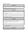
[INSTALLATION PRECAUTIONS]
P DANGER
• Use the PC in an environment that meets the general specifications contained in this manual.
Using this PC in an environment outside the range of the general specifications could result in
electric shock, fire, erroneous operation, and damage to or deterioration of the product.
• Install so that the pegs on the bottom of the module fit securely into the base unit peg holes, and
use the specified torque to tighten the module’s fixing screws. Not installing the module correctly
could result in erroneous operation, damage, or pieces of the product falling.
• Tightening the screws too far may cause damages to the screws and/or the module, resulting in
fallout, short circuits, or malfunction.
• When installing more cables, be sure that the base unit and the module connectors are installed
correctly. After installation, check them for looseness. Poor connections could result in
erroneous input and erroneous output.
• Correctly connect the memory cassette installation connector to the memory cassette. After
installation, make sure that the connection is not loose. A poor connection could result in
erroneous operation.
• Do not directly touch the module’s conductive parts or electronic components. Doing so could
cause erroneous operation or damage of the module.
[WIRING PRECAUTIONS]
P DANGER
• Completely turn off the external power supply when installing or placing wiring. Not completely
turning off all power could result in electric shock or damage to the product.
• When turning on the power supply or operating the module after installation or wiring work, be
sure that the unit’s terminal covers are correctly attached. Not attaching the terminal cover could
result in electric shock.
E CAUTION
• Be sure to ground the FG terminals and LG terminals to the protective ground conductor. Not
doing so could result in electric shock or erroneous operation.
• When wiring in the PC, be sure that it is done correctly by checking the product’s rated voltage
and the terminal layout. Connecting a power supply that is different from the rating or incorrectly
wiring the product could result in fire or damage.
• Do not connect multiple power supply modules in parallel. Doing so could cause overheating,
fire or damage to the power supply module. If the terminal screws are too tight, it may cause
falling, short circuit or erroneous operation due to damage of the screws or module.
• Tighten the terminal screws with the specified torque. If the terminal screws are loosen, it could
result in short circuits, fire, or erroneous operation.
• Tightening the terminal screws too far may cause damages to the screws and/or the module,
resulting in fallout, short circuits, or malfunction.
• Be sure there are no foreign substances such as sawdust or wiring debris inside the module.
Such debris could cause fires, damage, or erroneous operation.
[WIRING PRECAUTIONS]
E CAUTION
• External connections shall be crimped or pressure welded with the specified tools, or correctly
soldered. For information regarding the crimping and pressure welding tools, refer to the I/O
module’s user’s manual. Imperfect connections could result in short circuit, fires, or erroneous
operation.
[STARTUP AND MAINTENANCE PRECAUTIONS]
P DANGER
• Do not touch the terminals while power is on. Doing so could cause shock or erroneous
operation.
• Correctly connect the battery. Also, do not charge, disassemble, heat, place in fire, short circuit,
or solder the battery. Mishandling of battery can cause overheating or cracks which could result
in injury and fires.
• Switch all phases of the external power supply off when cleaning the module or tightening the
terminal screws. Not doing so could result in electric shock. If the screws are too tight, it may
cause falling, short circuit or erroneous operation due to damage of the screws or modules.
• Tightening the screws too far may cause damages to the screws and/or the module, resulting in
fallout, short circuits, or malfunction.
E CAUTION
• The online operations conducted for the CPU module being operated, connecting the peripheral
device (especially, when changing data or operation status), shall be conducted after the manual
has been carefully read and a sufficient check of safety has been conducted.
Operation mistakes could cause damage or trouble of the module.
• Do not disassemble or modify the modules. Doing so could cause trouble, erroneous operation,
injury, or fire.
• Switch all phases of the external power supply off before mounting or removing the module. If
you do not switch off the external power supply, it will cause failure or malfunction of the module.
[DISPOSAL PRECAUTIONS]
E CAUTION
• When disposing of this product, treat it as industrial waste.
REVISIONS
* The manual number is given on the bottom left of the back cover.
Print Date
*Manual Number
Revision
Apr.,1994
IB (NA) 66468-A
First edition
Dec.,1994
IB (NA) 66468-B
Correction
CONTENTS, Detailed manuals, Related manuals,
1.1, 1.2, 1.3, 1.4, 2.1, 2.2, 2.3, 3.1, 3.2
Addition
1.4, 1.5, 1.6
Jun.,1995
IB (NA) 66468-C
Overall revision
Oct.,1995
IB (NA) 66468-D
Correction
CONTENTS, 1, 2.2.1, 2.2.2, 2.2.3, 3.3, 3.5, 4.3.1,
4.3.2, 5.2, 7.2
Jan., 1996
IB (NA) 66468-E
Correction
CONTENTS, 4.1, 4.2, 5.1, 5.2, 6.1, 6.2, 6.3, 6.4, 6.5,
7.1, 7.2
Addition
3.2, 4.3.3
Apr., 1997
IB(NA) 66468-F
Addition of models
A1SHCPU, A2SHCPU(S1)
Addition
Grneral specifications, Low voltage instruction,
3.1, 5.3, 7.2, Appendix
Correction
Safety precautions, 4.2
Aug., 1997
IB(NA) 66468-G
Correction
CONTENTS, 3.4, 7.1, 7.3, Appendix 2, Appendix 5
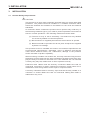
INTRODUCTION
Thank you for choosing the Mitsubishi MELSEC-A Series of General Purpose Programmable
Controllers. Please read this manual carefully so that the product is used to its optimum. A copy of
this manual should be forwarded to the end user.
This manual describes specifications and requirements related to safety, installations, wiring and
maintenance of the AnS series PC. For functional information, please refer to detail manuals of
each module.
Guidelines for the safety of the user and protection of the AnS series PC
This manual provides information for the installation and use of the AnS series PC. The manual
has been written to be used by trained and competent personnel. Please read the manual carefully
before installation and/or operations of the product. If the product is used in a manner not
specified by the manual, the protection provided by the product may be impaired.
Note: Definition of ‘trained and competent personnel’ is as follows:
a)
Any engineer who is responsible for the planning, design and construction of
automatic equipment using the product associated with this manual should be of a
competent nature, (trained and qualified to the local and national standards required
to fulfill that role). These engineers should be fully aware of all aspects of safety with
regards to automated equipment.
b)
Any commissioning or service engineer must be of a competent nature, trained and
qualified to the local and national standards required to fulfill that job. These
engineers should also be trained in the use and maintenance of the completed
product. This includes being completely familiar with all associated documentation
for the said product. All maintenance should be carried out in accordance with
established safety practices.
c)
All operators of the completed product should be trained to use that product in a safe
and co-ordinated manner in compliance to established safety practices. The
operators should also be familiar with all documentation which is connected with the
actual operation of the completed equipment.
Note: the term ‘completed equipment’ refers to a third party constructed device which
contains or uses the product associated with this manual.
Note’s on the symbols used in this manual
At various times through out this manual, certain symbols are used to highlight points of
information which are intended to ensure the users personal safety and protect the integrity of the
equipment. Whenever any of the following symbols are encountered, its associated note must be
read and understood. Each of the symbols used are listed with a brief description of its meaning.
Indicates that the identified danger could possibly cause serious physical
DANGER
injury and/or death.
P
ECAUTION
Indicates that the identified danger could possibly cause physical injury or
property damage.
Notification of CE marking
The following products have shown compliance through direct testing (to the
identified standards) and design analysis (forming a technical construction file)
to the European Directive for Electromagnetic Compatibility (89/336/EEC)
Products:
Type: Programmable Logic Controller
(Open Type equipment, Installation category II)
Model: AnS-Series
(Applicable units listed below)
Harmonised European Standards
IEC Standards
Reference No.
EN50081-2
prEN50082-2
EN50082-2
Reference No.
IEC801-2
IEC801-3
IEC801-4
Date of lssue
1992
1992
1995
Date of lssue
1984
1984
1988
AnS-Series Programmable Logic Controllers
Range of products:
A1S32B
A1S33B
A1S35B
A1S38B
A1S52B
A1S52B-S1
A1S55B
A1S55B-S1
A1S58B
A1S58B-S1
A1S61P
A1S61PEU
A1S61PN
A1S62DA
A1S62DA
A1S62P
A1S62PEU
A1S62PN
A1S62RD3
A1S62RD4
A1S63ADA
A1S63P
A1S64AD
A1S65B
A1S65B-S1
A1S68AD
A1S68B
A1S68B-S1
A1S68DAI
A1S68DAV
A1S68TD
A1SCPU
A1SCPU-S1
A1SHCPU
A1SD51S
A1SD61
A1SD70
A1SD71-S2
A1SD71-S7
A1SD75-P1
A1SD75-P2
A1SD75-P3
A1SG62
A1SH42
A1SH42
A1SI61
A1SJ51T64
A1SJ71AP21
A1SJ71AP21-S3
A1SJ71AR21
A1SJ71AT21B
A1SJ71E71-B2
A1SJ71E71-B5
A1SJ71LP21
A1SJ71PT32-S3
A1SJ71C24-PRF
A1SJ71C24-R2
A1SJ71C24-R4
A1SJ71UC24-PRF
A1SJ71UC24-R2
A1SJ71UC24-R4
A1SJ72T25B
A1SJCPU-S3
Models
A1SJHCPU
A1SP60
A1ST60
A1SX10EU
A1SX20EU
A1SX30
A1SX40
A1SX40-S1
A1SX40-S2
A1SX41
A1SX41-S2
A1SX42
A1SX42-S2
A1SX80
A1SX80-S1
A1SX80-S2
A1SX81
A1SX81-S2
A1SY10
A1SY10EU
A1SY14EU
A1SY18A
A1SY18AEU
A1SY22
A1SY28A
A1SY28EU
A1SY40
A1SY41
A1SY42
A1SY50
A1SY60E
A1SY68A
A1SY71
A1SY80
A1SY81
A1SY81EP
A2ASCPU
A2ASCPU-S1
A2ASCPU-S30
A2ASCPU-S60
A2SCPU
A2SCPU-S1
A2SHCPU
A2SHCPU-S1
A64DAIC
A64DAVC
A68ADC
AD61C
AJ55TB2-4R
AJ55TB2-8R
AJ55TB3-4D
AJ55TB3-8D
AJ55TB32-4DR
AJ55TB32-8DR
AX40Y50C
AX80Y14CEU
AX80Y80C
AX41C
AX81C
AY15CEU
AY51C
AY81C
The products listed above must be used as directed by the associated documentation in order to
provide full compliance. Please contact your local Mitsubishi Sales office or distributor for further
details.
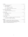
CONTENTS
1. ENVIRONMENTAL SPECIFICATIONS ...........................................................................................1 - 1
2. MODULE SPECIFICATIONS ............................................................................................. 2 - 1 to 2 - 8
2.1
Power Supply Modules ............................................................................................................2 - 1
2.2
Digital I/O Modules ...................................................................................................................2 - 3
2.2.1
Input modules .............................................................................................................2 - 3
2.2.2
Output modules ..........................................................................................................2 - 5
2.2.3
Input/output combined modules ...............................................................................2 - 7
3. INSTALLATION ................................................................................................................. 3 - 1 to 3 - 23
3.1
General Safety Requirements ................................................................................................3 - 1
3.2
Requirements for Compliance to EMC Directive (89/336/EEC) ........................................3 - 2
3.2.1
EMC standards ............................................................................................................3 - 2
3.2.2
Installation instructions for EMC ...............................................................................3 - 4
3.2.2.1
Controll cabinet ..........................................................................................3 - 4
3.2.2.2
Connection of power and earth wires...........................................3 - 4
3.2.2.3
Cables .........................................................................................................3 - 5
3.2.2.4
Shield earthing ...........................................................................................3 - 6
3.2.2.5
MELSECNET/II module.............................................................................3 - 6
3.2.2.6
Ethernet module .........................................................................................3 - 7
3.2.2.7
I/O and other communication cables .....................................................3 - 7
3.2.2.8
Power supply module ................................................................................3 - 7
3.2.2.9
Ferrite core .................................................................................................3 - 8
3.2.2.10 Noise filter (power supply line filter) .......................................................3 - 8
3.3
Requirment to Conform to the low Voltage Instruction .......................................................3 - 9
3.3.1
Standard applied for MELSEC-AnS..........................................................................3 - 9
3.3.2
Precautions When using the MELSEC-AnS series PC......................................... 3 -10
3.3.3
Power supply .............................................................................................................. 3 -10
3.3.4
Control box .................................................................................................................. 3 -11
3.3.5
Module installation ..................................................................................................... 3 -11
3.3.6
Grounding .................................................................................................................... 3 -12
3.3.7
External wiring ............................................................................................................ 3 -12
3.4
Module Handling ..................................................................................................................... 3 -13
3.5
Base Mounting ......................................................................................................................... 3 -14
3.6
Constructions to Reduce EMI Noise ..................................................................................... 3 -16
3.7
Precautions When Unfailure Power System (CPS) is Connected.................................... 3 -17
3.8
Part Indentification of the CPU .............................................................................................. 3 -18
3.9
RS232C Interface (A1SCPUC24-R2 only) ........................................................................... 3 -21
3.10 Self-Loopback Test (A1SCPUC24-R2 only) ........................................................................3 -23
–i–
4. WIRING ............................................................................................................................... 4 - 1 to 4 - 17
4.1
General Safety Requirements ................................................................................................4 - 1
4.2
Power Supply Modules ............................................................................................................4 - 2
4.3
Digital I/O Modules ...................................................................................................................4 - 5
4.3.1
Input module connections ..........................................................................................4 - 6
4.3.2
Output module connections ...................................................................................... 4 -10
4.3.3
Input/output composite module connections ...........................................................4 -16
5. FAIL-SAFE CONSTRUCTIONS ........................................................................................ 5 - 1 to 5 -3
5.1
General Safety Requirements ................................................................................................5 - 1
5.2
Fail-Safe Circuitry Against to Failure of the PC...................................................................5 - 1
6. MAINTENANCE ................................................................................................................... 6 - 1 to 6 - 4
6.1
General Safety Requirement ..................................................................................................6 - 1
6.2
Daily Inspection ........................................................................................................................6 - 2
6.3
Periodic Inspection ...................................................................................................................6 - 3
6.4
Battery Replacement................................................................................................................6 - 4
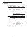
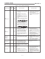
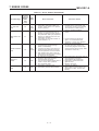
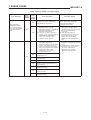
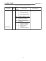
7. ERROR CODES ................................................................................................................. 7 - 1 to 7 - 14
7.1
Error Code List for A1SCPU(S1), A1SCPUC24-R2 and A2SCPU(S1) ............................7 - 1
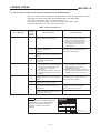
7.2
Error Code List for A2ASCPU(S1/S30/S60) .........................................................................7 - 5
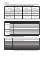
7.3
Error Code List for A1SHCPU, A2SHCPU(S1) ................................................................... 7 -14
APPENDIX ................................................................................................................................. A - 1 to A
Appendix 1 Dissimilarities between A1SHCPU and A1SCPU(S1)............................................. A
Appendix 2 Dissimilarities between A2SHCPU(S1) and A2SCPU(S1) ..................................... A
Appendix 3 Diffrernces between A2SCPU-S30/S60 and A2ASCPU(S1).................................. A
Appendix 4 CE Marking Compatible Module for Compact PC ................................................... A
Appendix 5 CC-Link Dedicated Instructions List .......................................................................... A
– ii –
-
2
1
1
2
2
2
This manual describes cautions on handling, connection to I/O modules, and
error codes of A1SCPU(S1), A2SCPU(S1), A2ASCPU(S1/S30/S60), and
A1SHCPU, A1SHCPU(S1), A1SCPUC24-R2 (hereafter called “the CPU”).
Refer to the following manuals when necessary.
Detailed manuals
• A1SCPU/A1SCPUC24-R2/A2SCPU User’s Manual (IB-66320)
This manual describes the specifications and functions of A1S, A1SC24-R2
and A2SCPU(S1), and specifications etc. of the memory cassettes, the
power supply module and extension base unit.
• A2ASCPU(S1) User’s Manual (IB-66455)
This manual describes the specifications and functions of A2ASCPU(S1)
and the specifications of the memory cassettes, the power supply modules
and extension base units that can be used with it.
• A1SJHCPU/A1SHCPU/A2SHCPU(S1) User’s Manual (IB-66779)
This manual describes the specifications and functions of A1SJHCPU,
A1SH, and A2SHCPU(S1) and the specifications of the memory cassettes,
the power supply modules and extension base units that can be used with
it.
Related manuals
• ACPU Programming Manual (Fundamentals) (IB-66249)
This manual describes programming methods required to create programs,
device names, parameters, types of program, configuration of the memory
area, etc.
• ACPU Programming Manual (Common Instructions) (IB-66250)
This manual describes how to use the sequence instructions, basic instructions, application instructions and micro-computer programs.
• AnACPU/AnUCPU Programming Manual (Dedicated Instructions)
(IB-66251)
This manual describes the extended instructions for the A2ASCPU(S1).
• AnACPU/AnUCPU Programming Manual (AD57 control instructions)
(IB-66257)
This manual describes the dedicated instructions used to control AD57(S1)/
AD58 CRT/LCD control modules with an A2ASCPU(S1).
• AnACPU/AnUCPU Programming Manual (PID control instructions)
(IB-66258)
This manual describes the dedicated instructions used to execute PID
control with an A2ASCPU(S1).
• AnS Module type I/O User’s Manual (IB-66541)
This manual gives the specifications for AnS module type I/O modules.
• Computer Link Module User’s Manual (Comms. link func./ Print func.)
(SH-3511)
This manual describes communication between the A1SCPUC24-R2 and
external devices using the dedicated protocol, no protocol, and bidirectional
modes, and the settings, wiring, programming, troubleshooting, etc., for this
module.
• Computer Link Module Guidebook (SH-3510)
This manual gives the basic information required to execute data communication with external devices (computers, for example), in each mode of the
computer link function.
• MELSECNET, MELSECNET/B Data Link System Reference Manual
(IB-66350)
This manual describes the performance, functions and programming methods for the MELSECNET and MELSECNET/B data link systems.
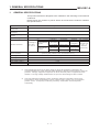
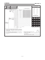
1. GENERAL SPECIFICATIONS
1.
MELSEC-A
GENERAL SPECIFICATIONS
This product has been designed to be installed in the following environmental
conditions.
Please place the product in places where environmental conditions satisfies
the specifications.
Item
Specifications
Ambient operating
temperature
0 to 55°C
Ambient storage
temperature
-20 to 75°C
Ambient operating
humidity
10 to 90% RH, Non-condensing
Ambient storage humidity
10 to 90% RH, Non-condensing
Frequency
Vibration resistance
Conforming to
JIS B 3501,
IEC 1131-2
Under intermittent
vibration
Under continuous
vibration
Acceleration
Amplitude
10 to 57Hz
—
0.075mm
(0.003inch)
57 to 150Hz
9.8m/s 2 {1G}
—
10 to 57Hz
—
0.035mm
(0.001inch)
57 to 150Hz
4.9m/s2 {0.5G}
—
No. of sweeps
10 times each
in X, Y, Z
directions
(for 80 min.)
Conforming to JIS B3501, IEC 1131-2
(147m/s 2 {15G}, 3 times in each of 3 directions X Y Z)
Shock resistance
Operating ambience
No corrosive gases
Operating elevation
2000m (6562 feet) max.
Installation location
Control panel
Over voltage category * 1
II max.
Pollution level * 2
2 max.
*1:
This indicates the section of the power supply to which the equipment is assumed to be
connected between the public electrical power distribution network and the machinery within the
premises. Category II applies to equipment for which electrical power is supplied from fixed
facilities. The surge voltage withstand level for up to the rated voltage of 300V is 2500V.
*2:
This index indicates the degree to which conductive material is generated in terms of the
environment in which the equipment is used. Pollution level 2 is when only non-conductive
pollution occurs. A temporary conductivity caused by condensation must be expected
occasionally.
1–1
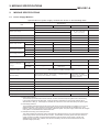
2. MODULE SPECIFICATIONS
MELSEC-A
2.
MODULE SPECIFICATIONS
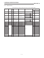
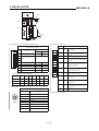
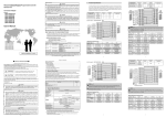
2.1
Power Supply Modules
Specifications of power supply modules are shown in the following table
Specifications
Item
A161P
A1S62P
Base loading slot
A1S63P
Power supply module loading slot
100 to 120 VAC+10%/-15%(85 to 132 VAC)
24 VDC +30%/-35%
(15.6 to 31.2VDC)
Rated input voltage
200 to 240 VAC+10%/-15%(170 to 264 VAC)
50/60 Hz ±3%
Rated input frequency
105 VA
41 Ω
20 A 8 ms or lower
81 A 1 ms or lower
Max. input apparent power
Inrush current
5 VDC
5A
3A
5A
24 VDC±10%
0.6 A
5 VDC
5.5 A or higher
3.3 A or higher
5.5 A or higher
24 VDC
0.66 A or higher
Rated output current
Overcurrent protection
5 VDC
5.5 to 6.5 V
Overvoltage protection
24 VDC
Efficiency
65% or higher
Allowable momentary power failure time *3
Dielectric withstand
voltage
20ms or lower
1ms or lower
Between primary
and 5 VDC
1500 VAC *1
1500 VAC *1
500 VAC
Between primary
and 24 VDC
1500 VAC *1
5M Ω or highter at insulation resistance tester
Insulation resistor
Noise voltage 1500Vp-p, Noise width 1 µs, Noise frequency
25 to 60Hz (noise simulator condition)
Noise durability
Power indication
Noise voltage 500Vp-p,
Noise width 1 µs, Noise
frequency 25 to 60Hz (noise
simulator condition)
Power LED indication (light at the time of output of 5VDC)
Terminal screw size
M3.5 × 7
Applicable wire size
0.75 to 2mm 2 (AWG18 to 14)
Applicable solderless terminal
RAV1.25 to 3.5, RAV2 to 3.5
Applicable tightenig torque
59 to 88 N⋅cm (6 to 9kg⋅cm)
130 × 55 × 93.6 (5.12 × 2.17 × 3.69)
External dimension mm (inch)
Weight kg (lb)
0.53 (1.17)
0.55 (1.21)
0.5 (1.1)
*1: Overcurrent protection
The overcurrent protection device shuts off the 5V, 24 VDC circuit and stops the system if the current flowing
in the circuit exceeds the specified value. When this device is activated, the power supply module LED is
switched OFF or dimly lit. If this happens, eliminate the cause of the overcurrent and start up the system again.
*2: Overvoltage protection
The overvoltage protection device shuts off the 5 VDC circuit and stops the system if a voltage of 5.5 to 6.5 V is
applied to the circuit. When this device is activated, the power supply module LED is switched OFF. If this
happens, switch the input power OFF, then ON to restart the system. The power supply module must be changed
if the system is not booted and the LED remains OFF.
*3: Allowable momentary power interruption time
This value indicates the momentary power interruption time allowed for the PC CPU and varies according to the
power supply module used with the PC CPU module. The allowable momentary power interruption time for a
system in which an A1S63P is used is defined as starting when the primary power supply of the 24 VDC
stabilized power supply of the A1S63P is turned OFF and lasting until the 24 VDC becomes less than the
specified voltage (15.6 VDC).
2–1
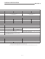
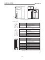
2. MODULE SPECIFICATIONS
MELSEC-A
A1S61PEU
A1S62PEU
A1S61PN
200 to 240 VAC (10%/-15%)
(170 to 264VAC)
A1S62PN
100 to 240 VAC(10%/-15%)
(85 to 264VAC)
50/60 Hz ±5%
105VA
40 A 8ms or lower
20A 8ms or lower
5A
3A
5A
3A
0.6A
0.6A
5.5 A or higher
3.3 A or higher
5.5 A or higher
3.3 A or higher
0.66A or higher
0.66 A or higher
20ms or higher
1780 VAC
1780 VAC
1780 VAC
AC across input/LG and output/FG 2830VAC rms/3cycle (2000m)
5M Ω or highter at insulation resistance tester
AC across input/LG and output/FG5M Ω or highter, mesured with a
500VDC insulation resistance tester
(1) Noise voltage 1500Vp-p, Noise width 1 µs,
Noise frequency 25 to 60Hz (noise simulator condition)
(2) Noise voltage IEC801-4, 2kV
RAV1.25 to 3.5, RAV2 to 3.5
RAV1.25 to 4, RAV2 to 4
59 to 88 N⋅cm (6 to 9 kg⋅cm)
83 to 113 N⋅cm (8.5 to 11.5 kg⋅cm)
130 × 55 × 93.6 (5.12 × 2.17 × 3.69)
130 × 54.5 × 93.6 (5.12 × 2.15 × 3.69)
0.53 (1.17)
0.55 (1.21)
0.60(1.32)
*4: A1S61PEU and A1S62PEU comply with EN61010-1 and safety aspects of IEC1131-2 to meet the Low Voltage
Directive which will be mandatory from the 1st of January 1997.
*5: Do not apply over 400 Voltage between AC and LG as the Varistor is installed between the AC and LG.
2–2
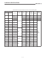
2. MODULE SPECIFICATIONS
MELSEC-A
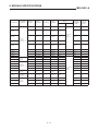
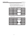
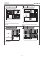
2.2
Digital I/O Modules
2.2.1
Input modules
Specifications of input modules are shown in the following table.
Operating Voltage
Model
Type
A1SX10
A1SX10EU
No. of
Points
16
AC input
Rated Input
Voltage
100 to 120 VAC,
50/60 Hz
16
A1SX20
16
A1SX20EU
16
200 to 240 VAC,
50/60 Hz
Input
Current
Dielectric
Withstand
Voltage
6 mA
1500 VAC
7 mA
1780 VAC
9 mA
1500 VAC
11 mA
2830 VAC
ON Voltage
80 VAC or
higher
OFF Voltage
30 VAC or
lower
Maximum
Simultaneous
Input Points
(Percentage
Simultaneously
ON)
100% (110 VAC)
60% (132 VAC)
100%
80 VAC or
higher
30 VAC or
lower
60% (220 VAC)
16
12/24 VAC,
50/60 Hz
12/24 VDC
4.2/8.6 mA
7 VAC/VDC or
higher
2.7 VAC/VDC
or lower
75% (26.4 VAC)
A1SX40
16
12/24 VDC
3/7 mA
8 VDC or
higher
4 VDC or lower
100%
(26.4 VDC)
A1SX40-S1
16
24 VDC
7 mA
14 VDC or
higher
6.5 VDC or
lower
100%
(26.4 VDC)
A1SX40-S2
16
24 VDC
7 mA
14 VDC or
higher
6.5 VDC or
lower
100%
(26.4 VDC)
32
12/24 VDC
3/7 mA
8 VDC or
higher
4 VDC or lower 60% (26.4 VDC)
A1SX41-S2
32
24 VDC
7 mA
14 VDC or
higher
6.5 VDC or
lower
A1SX42
64
12/24 VDC
2/5 mA
8 VDC or
higher
4 VDC or lower 50% (24 VDC)
A1SX42-S2
64
24 VDC
5 mA
17.5 VDC or
higher
7 VDC or lower 50% (24 VDC)
A1SX71
32
5/12 VDC
1.2/3.3 mA
3.5 VDC or
higher
1 VDC or lower 100%
A1SX80
16
12/24 VDC
3/7 mA
8 VDC or
higher
4 VDC or lower
100%
(26.4 VDC)
16
24 VDC
7 mA
17 VDC or
higher
5 VDC or lower
100%
(26.4 VDC)
A1DX80-S2
16
24 VDC
7 mA
13 VDC or
higher
6 VDC or lower
100%
(26.4 VDC)
A1SX81
32
12/24 VDC
3/7 mA
8 VDC or
higher
4 VDC or lower 60% (26.4 VDC)
A1SX81-S2
32
24 VDC
7 mA
13 VDC or
higher
6 VDC or lower 60% (26.4 VDC)
16/32/
48/64
12/24 VDC
4/9 mA
8 VDC or
higher
4 VDC or lower
A1SX30
A1SX41
A1SX80-S1
A1S42X
AC/DC input
DC input
(sink type)
DC input
(sink/source)
DC input
(dynamic)
2–3
500 VAC
60% (26.4 VDC)
100%
(26.4 VDC)
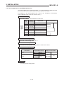
2. MODULE SPECIFICATIONS
MELSEC-A
Specifications of input modules are shown in the following table.
Max. Response Time
Field Wiring
OFF to ON
20 ms
30 ms
ON to OFF
Applicable Wire
Size
Points/
Common
Noise
Immunity
Internal
Current
Consumption
(5 VDC)
No. of
Occupied
Points
Terminal
16
1000 VAC
0.05 A
16
Terminal
16
1000 VAC
0.05 A
16
Terminal
16
1500 VAC
0.05 A
16
Terminal
16
1000 VAC
0.05 A
16
1500 VAC
0.05 A
16
Power
Supply
Requirement
35 ms
55 ms
25 ms
20 ms
20 ms
20 ms
Terminal
0.75 to 1.25 mm 2
AWG 15 to 19
16
10 ms
10 ms
Terminal
16
500 VAC
0.05 A
16
0.1 ms
0.2 ms
Terminal
16
500 VAC
0.05 A
16
10 ms
10 ms
Terminal
16
500 VAC
0.05 A
16
10 ms
10 ms
40-pin connector
32
500 VAC
0.08 A
32
10 ms
10 ms
40-pin connector
32
500 VAC
0.08 A
32
32
500 VAC
0.09 A
64
0.3 mm 2
AWG22
10 ms
10 ms
40-pin connector
10 ms
10 ms
40-pin connector
32
500 VAC
0.09 A
64
1.5 ms
3 ms
40-pin connector
32
500 VAC
0.075 A
32
10 ms
10 ms
Terminal
16
1000 VAC
0.05 A
16
16
1000 VAC
0.05 A
16
0.75 to 1.25 mm
AWG15 to 19
2
0.4 ms
0.5 ms
Terminal
10 ms
10 ms
Terminal
16
1000 VAC
0.05 A
16
10 ms
10 ms
37-pin connector
32
1000 VAC
0.08 A
32
10 ms
10 ms
37-pin connector
32
1000 VAC
0.08 A
32
0.4 ms
0.4 ms
24-pin connector
500 VAC
0.08 A
16/32/48/64
0.3 mm 2
AWG22
2–4
SELV
power
supply is
required
2. MODULE SPECIFICATIONS
MELSEC-A
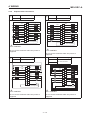
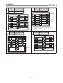
2.2.2
Output modules
Specifications of output modules are shown in the following table.
Model
Type
No.
of
Rated Load Voltage
Points
Max. Output Response
Time
Max. Load Current
Dielectric Withstand Voltage
OFF to
ON
A1SY10
Relay output
16
240 VAC, 50/60 Hz
24 VDC
2 A/pt, 8 A/com
1500 VAC
Relay output
(for 24 VDC)
16
120 VAC, 24 VDC
2 A/pt, 8 A/com
AC terminal-Relay
coil, 5 VAC
1780 VAC
A1SY10EU
Relay coil, 5 VAC
500 VAC
AC terminal-Relay
coil, 5 VAC
2830 VAC
Relay coil, 5 VAC
500 VAC
A1SY14EU
Relay output
12
240 VAC, 24 VDC
2 A/pt, 8 A/com
A1SY18A
Relay output
8
240 VAC, 50/60 Hz
24 VDC
2 A/pt, 8 A/module
1500 VAC
Relay output
8
240 VAC, 24 VDC
2 A/pt
AC terminal-Relay
coil, 5 VAC
2830 VAC
A1SY18AEU
Relay coil, 5 VAC
500 VAC
A1SY22
Triac output
A1SY28A
Triac output
A1SY28EU
Triac output
A1SY40
A1SY41
12 ms
10 ms
12 ms
10 ms
12 ms
10 ms
12 ms
10 ms
12 ms
1 ms
0.5 cycle + 1 ms
0.6 A/pt, 2.4 A/com
8
240 VAC, 50/60 Hz
1 A/pt, 4 A/module
1500 VAC
1 ms
0.5 cycle + 1 ms
8
100 - 240 VAC
0.6 A/pt, 1.9 A/com
2830 VAC
1 ms
0.5 cycle + 1 ms
16
12/24 VDC
0.1 A/pt, 0.8 A/com
2 ms
2 ms
32
12/24 VDC
0.1 A/pt, 2 A/com
2 ms
2 ms
A1SY42
64
12/24 VDC
0.1 A/pt, 1.6 A/com
2 ms
2 ms
A1SY50
16
12/24 VDC
0.5 A/pt, 2 A/com
2 ms
2 ms
16
24 VDC
2 A/pt, 4 A/com
2 ms
2 ms
A1SY60E
A1SY68A
Transistor
output
1500 VAC
10 ms
240 VAC, 50/60 Hz
A1SY60
16
ON to OFF
500 VAC
16
5/12/24 VDC
2 A/pt, 4 A/com
3 ms
10 ms
8
5/12/24 VDC
2 A/pt
3 ms
10 ms
A1SY71
32
5/12 VDC
16 mA/pt, 256 mA/com
1 ms
1 ms
A1SY80
16
12/24 VDC
0.8 A/pt, 3.2 A/com
2 ms
2 ms
A1SY81
32
12/24 VDC
0.1 A/pt, 2 A/com
2 ms
2 ms
0.5ms
1.5ms
2 ms
2 ms
A1SY81EP
32
12/24 VDC
0.1 A/pt, 2 A/com
0.05 A/pt, 1.6 A/com
A1S42Y
64
12/24 VDC
0.1 A/pt
2–5
2. MODULE SPECIFICATIONS
MELSEC-A
Field Wiring
Applicable
Wire Size
Points/
Common
Surge
Suppression
External Power
Supply
Noise
Durability
Fuse Rating
Current
Internal
Current
Consumption
(5 VDC)
Requirement
No of
Occupied
Points
Terminal
8
None
None
1000 VAC
0.09 A
0.12 A
16
Terminal
8
None
None
1000 VAC
0.09 A
0.12 A
16
Terminal
4
None
None
1000 VAC
0.1 A
0.12 A
16
1
None
None
1000 VAC
0.075 A
0.24 A
16
None
None
1000 VAC
0.75 A
0.24 A
16
0.02 A
0.27 A
16
Terminal
0.75 to
1.25 mm 2
AWG15 to 19
Terminal
SELV power
supply
required
Terminal
8
CR
5A
1500 VAC
Terminal
1
CR
None
1500 VAC
0.13 A
16
Terminal
4
CR
None
1000 VAC
0.27 A
16
8
Zener diode
1.6 A
500 VAC
0.08 A
0.27 A
16
32
Zener diode
3.2 A
500 VAC
0.08 A
0.5 A
32
32
Zener diode
3.2 A
500 VAC
0.08 A
0.93 A
64
Terminal
40-pin connector
40-pin connector
2
0.3 mm
AWG22
Terminal
Terminal
Terminal
0.75 to
1.25 mm 2
AWG15 to 19
Terminal
8
Zener diode
3.2 A
500 VAC
0.06 A
0.12 A
16
8
Zener diode
5A
500 VAC
0.015 A
0.12 A
16
8
Zener diode
7A
500 VAC
0.01 A
1
Zener diode
None
500 VAC
32
None
1.6 A
500 VAC
Zener diode
5A
32
Zener diode
32
Clamping
diode
None
40-pin connector.
0.3mm 2
AWG22
Terminal
0.75 to
8
1.25 mm 2
AWG15 to 19
37-pin connector
37-pin connector
24-pin connector
0.3 mm 2
AWG22
0.2 A
16
0.11 A
16
0.15 A
0.4 A
32
1000 VAC
0.02 A
0.12 A
16
3.2 A
1000 VAC
0.08 A
0.5 A
32
None
1000VAC
0.08A
0.5A
32
1.6 A
500 VAC
0.08 A
0.1 A
16/32/48/64
2–6
SELV power
supply
required
2. MODULE SPECIFICATIONS
MELSEC-A
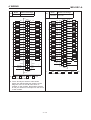
2.2.3
Input/output combined modules
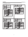
Specifications of input/output combined modules are shown in the following
table.
(1)
Input specifications
Operating Voltagee
Model
A1SH42
A1SX48Y18
No. of
Points
Type
DC input
(sink type)
A1SX48Y58
Type
Input
Current
32
12/24 VDC
2/5 mA
8
24 VDC
7 mA
8
24 VDC
7 mA
(2)
Model
Rated Input
Voltage
Insulation
Withstand
Voltage
500 VAC
ON Voltage
OFF Voltage
Maximum
Simultaneous
Input Points
(Percentage
Simultaneously
ON)
8 VDC or
higher
4 VDC or
lower
60%
(24 VDC)
14 VDC or
higher
6.5 VDC or
lower
100%
(26.4 VDC)
14 VDC or
higher
6.5 VDC or
lower
100%
(26.4 VDC)
Output specifications
No. of Points
Rated Load
Voltage
Max. Load
Current
A1SH42
Transistor
output
32
12/24 VDC
0.1 A/pt,
0.8 A/com
A1SX48Y18
Relay output
8
2 A/pt,
240 VAC,
50/60 Hz 24 VDC 8 A/com
A1SX48Y58
Transistor
output
8
12/24 VDC
0.5 A/pt,
2 A/com
2–7
Dielectric
Withstand
Voltage
Max. Output Response Time
OFF to ON
ON to OFF
500 VAC
0.4 ms
0.4 ms
1500 VAC
10 ms
12 ms
500 VAC
2 ms
2 ms
2. MODULE SPECIFICATIONS
MELSEC-A
Max. Response Time
Applicable
Wire Size
Field Wiring
OFF to ON
ON to OFF
10 ms
10 ms
40-pin
connector
0.3 mm 2
AWG22
10 ms
10 ms
Terminal
10 ms
10 ms
Terminal
0.75 to 1.25
mm 2
AWG15 to 19
Field Wiring
Applicable
Wire Size
40-pin connector
0.3 mm 2
AWG22
Terminal
0.75 to 1.25
mm 2
AWG 15 to 19
Terminal
Points/
Common
Points/
Common
Noise
Durability
Internal
Current
Consumption
(5 VDC)
No. of
Occupied
Points
32
500 VAC
0.05 A
32
8
500 VAC
0.05 A
16
8
500 VAC
0.05 A
16
Surge
Suppression
Fuse Rating
Noise
Durability
SELV power
supply
required
External Power Supply
Current
32
None
None
500 VAC
0.08 A
8
Zener diode
3.2 A
1000 VAC
0.045 A
8
None
None
500 VAC
0.06 A
2–8
Power
Supply
Requirement
Requirement
SELV power
supply required
MEMO
3. INSTALLATION
MELSEC-A
3.
INSTALLATION
3.1
General Safety Requirements
E CAUTION
This product is an open type equipment and itself does not comply with IP2X
protection. The product must be installed in a suitable enclosure which
should be selected and installed in accordance to the local and national
standards.
An enclosure which contains the product can be opened only under any of
the following conditions (a) to (c) in order to protect operators from electrical
shock in normal operations. The following measures must be taken:
(a) The use of a key or tool is necessary. This method is only allowed
for access by skilled or instructed persons.
(b) Disconnection of supplied power before the enclosure is opened.
(c) Barriers should be provided for all live parts except those supplied
by Extra-Low Voltage.
This products must be installed and used in environment specified as the
environmental specifications. Otherwise, using in different environment
could cause electrical shock, fire, malfunction, damage of the products
and/or decrease of product capability.
When mounting a module onto a base unit, securely insert the fixing hook on
the bottom of the module into the hole provided on the base unit at first, then
plug the body of module on the base unit. If the modules are not mounted
correctly they may fall, malfunction or fail to operate correctly.
Extension base cables must be securely connected. Make sure that no
unsecured connection is made. Unsecured connection could cause PC to
read and/or write wrong status from/to input or output modules.
A memory cassette module or memory chips must be securely loaded on a
connector or socket. Make sure that no unsecured loading was made or
malfunction may occur.
3–1
3. INSTALLATION
3.2
MELSEC-A
Requirements for Compliance to EMC Directive (89/336/EEC)
The EMC Directive (89/336/EEC) will become mandatory within Europe from
January 1st 1996. The EMC directive in essence defines the amount of
electromagnetic output a product is allowed to produce and how susceptible
that product is to electromagnetic interference. Any manufacturer or importer
of electrical/electronic apparatus must before releasing or selling products
within Europe after that date have either a CE mark attached to their goods.
Testing to comply with the directive is done by use of agreed European
standards which define limits for radiated and mains conducted electro-magnetic emissions from equipment, levels of immunity to radiated emissions,
ability for equipment to cope with transient voltage surges and electro-static
discharges.
When installed in the specified manner this unit will be compliant with the
relevant standards EN50081-2 and prEN50082-2 as applicable in the EMC
directive. Failure to comply with these instructions could lead to impaired
EMC performance of the equipment and as such Mitsubishi Electric Corporation can accept no liability for such actions.
3.2.1
EMC standards
When the PC is installed following the directions given in this manual its EMC
performance is compliant to the following standards and levels as required
by the EMC directive.
Specifications
Test Item
Test Description
Standard Values
EN55011
Radiated noise
Measure the electric wave
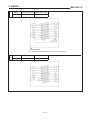
released by the product.
30M-230MHz
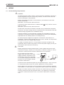
QP : 30dBµV/m (30m measurement) *1
EN55011
Conduction noise
Measure the noise released
by the product to the power
line.
150k-500kHz QP: 79dB, Mean : 66dB *1
IEC801-2
Static electricity immunity *2
Immunity test by applying
static electricity to the
module enclosure.
4kV contact discharge
IEC801-3
Radiated electromagnetic field *2
Immunity test by radiating
an electric field to the
product.
10V/m, 27-500MHz
IEC801-4
First transient burst noise
Immunity test by applying
burst noise to the power
line and signal cable.
2kV
EN61000-4-2
Static electricity immunity *2
Immunity test by applying
static electricity to the
module enclosure.
EN61000-4-4
First transient burst noise
Immunity test by applying
burst noise to the power
line and signal cable.
2kV
ENV50140
Radiated electromagnetic field
AM modulation*2
Immunity test by radiating
an electric field to the
product.
10V/m, 80-1000MHz, 80% AM modulation@1kHz
ENV50204
Radiated electromagnetic field
Pulse modulation*2
Immunity test by radiating
an electric field to the
product.
10V/m, 900MHz, 200Hz pulse modulation, 50%
duty
ENV50141
Conduction noise
Immunity test by inducting
electromagnetic field to the
power line signal cable.
10Vrms, 0.15-80MHz, 80% modulation@1kHz
230M-1000MHz QP : 37dBµV/m (30m measurement)
EN50081-2: 1995
prEN50082-2: 1991
EN50082-2: 1995
3–2
500k-30MHz QP : 73dB, Mean: 60dB
8kV air discharge
4kV contact discharge
8kV air discharge
3. INSTALLATION
MELSEC-A
(*1) QP: Quasi-peak value, Mean: Average value
(*2) The PC is an open type device(device installed to another device) and
must be installed in a conductive control box.
The tests for the corresponding items were perfomed while the PC was
installed to inside the control box.
3–3
3. INSTALLATION
3.2.2
3.2.2.1
MELSEC-A
Installation instructions for EMC
Control cabinet
When constructing a control cabinet where the PC system will be installed,
the following instructions must be followed.
3.2.2.2
(1)
Use a conductive control cabinet.
(2)
When attaching the control cabinet’s top plate or base plate, mask
painting and weld so that good surface contact can be made between
the cabinet and plate.
(3)
To ensure good electrical contact with the control cabinet, mask the
paint on the installation bolts of the inner plate in the control cabinet so
that contact between surfaces can be ensured over the widest possible
area.
(4)
Earth the control cabinet with a thick wire so that a low impedance
connection to ground can be ensured even at high frequencies. (22 mm 2
wire or thicker is recommended.)
(5)
Holes made in the control cabinet must be 10 cm diameter or less. If the
holes are 10 cm or larger, radio frequency noise may be emitted.
(6)
Connect the door of cabinet to the main body with flat braided wires at
as many points as possible so that a low impedance can be ensured
even at high frequencies.
Connection of power and earth wires
Earthing and power supply wires for the PC system must be connected as
described below.
(1)
Provide an earthing point near the power supply module. Earth the
power supply’s LG and FG terminals (LG: Line Ground, FG: Frame
Ground) with the thickest and shortest wire possible. (The wire length
must be 30 cm or shorter.) The LG and FG terminals function is to pass
the noise generated in the PC system to the ground, so an impedance
that is as low as possible must be ensured. As the wires are used to
relieve the noise, the wire itself carries a large noise content and thus
short wiring means that the wire is prevented from acting as an antenna.
Note) A long conductor will become a highly efficient antenna at high frequency.
(2)
The earth wire lead from the earthing point must be twisted with the
power supply wires. By twisting with the earthing wire, noise flowing
from the power supply wires can be relieved to the earthing. However,
if a filter is installed on the power supply wires, the wires and the
earthing wire may not need to be twisted.
(3)
Except for A1S61PEU and A1S62PEU, short between FG and LG
terminals by a short jumper wire.
3–4
3. INSTALLATION
3.2.2.3
MELSEC-A
Cables
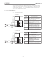
The cables led from the control cabinet contain a high frequency noise
element and outside the control panel these cables act as antenna and
radiate noise. The cables connected to input/output modules or special
modules which leave the control panel must always be shielded cables.
Mounting of a ferrite core on the cables is not required (excluding some
models) but if a ferrite core is mounted, the noise radiated through the cable
can be suppressed further.
Use of a shielded cable is also effective for increasing the noise immunity
level. The PC system’s input/output and special function module provide a
noise immunity level of equivalent to that stated in IEC801-4: 2 kV when a
shielded cable is used. If a shielded cable is not used or if the shield earthing
treatment is not suitable even when used (refer to section 3.2.2.4), the noise
immunity level is less than 2 kV
Note) prEN50082-2 specifies the noise resistance level based on the signal
wire application
Signals involved in process control:
2 kV
Signals not involved in process control: 1 kV
The meaning of “involved in process control” is not defined in prEN50082-2.
However, when the purposes of the EMC Directive are considered, the
signals that could cause personal injury or risks in the facility if a malfunction
occurs should be defined as “signals involved in process control”. Thus, it is
assumed that a high noise immunity level is required.
3–5
3. INSTALLATION
3.2.2.4
MELSEC-A
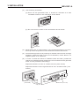
Shield earthing
When a shield of shield cable is earthed to the cabinet body, please ensure
that the shield contact with the body is over a large surface area. If the
cabinet body is painted it will be necessary to remove paint from the contact
area. All fastenings must be metallic and the shield and earthing contact must
be made over the largest available surface area. If the contact surfaces are
too uneven for optimal contact to be made either use washers to correct for
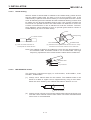
surface inconsistencies or use an abrasive to level the surfaces. The following diagrams show examples of how to provide good surface contact of
shield earthing by use of a cable clamp.
Screw
Clamp fitting
Shield section
Paint mask
(a) Peal the cable insulation off
and expose the shield section.
Shielded cable
(b) Sandwich the exposed shield section with the clamp
and earth to the control cabinet over a wide area.
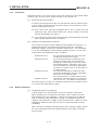
Note) The method of earthing by soldering a wire onto the shield section of
the shielded cable as shown below is not recommended. The high
frequency impedance will increase and the shield will be ineffective.
Shielded cable
Wire
Crimp terminal
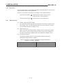
3.2.2.5
MELSECNET/II module
The following requirements apply to A1SJ71AR21, A1SJ71BR11, AnNCPUR21, AnACPUR21.
(1)
Always use a triaxial cable for the module. The radiated noise in the
band of 30 MHz or higher can be suppressed by using a triax cable.
Earth the outer shield by the method described in Section 3.2.2.4.
Earth this section
(2)
Always mount a ferrite core onto the triaxial cable. Mount the ferrite core
near the control cabinet outlet of each cable. Use of the TDK ZCAT3035
ferrite core is recommended.
3–6
3. INSTALLATION
3.2.2.6
MELSEC-A
Ethernet module
(1)
Always earth the AUI cable connected to the A1SJ71E71-B5. The AUI
is a shielded cable so remove the outer insulation and connect to earth
the exposed shield section using as wide a surface area as possible in
the manner shown below.
AUI cable
Shield
3.2.2.7
(2)
Always use a triaxial cable for the coaxial cable connected to the
A1SJ71E71-B2. The earthing precautions are the same as Section
3.2.2.5.
(3)
For A1SJ71E71-B2/B5, always mount a ferrite core in addition to items
(1) and (2) above. Use of the TDK ZCAT3035 ferrite core is recommended.
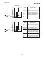
I/O and other communication cables
Always earth the shield section of the I/O signal cables and other communication cables (RS-232-C, RS-422, etc.) in the same manner as described in
Section 3.2.2.4 if the cables go outside of the control cabinet.
3.2.2.8
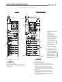
Power supply module
The precautions required for each power supply module are described below.
Always observe the items noted as precautions.
Model
Precautions
A1S61P
A1S62P
A1S63P (*1)
Always mount one of the filters listed in section 3.2.2.10 to the incoming
power supply lines.
A1S61PEU
A1S62PEU
A1S61PN
A1S62PN
None
(*1) If a sufficient filter circuitry is built into a 24 VDC external power supply
unit, the noise generated by A1S63P will be absorbed by that filter
circuit, so a line filter may not be required.
3–7
3. INSTALLATION
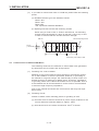
3.2.2.9
MELSEC-A
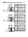
Ferrite core
A ferrite core is effective for reducing noise in the band of 30 MHz to 100
MHz. Mounting of a ferrite core is not necessary except for some particular
models described in Section 3.2.2.5 and 3.2.2.6. However if further attenuation of noise is necessary, mounting of a ferrite core on cables which radiate
noise is recommended. When a ferrite core is mounted, mount the ferrite core
just before the point where the cable goes outside of the cabinet. The ferrite
will not be effective if the mounting position is not adequate.
Ferrite
core
Ferrite
core
Noise
Noise
(a) When there is a distance from the
cable exit hole, the noise will jump
over the forrite, thus the effect will
be halved.
(b) When mounted by the cable exit
hole, the noise will not jump over
the ferrite.
3.2.2.10 Noise filter (power supply line filter)
The noise filter (power supply line filter) is a device effective to reduce
conducted noise. Except some particular models described in Section
3.2.2.8, installation of a noise filter onto the power supply lines is not
necessary. However conducted noise can be reduced if it is installed. (The
noise filter is generally effective for reducing conducted noise in the band of
10 MHz or less.) Usage of the following filters is recommended.
Model name
FN343-3/01
FN660-6/06
ZHC2203-11
Manufacturer
SCHAFFNER
SCHAFFNER
TDK
Rated current
3A
6A
3A
Rated voltage
250 V
3–8
3. INSTALLATION
MELSEC-A
The precautions required when installing a noise filter are described below.
(1)
Do not bundle the wires on the input side and output side of the noise
filter. When bundled, the output side noise will be induced into the input
side wires from which the noise was filtered.
Input side
(power supply side)
Input side
(power supply side)
Introduction
Filter
Filter
Output side
(device side)
(a) The noise will be included when the
input and output wires are bundled.
(2)
3.3
Output side
(device side)
(b) Separate and lay the input
and output wires.
Earth the noise filter earthing terminal to the control cabinet with the
shortest wire possible (approx. 10 cm).
Requirement to Conform to the Low-Voltage Instruction
The low-voltage instruction, one of the European Instructions, is now regulated.
The low-voltage instruction require each device which operates with power
supply ranging from 50VAC to 1000V and 75VDC to 1500V to satisfy necessary safety items.
In the sections from 3.3.1 to 3.3.7, cautions on installation and wiring of the
MELSEC-AnS series PC to conform to the low-voltage instruction regulation
are described.
We have put the maximum effort to develop this material based on the
requirements and standards of the regulation that we have collected. However, compatibility of the devices which are fabricated according to the
contents of this manual to the above regulation is not guaranteed. Each
manufacturer who fabricates such device should make the final judgment
about the application method of the low-voltage instruction and the product
compatibility.
3.3.1
Standard applied for MELSEC-AnS
The standard applied for MELSEC-AnS is EN61010-1 safety of devices used
in measurement rooms, control rooms, or laboratories.
For the modules which operate with the rated voltage of 50VAC/75VDC or
above, we have developed new models that conform to the above standard.
(See Appendix 4.)
For the modules which operate with the rated voltage under 50VAC/75VDC,
the conventional models can be used, because they are out of the low-voltage
instruction application range.
3–9
3. INSTALLATION
3.3.2
MELSEC-A
Precautions when using the MELSEC-AnS series PC
Module selection
(1)
Power module
For a power module with rated input voltage of 100/200VAC, select a
model in which the internal part between the first order and second order is intensively insulated, because it generates hazardous voltage
(voltage of 42.4V or more at the peak) area. (See Appendix 4.)
For a power module with 24VDC rated input, a conventional model
can be used.
(2)
I/O module
For I/O module with rated input voltage of 100/200VAC, select a model in which the internal area between the first order and second order is intensively insulated, because it has hazardous voltage area.
(See Appendix 4.)
For I/O module with 24VDC rated input, a conventional model can be
used.
(3)
CPU module, memory cassette, base module
Conventional models can be used for these modules, because they
only have a 5VDC circuit inside.
(4)
Special module
Conventional models can be used for the special modules including
analog module, network module, and positioning module, because
the rated voltage is 24VDC or smaller.
(5)
Display device
Use an A870GOT CE compatible model.
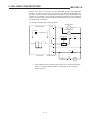
3.3.3
Power supply
The insulation specification of the power module was designed assuming
installation category II. Be sure to use the installation category II power
supply to the PC.
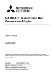
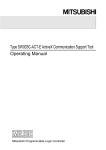
The installation category indicates the durability level against surge voltage
generated by a thunderbolt. Category I has the lowest durability; category
IV has the highest durability.
Category IV
Category III
Category II
Category I
Figure 1. : Installation Category
Category II indicates a power supply whose voltage has been reduced by two
or more levels of isolating transformers from the public power distribution.
3 – 10
3. INSTALLATION
3.3.4
MELSEC-A
Control box
Because the PC is an open device (a device designed to be stored within
another unit), be sure to use it after storing in the control box.
(1)
Electrical shock prevention
In order to prevent persons who are not familiar with the electric facility such as the operators from electrical shocks, the control box must
have the following functions:
(a) The control box must be equipped with a lock so that only the
personnel who has studied about the electric facility and have
enough knowledge can open it.
(b) The control box must have a structure which automatically stops the
power supply when the box is opened.
(2)
Dustproof and waterproof features
The control box also has the dustproof and waterproof functions. Insufficient dustproof and waterproof features lower the insulation
withstand voltage, resulting in insulation destruction. The insulation
in our PC is designed to cope with the pollution level 2, so use in an
environment with pollustion level 2 or below.
Pollution level 1:
An environment where the air is dry and
conductive dust does not exist.
Pollution level 2:
An environment where conductive dust
does not usually exist, but occasional
temporary conductivity occurs due to the
accumulated dust. Generally, this is the
level for inside the control box equivalent
to IP54 in a control room or on the floor of
a typical factory.
Pollution level 3:
An environment where conductive dust
exits and conductivity may be generated
due to the accumulated dust.
An environment for a typical factory floor.
Pollution level 4:
Continuous conductivity may occur due to
rain, snow, etc. An outdoor environment.
As shown above, the PC can realize the pollution level 2 when stored
in a control box equivalent to IP54.
3.3.5
Module installation
(1)
Installing modules contiguously
In AnS series PCs, the left side of each I/O module is left open.
When installing an I/O module to the base, do not make any open
slots between any two modules. If there is an open slot on the left
side of a module with 100/200VAC rating, the printed board which
contains the hazardous voltage circuit becomes bare. When it is unavoidable to make an open slot, be sure to install the blank module
(A1SG60).
When using the A1S5aB expansion base with no power supply, attach
the cover packaged with the expansion base to the side of the leftmost module.
3 – 11
3. INSTALLATION
3.3.6
MELSEC-A
Grounding
There are two kinds of grounding terminals as shown below. Either grounding terminal must be used grounded.
Be sure to ground the protective grounding for the safety reasons.
3.3.7
Protective grounding
: Maintains the safety of the PC and
improves the noise resistance.
Functional grounding
: Improves the noise resistance.
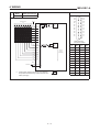
External wiring
(1)
24VDC external power supply
For special modules that require a 24VDC I/O module or external power supply, user a model whose 24VDC circuit is intensively insulated from the hazardous voltage circuit.
(2)
External devices
When a device with a hazardous voltage circuit is externally connected to the PC, use a model whose circuit section of the interface to
the PC is intensively insulated from the hazardous voltage circuit.
(3)
Intensive insulation
Intensive insulation refers to the insulation with the dielectric
withstand voltage shown in table 2.
Table 2: Intensive Insulation Withstand Voltage (Installation
Category II, source: IEC664)
Rated voltage of hazardous voltage area
Surge withstand voltage (1.2/50µs)
150VAC or below
2500V
300VAC or below
4000V
3 – 12
3. INSTALLATION
3.4
MELSEC-A
Module Handling
E CAUTION
Do not disassemble or modify the modules. Doing so could cause trouble,
erroneous operation, injury, or fire.
When wiring, be sure there are no foreign substances such as sawdust or
wiring debris inside the module. Such debris could cause fires, damages, or
erroneous operation.
Tighten the terminal screws with the specified torque. If the terminal screws
are loose, it could result in short circuits, fire, or erroneous operation. If the
terminal screws are too tight, it may cause falling, short circuit or erroneous
operation due to damage of the screws or module.
Install so that the pegs on the bottom of the module fit securely into the base
unit peg holes, and use the specified torque to tighten the module’s fixing
screws. Not installing the module correctry could result in erroneous operation, damage, or pieces of the product falling. If the terminal screws are too
tight, it may cause falling, short circuit or erroneous operation due to damage
of the screws or module.
Do not directry touch the module’s conductive parts or electronic componets.
Doing so could cause erroneous operation or damage of the module.
(1)
Module enclosure, terminal block connectors and pin connectors are
made of resin; do not drop them or subject them to strong impact.
(2)
Do not remove modules’ printed circuit boards from the enclosure in
order to avoid changes in operation.
(3)
During wiring, take care to ensure that wiring off-cuts, etc. do not get
inside the case. If anything does get inside the case, remove it.
(4)
Tighten the module mounting and fixing screws as specified below.
Screw
Tightenig Torque N⋅cm (kg⋅cm) [lb⋅inch]
Module mounting screws (M4)
78 to 118 (8 to 12) [6.9 to 10.4]
I/O module terminal screw (M3.5)
59 to 88 (6 to 9) [5.2 to 7.8]
Power spply module terminal screws (M3.5)
59 to 88 (6 to 9) [5.2 to 7.8]
3 – 13
3. INSTALLATION
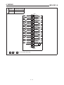
3.5
MELSEC-A
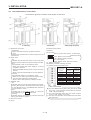
Base Mounting
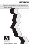
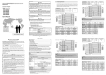
(1)
Mounting dimension
Mounting dimensions of each base unit are as follows:
out
HS
CPU
I/O 0
I/O 1
I/O 3
I/O 2
I/O 4
I/O 5
I/O 6
I/O 7
80626E80G52
MITSUBISHI ELECTRIC CORPORATION
POWER
H
OUT
MADE IN JAPAN E.S.D
A1S38B
WS
W
Dimensions mm (inch)
A1S32B
A1S33B
A1S35B
A1S38B
A1S52B
(S1)
A1S55B
(S1)
A1S58B
(S1)
A1S65B
(S1)
A1S68B
(S1)
W
220
(8.66)
255
(10.04)
325
(12.80)
430
(16.93)
155
(6.10)
260
(10.24)
365
(14.37)
315
(12.40)
420
(16.54)
Ws
200
(7.87)
235
(9.25)
305
(12.01)
410
(16.14)
135
(5.31)
240
(9.45)
345
(13.58)
295
(11.61)
400
(15.75)
H
130 (5.12)
Hs
110 (4.33)
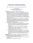
(2)
Base unit mounting position
Provide a clearance between the top and bottom of modules and wall
of structure or components as given below. This is required for ventilation and allows easy replacement of modules.
Main base, Extension base
(A1S5[ ]B(S1),A1S6[ ]B(S1))
30 mm (1.18 inch) or over
Extension base (A5[ ]B, A6[ ]B)
80 mm (3.15 inch) or over
30mm (1.18 inch) or over
Main base
Main base
30 mm (1.18 inch) or over
30mm (1.18 inch) or over
Extension base (A1S5[ ]B(S1),A1S6[ ]B(S1))
Conduit
(50mm (1.97 inch)
or less in height)
30mm (1.18 inch) or
over
30mm (1.18 inch) or over
Extension base (A5[ ]B,A6[ ]B)
80 mm (3.15 inch)
or over
Conduit
(50mm (1.97 inch)
or less in height)
30mm (1.18 inch) or over
80 mm (3.15 inch)
or over
3 – 14
3. INSTALLATION
(3)
MELSEC-A
Unit mounting orientation
(a) Since the PC generates heat, it should be mounted on a well
ventilated location in the orientation shown below.
(b) Do not mount it in either of the orientations shown below.
Flat
Vertical
(4)
Mount base unit on a flat surface. If the mounting surface is not even,
this may strain the printed circuit boards and cause malfunctions.
(5)
Avoid mounting base unit in proximity to vibration sources such as large
magnetic contractors and no-fuse circuit breakers; mount these on a
separate panel or at a distance.
(6)
In order to avoid the effects of radiated noise and heat, provide the
clearances indicated below between the PC and devices that generate
noise or heat (contactors and relays).
Required clearance in front of: at least 100 mm (3.94 inches)
Required clearance on the right and left of <R>: at least 50 mm (1.97
inches)
At least 100 mm
(3.94 inches)
At least 50mm(1.97 inches)
Contactor,
relay, etc.
3 – 15
3. INSTALLATION
(7)
MELSEC-A
If you want to mount base units on a DIN rail, please note the following
points.
(a) Suitable DIN rail types are listed as follows:
TH35-7.5Fe
TH35-7.5Al
TH35-15Fe
*JIS: Japanese Industrial Standard
(b) Spacing intervals for DIN rail mounting screws
When using a TH35-7.5Fe or TH35-7.5Al DIN rail, rail mounting
screws should be placed at a pitch of 200 mm (7.87 inch) or less
in order to ensure that the rail has sufficient strength.
DIN rail
DIN rail mounting screws
35 mm
(1.38 inches)
P
P
P
P=200 mm (7.87 inches) or less
3.6
Constructions to Reduce EMI Noise
The following measures are effective to reduce EMI noise generated
by equipment which contains the AnS products.
(1)
Grouding of a control cabinet
Material of the control cabinet should be steel or equivarent conductor so that radiation of noise is protected. However, if grounding of
the cabinet is not good enough, the cabinet body to which noise is inducted becomes an antenna to radiate noise. Therefore, impedance
of grouding cable of the cabinet should be as low as possible. Use of
a flat braided wire at shortest distance to the earth is recommended
to minimize high frequency impedance.
Door of the cabinet should be also connected to the body low impedance wires.
(2)
Grouding of AnS
Please be aware of the following points for grouding of AnS.
(a) Connect both LG and FG terminal on power supply modules to the
control cabinet at shortest distance. Approx. 20cm.
2
(b) Use thick wire for the earth connections. 2mm or thicker.
3 – 16
3. INSTALLATION
(3)
MELSEC-A
Process signal cables
Please be aware of the following points for process signal cable installations.
(a) Do not install process signal cables with primary voltage lines.
(b) If process cables are installed outside of the cabinet, use of screen
cables is effective for EMI noise reduction.
3.7
Precautions When Unfailure Power System (UPS) is Connected
When Unfailure Power System (abbreviated as UPS hereafter) is connected
to the CPU system, care must be taken on the following matter:
Use a UPS of inverter power supply type at all time with 5% or less voltage
distortion. Do not use a UPS of commercial power supply type.
3 – 17
3. INSTALLATION
3.8
MELSEC-A
Part Identification of the CPU
This section gives the names of each part of the CPU.
(6)
(2)
(1)
(11)
(8)
(11)
(3)
(7)
(9)
(5)
(10)
(4)
A1SCPU(S1)
A2SCPU(S1)
(1) RUN/STOP key switch
A2ASCPU(S1/S30/S60)
(6) Module fixing screws
RUN/STOP:
Used to start/stop sequence program execution.
L.CLR:
Used to clear the data set in the latch range set in the
parameters.
(2) “RUN” LED
ON:
Indicates that the RUN key switch is set to the RUN
position and the sequence program is being executed.
OFF:
The RUN LED is OFF in the following cases:
• When the 100/200 VAC power supply is not being
supplied to the CPU.
(7) Battery
(8) Dip switch
Memory write protect switch ...A1SCPU(S1),
A1SCPUC24-R2
(OFF: Memory not protected,
ON
(ON : Memory write protected)
I/O control switch
(OFF: Refresh mode, ON: Direct mode)
(9) Battery connector
(10) Memory cassette installing connector
(11) Memory write protect Dip switch
• When the RUN/STOP key switch is set to the STOP
position.
• When a remote STOP/PAUSE is currently effective.
Flashing:
The RUN LED flashes in the following cases:
• When an error that stops sequence program operation has been detected in self-diagnosis.
• When a latch clear operation is being executed.
(3) “ERROR” LED
ON:
Indicates that an error has been detected in self-diagnosis. (Note that this LED remains OFF if the setting
for the detected error in the ERROR LED indication
priority settings is “OFF”.)
OFF:
Indicates that no error has occurred, or a fault has
been detected by the CHK instruction.
Flashing:
Indicates that the annunciator (F) has been switched
ON by the sequence program.
(4) RS-422 connector
(5) Cover
3 – 18
Memory Write
Protect Range
(kbytes)
Setting Switch
A2SCPU
A2ASCPU
A2SCPU-S1
A2ASCPUS1/S30/S60
0 to 16
1: ON
1: ON
16 to 32
2: ON
2: ON
32 to 48
3: ON
3: ON
48 to 64
4: ON
4: ON
64 to 80
Unused
5: ON
80 to 96
Unused
6: ON
96 to 112
Unused
7: ON
112 to 144
Unused
8: ON
144 to 256
Unused
9: ON
Latch clear method
1) Turn the RUN/STOP key switch from the “STOP” position to the “L.CLR” position several times to make the
“RUN” LED start flashing.
2) Turn the RUN/STOP switch from the “STOP” position
to the “L.CLR” position once more.
3) The latch clear operation is completed when the “RUN”
LED goes OFF.
3. INSTALLATION
MELSEC-A
MELSEC A1SCPUC24-R2
STOP
L.CLR
RUN
RUN
RESET
ERROR
(12)
RESET
MITSUBISHI
ON
1
(13)
2
BC D
4
E
6
7
2
67
5
F0 1
8 9
3
A
34 5
8
9
(14)
(15)
A1SCPUC24-R2
(12) Transmission specification setting switch
(14) Computer link LED
Transmission specification settings
(factory setting: all OFF)
LED No.
Pisition of Setting Switch
SW
ON
ON
1 2 3 4 5 6 7 8 9
1
0
Setting Items
Write during RUN
enabled/disabled setting
3
2
1
SD
Transmitting
Flashes during data transmission
2
RD
Receiving
Flashes during data receive
3
CPU
Communications with PC CPU
Flashes during communications with
PC CPU
4
NEU
Neutral
Transmission sequence initial state
(waiting for ENQ): ON
ENQ received: OFF
5
ACK
ACK
After sending ACK: ON
After sending NAK: OFF
6
NAK
NAK
After sending NAK: ON
After sending ACK: OFF
7
C/N
Result of PC CPU communications
Error: ON
Normal: OFF
8
P/S
Parity/Sum check error
Error: ON
Normal: OFF
9
PRO
Protocol error
Communications protocol error: ON
Normal: OFF
10
SIO
SIO error
Normal: OFF
3
See *1
4
4
5
Data bit setting
8 bit
7 bit
6
Parity bit setting
Set
Not set
7
Even/odd parity setting
Even
Odd
8
Stop bit setting
2 bit
1 bit
9
Sum check setting
Set
Not set
5
6
7
8
9
*1 Transmission speed setting
Baud rate
(BPS)
RUN
Disabled
2
Transmission speed
setting
0
OFF
1
Enabled
Description
Normal run
Normal: ON
Error: OFF
10
300
600
1200
2400
4800
9600
19200
SW05
OFF
ON
OFF
ON
OFF
ON
OFF
SW06
OFF
OFF
ON
ON
OFF
OFF
ON
SW07
OFF
OFF
OFF
OFF
ON
ON
ON
(13) Mode setting switch
Mode settings (factory setting: 0)
67
F0 1
2
A
BC D
Setting
0
Unusable
1
Protocol 1
2
Protocol 2
3
Protocol 3
4
Protocol 4
(15) RS-232C connector
E
8 9
Mode Setting
Switch Number
34 5
MODE
5
6 to E
F
No-protocol or printer function
Unusable
Used for testing the independent
module
3 – 19
3. INSTALLATION
MELSEC-A
MELSEC A1SHCPU
STOP
LCLR
RUN
ERROR
RUN
RESET
RESET
(16)
MITSUBISHI
(10)
A1SHCPU/A2SHCPU(S1)
(16) Dip switch
A1SHCPU
A2SHCPU
Switch No.
Application
2
Memory write protect setting (RAM and E 2 PROM)
ON: With memory write protection *1
OFF: Without memory write protection
1
I/O select switch setting
ON: Direct method
OFF: Refresh method
Switch No.
5
Application
I/O switch setting
ON: Direct method
OFF: Refresh method
I/O select switch setting
ON: With memory write protection *1
OFF: Without memory write protection
Memory write protection range
1 2 3 4 5 6 7 8 9 10
A2SHCPU-S1
ON
OFF
4
48 to 64k bytes
3
32 to 48k bytes
2
16 to 32k bytes
1
0 to 16k bytes
Switch No.
10
Application
I/O select switch setting
ON: Direct method
OFF:Refresh method
Memory write protect setting (RAM and E 2 PROM)
ON: With memory write protection *1
OFF:Without memory write protection
Memory write protection range
9
144 to 192k bytes
8
112 to 144k bytes
7
96 to 112k bytes
6
80 to 96k bytes
5
64 to 80k bytes
4
48 to 64k bytes
3
32 to 48k bytes
2
16 to 32k bytes
1
0 to 16k bytes
*1 When installing the memory cassette, the setting becomes invalid to
RAM only.
3 – 20
3. INSTALLATION
3.9
MELSEC-A
RS232C Interface (A1SCPUC24-R2 only)
(1)
1
2
3
4
5
RS-232C connector specificatins
Pin
Number
Signal
Abbreviation
1
CD
2
RD(RXD)
Receive data
3
SD(TXD)
Send data
4
DTR(ER)
Data terminal ready
5
SG
Signal ground
6
DSR(DR)
Data set ready
7
RS(RTS)
Request to send
8
CS(CTS)
Clear to send
6
7
8
9
Signal Name
Signal Direction
A1SCPUC24-R2 ↔ External Device
Receive carrier detection
A 9-pin D subconnector is supplied in the same package as the A1SCPUC24R2 body.
Product name
9-pin Dsub (male), screw mounted
17JE-23090-02-D8A, made by DDK
(2)
RS-232C cable
For the RS-232C cable, use a cable that conforms to the RS-232C
standard and is no longer than 15 m.
(Recommended cable)
(3)
7/0. 127[ ]P HRV-SV............(RS-232C cable made by Oki Densen)
Specify the number of wire pairs.
For example, if the number of pairs is thirteen:
7/0. 127 13P HRV-SV
Connecting the RS-232C connectors
The standard method for connecting the RS-232C connectors is shown
below.
For details on the connection method, refer to the Computer Link Module
User’s Manual (Com. link func./Print func.).
(a) Example connection to an external device in which the CD signal
(pin No.8) can be switched ON and OFF.
A1SCPUC24-R2
Cable
Connections and
Signal Directions
External Device
Signal Names
Pin Number
CD
1
CD
RD(RXD)
2
RD(RXD)
SD(TXD)
3
SD(TXD)
DTR(ER)
4
DTR(ER)
SG
5
SG
DSR(DR)
6
DSR(DR)
RS(RTS)
7
RS(RTS)
CS(CTS)
8
CS(CTS)
3 – 21
Signal Names
3. INSTALLATION
MELSEC-A
(b) Example connection to an external device in which the CD signal
(pin No.8) cannot be switched ON and OFF.
In the case of a connection to a device in which the device’s CD
signal cannot be switched ON and OFF, set non-execution of the
buffer memory address 10BH RS232C CD terminal check.
1) Example connection to an external device in which DC code
control or DTR/DSR code control is executed.
A1SCPUC24-R2
Cable
Connections and
Signal Directions
External Device
Signal Names
Pin Number
Signal Names
CD
1
CD
RD(RXD)
2
RD(RXD)
SD(TXD)
3
SD(TXD)
DTR(ER)
4
DTR(ER)
SG
5
SG
DSR(DR)
6
DSR(DR)
RS(RTS)
7
RS(RTS)
CS(CTS)
8
CS(CTS)
2) Example connection to an external device in which DC code
control is executed.
A1SCPUC24-R2
Cable
Connections and
Signal Directions
External Device
Signal Names
Pin Number
CD
1
CD
RD(RXD)
2
RD(RXD)
SD(TXD)
3
SD(TXD)
DTR(ER)
4
DTR(ER)
SG
5
SG
DSR(DR)
6
DSR(DR)
RS(RTS)
7
RS(RTS)
CS(CTS)
8
CS(CTS)
3 – 22
Signal Names
3. INSTALLATION
MELSEC-A
3.10 Self-Loopback Test (A1SCPUC24-R2 only)
The self-loopback test checks whether or not the isolated A1SCPUC24-R2
(not connected to any external devices) will operate correctly.
For details on the self-loopback test, refer to the Computer Link Module
User’s Manual (Com. link func./Printer func.).
Connect the cables
• Connect cables to the RS-232C connectors.
Pin
Signal
Number Abbreviation
1
2
3
4
5
6
7
8
9
Signal Name
Cable Connections
Receive carrier detection
1
CD
2
RD(RXD)
Receive data
3
SD(TXD)
Send data
4
DTR(ER)
Data terminal ready
5
SG
Signal ground
6
DSR(DR)
Data set ready
7
RS(RTS)
Request to send
8
CS(CTS)
Clear to send
Set the mode setting switch
• Set the mode setting switch to “F”.
Execute the self-loopback test
• Turn the PC CPU power supply ON or reset the PC CPU.
Check the LED display status
Check Item
Display When Normal
PC CPU communications
check
RS-232C communications
check
C/N
OFF
CPU
Flicker
SIO
OFF
SD
RD
Completed
• Turn the power supply OFF.
3 – 23
Flicker
Display in Error Status
C/N
(LED No.7)
ON
SIO
(LED No.10)
ON
4. WIRING
MELSEC-A
4.
WIRING
4.1
General Safety Requirements
P DANGER
All external power supply must be turned off during installation and wiring.
Unless all phases are cut off from the products, it could cause electrical
shock or damage on the products.
Before connecting the power to the products, put terminal covers back
onto the terminals.
Otherwise, it could cause electrical shock.
A protective earth terminal which is marked with “
ted to the earth.
Otherwise, it could cause electrical shock.
(LG)” must be connec-
All electrical connections should be carried out by trained and competent
personnel, and must comply with the requirements of all relevant local and
national wiring regulations for installation wiring.
Particular attention is required when preparing the installation wiring for
connection to terminal to ensure that hazardous live wiring are adequately
separated from the Safety Extra Low Voltage wiring.
All external power supplies and signals connected to other devices or
equipment, of which rated voltage is 24 V or lower, should not compromise
the Safety Extra Low Voltage requirements.
E
A readily accessible switch or circuit breaker should be included in the
equipment which contains the product so that the power supply for the product can be disconnected if necessary.
CAUTION
Rated voltage and terminal assignment of each module should be confirmed before wiring is carried out. Connection of different voltage or wrong
connection could cause fire and/or malfunction of the products.
Do not supply 24 VDC power
supply from more than one power
supply modules in parallel to one
I/O module. If they are connected
so, the power supply modules will
become not and could be caused
fire and/or malfunction.
24 VDC
24 VDC
External power supply
Terminal screws should be tighten by the specified torque. Loose connection could cause short-circuit, fire and/or malfunction of the products.
During wiring, be sure that no off-cut of wires or other conductive dusts go
into modules. It could cause fire, malfunction and/or failure of the products.
Wiring for modules which provide connector for external wiring should be
securely carried out with the specified tools or by soldering. Unsecured
connection could cause short-circuit, fire, and/or malfunction of the products.
4–1
4. WIRING
MELSEC-A
Do not place process control signal cables and/or communication cables
nearby main power cables or actuation power cables so that risk of noise
trouble can be minimized. It is recommended to keep a distance of 100
mm or more between those cables.
4.2
Power Supply Modules
(1)
Terminal assignment
(a) A1S61P
A1S61P
FG
SHORT 100VAC
Terminal
Name
Wiring Instructions
INPUT
AC100/200V
Connect 100 to 120/200 to 240 VAC
power supply wires to these terminals.
Either terminal can be connected to
either live or neutral line.
SHORT 100VAC
OPEN 200VAC
These are voltage selection terminals.
Short the terminals for 100 to 120
VAC input, and open them for 200 to
240 VAC input.
LG
This is a functional earth terminal to
be connected to the noise free earth.
WARNING: If this terminal is not
connected to the earth, the terminal
holds half of the supplied voltage.
FG
This is a functional earth terminal to
be connected to the noise free earth.
OPEN 200VAC
LG
INPUT
100/200VAC
(b) A1S61PEU
Terminal
Name
A1S61PEU
INPUT 200
to 240 VAC
(LG)
(FG)
(LG)
Wiring Instructions
Connect 200 to 240 VAC power supply
wires to these terminals.
Either terminal can be connected to
either live or neutral line.
This is a protective earth terminal to
be connected to the earth.
WARNING: This terminal must be
connected to the earth, otherwise,
the secondary circuit cannot be
ensured as safe.
INPUT
200 to 240VAC
4–2
(FG)
This is a functional earth terminal to
be connected to the noise free earth.
4. WIRING
MELSEC-A
(c) A1S61PN
Terminal
Name
A1S61PN
INPUT 100
to 240 VAC
NC
NC
(LG)
(FG)
(LG)
Wiring Instructions
Connect 100 to 240 VAC power supply
wires to these terminals.
Either terminal can be connected to
either live or neutral line.
This is a protective earth terminal to
be connected to the earth.
WARNING: This terminal must be
connected to the earth, otherwise,
the secondary circuit cannot be
ensured as safe.
INPUT
100 to 240VAC
(FG)
NC
This is a functional earth terminal to
be connected to the noise free earth.
No Connectable
(d) A1S62P
A1S62P
Terminal
Name
Wiring Instructions
INPUT
100/200VAC
Connect 100 to 120/200 to 240 VAC
power supply wires to these terminals.
Either terminal can be connected to
either live or neutral line.
SHORT 100VAC
OPEN 200VAC
These are voltage selection terminals.
Short the terminals for 100 to 120
VAC input, and open them for 200 to
240 VAC input.
LG
This is a functional earth terminal to
be connected to the noise free earth.
WARNING: If this terminal is not
connected to the earth, the terminal
holds half of the supplied voltage.
FG
This is a functional earth terminal to
be connected to the noise free earth.
+24V
24G
These are output terminals of 24 VDC
service power which can be used as
I/O load power and/or other purposes.
+24V
24G
FG
SHORT 100VAC
OPEN 200VAC
LG
INPUT
100/200VAC
4–3
4. WIRING
MELSEC-A
(e) A1S62PEU
Terminal
Name
A1S62PEU
INPUT 200
to 240 VAC
+24V
24G
(LG)
(FG)
(LG)
Wiring Instructions
Connect 200 to 240 VAC power supply
wires to these terminals.
Either terminal can be connected to
either live or neutral line.
This is a protective earth terminal to
be connected to the earth.
WARNING: This terminal must be
connected to the earth, otherwise,
the secondary circuit cannot be
ensured as safe.
INPUT
200 to 240 VAC
(FG)
+24V
24G
This is a functional earth terminal to
be connected to the noise free earth.
These are output terminals of 24 VDC
service power which can be used as
I/O load power and/or other purposes.
(f) A1S62PN
Terminal
Name
A1S62PN
INPUT 100
to 240 VAC
Wiring Instructions
Connect 100 to 240 VAC power supply
wires to these terminals.
Either terminal can be connected to
either live or neutral line.
+24V
24G
(FG)
(LG)
(LG)
INPUT
100 to 240VAC
(FG)
+24V
24G
This is a protective earth terminal to
be connected to the earth.
WARNING: This terminal must be
connected to the earth, otherwise,
the secondary circuit cannot be
ensured as safe.
This is a functional earth terminal to
be connected to the noise free earth.
These are output terminals of 24 VDC
service power which can be used as
I/O load power and/or other purposes.
(g) A1S63P
Terminal
Name
A1S63P
INPUT
+24V
24G
Connect 24 VDC power supply wires
to these terminals.
A 24 VDC SELV power supply is
required.
LG
This is a functional earth terminal to
be connected to the noise free earth.
FG
This is a functional earth terminal to
be connected to the noise free earth.
NC
No Connectable
NC
NC
FG
NC
NC
LG
+24V
INPUT
24G
SELV power supply
Functional earth
4–4
Wiring Instructions
4. WIRING
MELSEC-A
(2)
Take following measures so that electrical noise is minimized.
(a) Provide separate wiring for the PC power, I/O devices, and other
operating devices as shown below. Further more, insert an isolated
transformer if intensive noise is expected.
Main power
supply
PC power
supply
Isolation transformer
200 to 240 VAC
PC
I/O power
supply
Control devices
Main power
supply
Main power devices
(b) Power supply wires should be twisted as tightly as possible, and
connect to power supply modules at the shortest distance. To
minimize voltage drop, use wires as thick as possible.
(c) As a measure against lightning surges, insert surge absorbers as
shown below.
PC I/O
devices
AC power source
E2
E1
E1
Lightning surge absorber
POINTS
(1) Provide separator grounding for the lightning surge absorber (E1) and
for the PC (E2).
(2) Select a lightning surge absorber of which maximum allowable line
voltage is higher than input voltage of the power supply module.
4.3
Digital I/O Modules
The following instructions should be observed for I/O module wiring.
(1)
I/O signal wires must be installed at least 100 mm (3.94 inch) away from
high-voltage and large-current main power wires so that noise induction
from such high power circuit is minimized.
(2)
If the I/O signal wires cannot be separately installed from the high power
wires, use shielded cables for I/O signal and connect their shield to the
earth.
4–5
4. WIRING
4.3.1
MELSEC-A
Input module connections
Rated Input
Voltage
Model
Model
Rated Input Voltage
(2)
A1SX30
12/24 VAC/DC
A1SX10
100 to 120 VAC
(1)
A1SX10EU
X01
A1SX20
200 to 240 VAC
1
2
3
4
5
6
7
8
9
10
11
12
13
14
15
16
17
18
19
20
X03
X05
X07
X08
X0A
X0C
X0E
COM
1
3
4
5
6
X07 8 7
9
X08
10
11
X0A 12
13
X0C
14
X0E 16 15
17
COM
18
19
20
X03
X05
A1SX20EU
X01
2
X00
X02
X04
X06
COM
X09
X0B
X0D
X0F
+
-
-
+
X00
X02
X04
X06
COM
X09
X0B
X0D
X0F
9 and 18 are connected internally.
9 and 18 are connected internally.
P DANGER
Do not touch terminals while the power is
supplied.
Model
(3)
A1SX40
Model
Rated Input Voltage
12/24 VDC
(4)
A1SX80
12/24 VDC
A1SX80-S1
A1SX40-S1
24 VDC
24 VDC
A1SX80-S2
A1SX40-S2
X01
X03
X05
X07
X08
2
4
6
8
10
X0A
12
X0C
14
X0E
- +
Rated Input Voltage
COM
16
18
20
1
3
5
7
9
11
13
15
17
X00
1
2
3
X03
4
5
X05
6
X07 8 7
9
X08
10
11
X0A 12
X0C 14 13
X0E 16 15
17
COM
18
19
20
X01
X02
X04
X06
COM
X09
X0B
X0D
X0F
+ -
19
- +
X00
X02
X04
X06
COM
X09
X0B
X0D
X0F
9 and 18 are connected internally.
9 and 18 are connected internally.
4–6
4. WIRING
Model
MELSEC-A
Rated Input Voltage
Model
Rated Input Voltage
(6)
(5)
A1SX41
12/24 VDC
A1SX41-S2
24 VDC
A1SX42
12/24 VDC
X00
A1SX42-S2
24 VDC
X01
A1SX71
5/24 VDC
X02
X03
X00
X01
X02
X03
X04
X05
X06
X07
X08
X09
X0A
X0B
B19 A19
B18 A18
B17 A17
B16 A16
B15 A15
B14 A14
B13 A13
B12 A12
B11 A11
B10 A10
X10
X04
X11
X05
X12
X06
X13
X07
X14
X08
X15
X09
X16
X0A
X17
X0B
B6
A6
B5
A5
Vacant
B4
A4
Vacant
Vacant
B3
A3
Vacant
B2
A2
Vacant
B1
A1
Vacant
X0E
X0F
COM
COM
X18
B12 A12
X19
B11 A11
X1A
B10 A10
X1B
A6
B5
A5
Vacant
B4
A4
Vacant
Vacant
B3
A3
Vacant
B2
A2
Vacant
B1
A1
X0F
X1C
X1E
X17
B13 A13
B6
X0E
X1D
X16
B14 A14
A7
X1B
A7
X15
B15 A15
B7
X0D
B7
X0D
X14
B16 A16
A8
X1A
A8
X13
B17 A17
B8
X0C
B8
X12
B18 A18
A9
X19
A9
X11
B19 A19
B9
X18
B9
X0C
- +
B20 A20
X10
B20 A20
- +
COM
X1F
COM
X1C
X1D
X1E
X1F
Vacant
*1 The figure above shows the connections
for the open collector (sink) type.
B1 and B2 are connected internally.
•
*1 The figure above indicates F (the first half
32 points).
The connections for L (the latter half 32
points) are the same as for F (regard X00
to X1F as X20 to X3F.)
B1 and B2 are connected internally.
TTL, LS-TTL, CMOS buffer (sink)
connection
B20
+
-
B2
•
*2 The A and B pin number rows shown
above are transposed with respect to the
diagram of the A and B rows which is
printed on the module. Remember that the
A row pin numbers correspond to the B
row of the module.
Sensor (source) connection
B20
+ -
B2
*2 The A and B pin number rows shown
above are transposed with respect to the
diagram of the A and B rows which is
printed on the module. Remember that the
A row pin numbers correspond to the B
row of the module.
4–7
4. WIRING
Model
(7)
MELSEC-A
Rated Input Voltage
A1SX81
12/24 VDC
A1SX81-S2
24 VDC
1
X01
2
X03
X02
21
3
X05
X04
22
4
X07
X06
23
5
X09
X08
24
6
X0B
X0A
25
7
X0D
26
X0F
27
8
9
X11
X0C
X0E
X10
28
10
X13
X12
29
11
X15
X14
30
12
X17
•
X00
20
X16
31
13
X19
32
X1B
33
X1D
34
X1F
35
COM
36
Vacant
37
14
15
16
17 , 18 and 36 are connected internally.
4–8
X18
X1A
X1C
X1E
17
COM
-
+
18
COM
+
-
19
Vacant
4. WIRING
Model
MELSEC-A
Pin Arrangement
Rated Input Voltage
(8)
A1S42X
12/24 VDC
Input terminals
Pin No.
Internal
control
circuit
R
X38 X30 X28 X20 X18 X10 X08 X00
R
B12
A12
B11
A11
B10
A10
B9
A9
B8
A8
B7
A7
B12
XD0
A12
XD1
B6
A6
B11
XD2
B5
A5
B4
A4
B3
A3
B2
A2
B1
A1
X39 X31 X29 X21 X19 X11 X09 X01
X3A X32 X2A X22 X1A X12 X0A X02
X3B X33 X2B X23 X1B X13 X0B X03
A11
XD3
X3C X34 X2C X24 X1C X14 X0C X04
B10
XD4
A10
XD5
B9
XD6
A9
XD7
B8
XSCN0
A8
XSCN1
B7
XSCN2
A7
XSCN3
B6
XSCN4
A6
X3D X35 X2D X25 X1D X15 X0D X05
X3E X36 X2E X26 X1E X16 X0E X06
X3F X37 X2F X27 X1F X17 X0F X07
Seen from front
face of the module
Internal
control
circuit
R
Pin
No.
Signal
Name
Pin
No.
Signal
Name
B12
XD0
A12
XD1
B11
XD2
A11
XD3
B10
XD4
A10
XD5
XSCN5
B9
XD6
A9
XD7
B5
XSCN6
B8
XSCN0
A8
XSCN1
A5
XSCN7
B7
SXCN2
A7
XSCN3
B6
XSCN4
A6
XSCN5
B5
XSCN6
A5
XSCN7
B4
Vacant
A4
Vacant
B3
12/24
VDC
A3
12/24
VDC
B2
0V
A2
0V
B1
FG
A1
FG
Internal
scan at
1/8th duty
B3, A3
12/24 VDC
B2, A2
*1
If there will be cases where two or more switches
are pressed simultaneously, install a diode at each
switch (see right).
4–9
4. WIRING
4.3.2
MELSEC-A
Output module connections
Model
Model
Rated Load Voltage
A1SY10
A1SY10EU
240 VAC, 24 VDC
L
L
L
L
L
L
L
L
Y01
Y03
Y05
Y07
Y08
Y0A
Y0C
Y0E
COM2
Y00
1
2
3
4
12
14
16
18
20
Y06
7
8
10
Y04
5
6
L
Y02
L
L
L
L
L
L
COM1
9
11
Y09
13
Y0B
15
17
L
L
L
L
Y0D
L
L
Y0F
L
+ -
19
Rated Load Voltage
(2)
(1)
Do not touch terminals while the power is
supplied.
2
4
6
8
10
L
Y0E
Y09
11
Y0A
12
L
Y0B
13
14
L
Y0D
15
16
COM2
L
COM1
9
Y08
L
Y06
7
Y07
L
Y04
5
Y05
L
Y02
3
Y03
Y0C
Y00
1
Y01
L
24 VDC
(For relay drive)
P DANGER
120 VAC, 24 VDC
L
Y0F
17
L
18
+ -
19
20
24 VDC
(For relay drive)
P DANGER
Do not touch terminals while the power is
supplied.
Model
Model
Rated Load Voltage
Rated Load Voltage
(3)
A1SY14EU
(4)
240 VAC, 24 VDC
A1SY18A
240 VAC,24 VDC
A1SY18AEU
L
L
L
L
Y01
Y03
Y04
Y06
COM2
L
L
Y09
Y0B
2
4
6
8
10
12
14
16
18
20
1
3
5
7
9
11
13
15
Y00
Y02
L
L
Y00
COM1
Y05
Y07
Y08
Y0A
Y01
L
Y02
L
Y03
L
L
Y04
Y05
COM3
Y06
Y07
17
19
+ -
2
4
6
8
10
12
14
16
18
24 VDC
(For relay drive)
20
1
3
5
7
9
11
13
15
17
Y00
Y01
Y02
Y03
Y04
Y05
Y06
Y07
L
L
L
L
L
L
L
L
+ -
19
24 VDC
(For relay drive)
P DANGER
P DANGER
Do not touch terminals while the power is
supplied.
Do not touch terminals while the power is
supplied.
4 – 10
4. WIRING
Model
MELSEC-A
Rated Load Voltage
Model
(5)
Rated Load Voltage
(6)
A1SY22
100/200 VAC
1
Y01
L
2
Y03
L
4
5
Y05
L
6
7
Y07
L
100/200 VAC
Y08
L
Y0A
L
Y0C
L
Y0E
L
100/200 VAC
3
8
9
10
11
12
13
14
15
16
18
17
19
A1SY28A
Y00
100/200 VAC
L
Y02
Y04
Y06
L
Y00
L
Y01
L
Y02
COM1
Y03
Y09
L
Y0B
Y04
L
Y0D
Y0F
Y05
L
Y06
L
Y07
COM2
1
2
3
4
6
7
8
10
12
14
16
18
20
5
9
11
13
15
Y00
Y01
Y02
Y03
Y04
Y05
Y06
Y07
L
L
L
L
L
L
L
L
17
19
20
P DANGER
Do not touch terminals while the power is
supplied.
Model
Do not touch terminals while the power is
supplied.
4
1
A1SY40
3
5
6
7
8
9
10
11
12
14
13
15
16
Y00
Y01
Y02
Y03
Y04
Y05
Y06
Y07
Rated Load Voltage
(8)
100-240 VAC
2
DANGER
Model
Rated Load Voltage
(7)
A1SY28EU
P
L
L
L
L
L
L
L
L
12/24 VDC
Y01
Y03
Y05
Y07
L
COM
L
Y08
L
L
L
L
L
17
L
18
Y0A
Y0C
Y0E
COM
19
20
P DANGER
Do not touch terminals while the power is
supplied.
4 – 11
1
2
3
4
5
6
7
8
9
10
12
11
13
14
15
16
18
20
17
19
Y00
Y02
Y04
Y06
L
L
L
L
12/24 VDC
Y09
Y0B
Y0D
Y0F
12/24 VDC
L
L
L
L
4. WIRING
Model
MELSEC-A
Rated Load Voltage
Model
Rated Load Voltage
(10)
(9)
A1SY50
12/24 VDC
A1SY60
24 VDC
A1SY60E
Y01
L
1
Y01
L
2
3
Y03
L
4
5
Y05
L
6
7
Y07
L
8
COM
Y08
L
12
14
Y0C
L
Y0E
L
15
16
18
COM
Model
11
13
Y0A
L
9
10
20
17
19
Y00
L
L
Y04
L
0V
Y06
L
12/24 VDC
Y09
Y0B
Y0D
+ -
Y01
+ -
Y02
+ -
Y03
L
L
L
L
Y04
Y05
Y06
Y07
Vacant
Vacant
1
2
3
4
6
8
10
5
7
9
11
12
13
14
16
18
20
15
Y00
Y01
Y02
Y03
L
L
L
L
+ -
*
3
4
5
6
7
8
9
10
11
12
13
14
15
16
17
18
19
Y02
L
Y04
L
Y06
L
+ -
COM1
12/24 VDC
L
Y08
Y0A
For a load
voltage of
5 VDC.
L
Y0C
L
Y0E
L
+ -
COM1
20
For a load
voltage of
12/24 VDC.
L
12/24 VDC
When using a working load voltage of 5 VDC,
a separate 12/24 VDC source is required for the
external power supply.
Model
L
Rated Load Voltage
(12)
L
For sink
L
L
L
L
L
L
+ -
19 Vacant
0V
A1SY80
Y05
17 Vacant
Y0F
2
Y00
5 VDC
12/24 VDC
Y04
Y07
Y0D
1
L
+ -
Y06
Y0B
L
L
Y0F
Y09
L
5/12/24/48 VDC
Y00
Y07
L
Rated Load Voltage
+ -
Y05
L
Y02
(11)
A1SY68A
Y03
L
5/12/24 VDC
12/24 VDC
Y01
Y03
Y05
Y07
0V
L
+ -
L
+ -
L
For source
4 – 12
L
Y09
Y0B
Y0D
Y0F
0V
1
2
4
3
5
6
7
8
9
10
11
12
13
14
15
16
17
18
19
20
Y00
L
Y02
L
Y04
L
Y06
COM1
L
+
Y08
L
Y0A
L
Y0C
L
Y0E
COM1
-
L
+
-
4. WIRING
Model
MELSEC-A
Rated Load Voltage
Model
(13)
Rated Load Voltage
(14)
A1SY41
L
L
L
L
L
L
L
L
L
12/24 VDC
Y00
Y01
Y02
Y03
Y04
Y05
Y06
Y07
Y08
A1SY42
B20 A20
B19 A19
B18 A18
B17 A17
B16 A16
B15 A15
B14 A14
B13 A13
B12 A12
Y10
Y11
Y12
Y13
Y14
Y15
Y16
Y17
Y18
L
L
L
L
L
L
L
L
L
L
L
L
L
L
L
L
L
L
L
L
L
L
L
L
L
Y09
Y0A
Y0B
Y0C
Y0D
Y0E
Y0F
B11 A11
B10 A10
B9
A9
B8
A8
B7
A7
B6
A6
B5
A5
Y19
Y1A
Y1B
Y1C
Y1D
Y1E
Y1F
Vacant
B4
A4
Vacant
Vacant
B3
A3
Vacant
B2
A2
12/24 VDC
12/24 VDC
B1
A1
COM
L
L
L
L
L
L
L
L
L
L
L
L
L
L
12/24 VDC
- +
12/24 VDC
Y00
Y01
Y02
Y03
Y04
Y05
Y06
Y07
Y08
Y09
Y0A
Y0B
Y0C
Y0D
Y0E
Y0F
*2 The A and B pin number rows shown
above are transposed with respect to the
diagram of the A and B rows which is
printed on the module. Remember that the
A row pin numbers correspond to the B row
of the module.
B18 A18
B17 A17
B16 A16
B15 A15
B14 A14
B13 A13
B12 A12
B11 A11
B10 A10
B9
B8
B7
B6
A9
A8
A7
A6
A5
Vacant
B4
A4
Vacant
B3
A3
12/24 VDC
*1 B1 and B2 , and A1 and A2 are
connected internally.
B19 A19
B5
12/24 VDC
COM
B20 A20
B2
A2
B1
A1
Y10
Y11
Y12
Y13
Y14
Y15
Y16
Y17
Y18
Y19
Y1A
Y1B
Y1C
Y1D
Y1E
Y1F
L
L
L
L
L
L
L
L
L
L
L
L
L
L
L
L
Vacant
Vacant
COM
12/24 VDC
- +
COM
*1 The figure above indicates F (the first half
32 points).
The connections for L (the latter half 32
points) are the same as for F (regard Y00
to Y1F as Y20 to Y3F.)
B1 and B2 , and A1 and A2 , are
connected internally.
*2 The A and B pin number rows shown
above are transposed with respect to the
diagram of the A and B rows which is
printed on the module. Remember that the
A row pin numbers correspond to the B
row of the module.
4 – 13
4. WIRING
Model
MELSEC-A
Model
Rated Load Voltage
(15)
A1SY71
L
L
L
L
L
L
L
L
L
L
L
L
L
L
L
L
(16)
5/12 VDC
Y00
Y01
Y02
Y03
Y04
Y05
Y06
Y07
Y08
Y09
Y0A
Y0B
Y0C
Y0D
Y0E
Y0F
B20 A20
B19 A19
B18 A18
B17 A17
B16 A16
B15 A15
B14 A14
B13 A13
B12 B12
B11 A11
B10 A10
B9
A9
B8
A8
B7
A7
B6
A6
B5
A5
Y10
Y11
Y12
Y13
Y14
Y15
Y16
Y17
Y18
Y19
Y1A
Y1B
Y1C
Y1D
Y1E
Y1F
B4
A4
Vacant
Vacant
B3
A3
Vacant
B2
A2
B1
A1
5/12 VDC
L
L
L
L
L
L
L
L
L
L
L
L
L
L
L
L
L
L
L
L
L
L
L
L
L
L
L
L
L
L
L
12/24 VDC
Y01
Y03
Y05
Y07
Y09
Y0B
Y0D
Y0F
Y11
Y13
Y15
Y17
Y19
Y1B
Y1D
Y1F
COM
Vacant
5/12 VDC
L
A1SY81
A1SY81EP
Rated Load Voltage
COM
0V
-
1
2
21
3
22
4
Y02
L
Y04
Y06
L
L
L
23
5
24
6
25
7
26
8
27
9
28
10
29
11
30
12
Y08
Y0A
Y0C
Y0E
Y10
Y12
Y14
Y16
L
L
L
L
L
L
L
L
31
13
32
14
33
15
34
16
Y18
Y1A
Y1C
Y1E
L
L
L
L
35
17
COM
36
18
COM
37
19
+
Y00
20
0V
COM
•
*1 B1 and B2 , and A1 and A2 , are
connected internally.
*2 The A and B pin number rows shown
above are transposed with respect to the
diagram of the A and B rows which is
printed on the module. Remember that the
A row pin numbers correspond to the B row
of the module.
4 – 14
17 and 18 and 36 , and 19 and 37 are
connected internally.
4. WIRING
Model
MELSEC-A
Pin Arrangement
Rated Load Voltage
(17)
A1S42Y
12/24 VDC
A1S42Y
B12
B11
B10
B9
B8
B7
B6
B5
B4
B3
B2
B1
Output terminals
Pin No.
*3
Resistors to limit
LED current
R
A12
A11
A10
A9
A8
A7
A6
A5
A4
A3
A2
A1
Seen from front
face of the module
R
R
Internal
scanning at
1/8th duty
Pin
No.
Signal
Name (FH)
Pin
No.
Signal
Name (FH)
B12
YD0
A12
YD1
B11
YD2
A11
YD3
B10
YD4
A10
YD5
B9
YD6
A9
YD7
B8
YSCN0
A8
YSCN1
B7
YSCN2
A7
YSCN3
B6
YSCN4
A6
YSCN5
B5
YSCN6
A5
YSCN7
B4
Vacant
A4
Vacant
B3
12/24 VDC
A3
12/24 VDC
B2
0V
A2
0V
B1
Vacant
A1
Vacant
12/24 VDC
*1
*2
The fuse in the output module is provided to prevent the
external wiring from burning in the event of a short circuit in the
module’s output. Consequently, it may not be able to protect
output devices.
If an output device is damaged in a failure mode other than a
short circuit, the fuse might not be blown.
The “ERR.” LED will also come ON when the external power
supply is cut.
*3
*4
4 – 15
Mount the resistors to limit LED current
externally to the A1S42Y.
The power supply voltage (12/24 VDC) is applied in the LED’s
reverse direction.
If the peak inverse voltage is insufficient, connect protective
diodes in series with each of the LEDs.
4. WIRING
4.3.3
MELSEC-A
Input/output composite module connections
Model
Rated Input Voltage
Rated Load Voltage
12/24 VDC
12/24 VDC
(1)
A1SH42
X00
X01
X02
X03
X04
X05
X06
X07
X08
X09
X0A
X0B
X0C
X0D
X0E
X0F
Vacant
Vacant
- +
COM
COM
B20 A20
B19 A19
B18 A18
B17 A17
B16 A16
B15 A15
B14 A14
B13 A13
B12 A12
B11 A11
B10 A10
B9
B8
B7
B6
A9
A8
A7
A6
X10
X11
L
X12
L
X13
L
X14
L
X15
L
X16
L
X17
L
X18
L
X19
L
X1A
L
X1B
L
X1C
L
X1D
L
X1E
L
X1F
B5
A5
B4
A4
Vacant
A3
Vacant
B3
L
L
Y00
Y01
Y02
Y03
Y04
Y05
Y06
Y07
Y08
Y09
Y0A
Y0B
Y0C
Y0D
Y0E
Y0F
B18 A18
B17 A17
B16 A16
B15 A15
B14 A14
B13 A13
B12 A12
B11 A11
B10 A10
B9
B8
B7
B6
A9
A8
A7
A6
A5
Vacant
B4
A4
Vacant
B3
A3
A2
Vacant
12/24 VDC
B1
A1
Vacant
12/24 VDC
*1 B1 and B2 are connected internally.
B19 A19
B5
B2
F (Input side)
B20 A20
B2
A2
B1
A1
Y10
Y11
Y12
Y13
Y14
Y15
Y16
Y17
Y18
Y19
Y1A
Y1B
Y1C
Y1D
Y1E
Y1F
L
L
L
L
L
L
L
L
L
L
L
L
L
L
L
L
Vacant
Vacant
COM
12/24 VDC
- +
COM
L (Output side)
*3 B1 and B2 , and A1 and A2 , are
connected internally.
*2 The A and B pin number rows shown above are transposed with respect to the diagram of
the A and B rows which is printed on the module. Remember that the A row pin numbers
correspond to the B row of the module.
4 – 16
4. WIRING
Model
MELSEC-A
Rated Input Voltage
Rated Load Voltage
24 VDC
24 VDC/240 VAC
(2)
A1SX48Y18
P DANGER
Do not touch terminal while the power is supplied.
Model
Rated Input Voltage
Rated Load Voltage
24 VDC
12/24 VDC
(3)
A1SX48Y58
4 – 17
5. FAIL-SAFE CONSTRUCTIONS
5.
FAIL-SAFE CONSTRUCTIONS
5.1
General Safety Requirements
MELSEC-A
P DANGER
Safety circuitry must be so designed and constructed externally that an entire system stays in safe in case of a external power supply failure and/or
PC failure. In particular, the following safety circuitry are required to constructed outside of the PC.
(1)
Emergency stop circuit, protection circuit, interlocking circuit for contrary operations such as forward and reverse movement, and hardware
stroke limit circuit for positioning controls must be constructed externally.
(2)
In case of hardware failure which PC CPU cannot detect occurs, all or
some output signals could be turned on without program instructions.
An external safety circuitry must be so constructed that safety of equipment or machine can be protected from such case.
Please refer to Sub-clause 5.2 for details.
(3)
In some cases, relays or transistors used in output modules stay always
ON or OFF as failure symptoms. If such failure could cause serious
damage on persons or properties, those safety critical output signals
must be externally monitored.
If the power to the PC is turned ON after turning ON the external power
supply used for the process control with the DC output module, the DC output module may make an erroneous output for an instant. Take the following procedures for power up of the equipment, in order to prevent such
erroneous input and output to/from the PC.
5.2
(1)
Turn ON the power to the PC.
(2)
Turn ON the external power supply used for the process control.
(3)
Turn ON the START switch.
(4)
Turn ON the power to the output devices by using a program.
(5)
Confirm that all external power supplies are turned ON, and then, an I/O
control program should be executed.
Fail-Safe Circuitry Against to Failure of the PC
Though Mitsubishi PCs are manufactured under strict quality control, they
may cause failure or abnormal operations due to unspecific reasons. To
prevent the abnormal operation of the whole system, machine breakdown,
and accidents, fail-safe circuitry against to failure of the PC must be constructed outside the PC.
The following page gives an example of system designing that conforms to
the explanation mentioned above and an example of fail-safe measures
when the PC causes a failure.
5–1
5. FAIL-SAFE CONSTRUCTIONS
(1)
MELSEC-A
System design circuit example
Mixed AC and DC
ALL AC
POWER
POWER
TRANSFORMER
TRANSFORMER
FUSE
TRANSFORMER
FUSE
FUSE
FUSE
FUSE
FUSE
CPU
CPU
M9006
Ym
M9006
M9039
*5
Yn
Y1
RA2
Yn
(-) (+)
*6
TM
M9084
PROGRAM
MC
DC
POWER
SUPPLY
XM
XM
START SW
Ym
M9039
*1
RA1
No
MC
STOP SW
INPUT MODULE
XM
START
TM MC1
M9084
TM
No
M10
M10
PROGRAM
FUSE
FUSE
*1
RA1
MC
MC
STOP SW
*2: Low battery alarm
(Lamp or buzzer)
INPUT MODULE
RA2
OUTPUT MODULE
XM
*3: RA1 switched ON by
M9039 (run monitor relay)
*2
Ym
L
OUTPUT MODULE
*3
Yn
Ym
RA1
*2
L
*7
Yn
MC
MC
RA1
OUTPUT MODULE
OUTPUT MODULE
MC
MC
*4
MC2
Y1
MC1
*8
MC1
RA2
*6: Set time for DC power
supply to be established.
*8: Interlock circuits as necessary.
MC2
MC2
In the case of an emergency stop or a stop caused
by a limit switch.
*7: ON when run by M9039
RA2
MC1
MC1
*4: Power to output equipment
switched OFF when the
STOP signal is given.
*5: Input switched when power
supply established.
*4
*4
*1: RUN/STOP circuit interlokked with RA1 (run monitor
relay)
MC2
*8
Voltage relay is
recommended
Provide external interlock
circuits for conflicting operations, such as forward rotation and reverse
rotation, and for parts that
could damage the machine or cause accidents if no
interlock were used.
For AC/DC
The power-ON procedure is as follows:
1) Switch CPU to RUN.
For AC
1) Switch CPU to RUN.
2) Set the ON the power.
2) Set the ON the power.
3) Turn ON the start switch.
3) Turn ON the start switch.
4) When DC power is established, RA2 goes ON.
4) When the magnetic contactor (MC) comes in, the
output equipment is powered and may be driven by
the program.
5) Timer (TM) times out after the DC power reaches
100%.
(The TM set value should be the period of time
from when RA2 goes ON to the establishment of
100% DC voltage. Set this value to approximately
0.5 seconds.)
6) When the magnetic contactor (MC) comes in, the
output equipment is powered and may be driven
by the program.
(If a voltage relay is used at RA2, no timer (TM) is
required in the program.)
5–2
5. FAIL-SAFE CONSTRUCTIONS
MELSEC-A
Failure of a CPU or memory can be detected by the self diagnosis
function. However, Failure of I/O control area may not be detected by
the CPU. In such cases, all I/O points turn ON or OFF depending on a
condition of problem, and normal operating conditions and operating
safety cannot sometimes be maintained. Examples of fail-safe circuitry
are described as follows:
(a) Using on-delay and off-delay timers
ON delay timer
Internal program
Y00
T1
1 sec
OFF delay timer
M9032
Y00
T2
Y00
Y01
External load
L
Y0F
L
1 sec
MC
24 V
0.5
sec
0.5
sec
0V
24 VDC
Output module *1
CPU module
T1
T2
MC
*1: Y00 repeats turning ON and then OFF at 0.5 second intervals.
Use a no-contact output module (transistor in the example
shown above).
5–3
MEMO
6. MAINTENANCE
6.
MAINTENANCE
6.1
General Safety Requirement
P
MELSEC-A
DANGER
Maintenance activities for the product should be carried out by trained and
competent personnel.
Do not touch terminals while the power is supplied.
Cleaning or screw tightening must be carried out while the power is off.
E
CAUTION
Do not change program, move switch of RUN, STOP of PAUSE, nor proceed
to force output during CPU RUN without confirmation of safety.
Do not disassemble nor modify the products.
Do not mount a module while the power is supplied.
Connect the battery properly. Do not recharge, disassemble, heat, burn,
short, nor solder the battery.
Only use A6BAT for battery replacement.
6–1
6. MAINTENANCE
Daily Inspection
It is recommended to inspect items listed in the following table to keep the
equipment running without trouble.
No.
Check Item
Check Point
Judgment
Corrective
Action
1
Base unit
mounting
conditions
Check for loose
mounting
screws and
cover.
The base unit should be
securely mounted.
Retighten
screws.
2
Mounting
conditions of I/O
module, etc.
Check if the
module is
disengaged or
the hook is
securely
engaged.
The hook should be
securely engaged and
the module should be
positively mounted.
Securely
engage the
hook.
3
Connecting
condition
Check for loose
terminal screws.
Screws should not be
loose.
Retigten
terminal screws.
Check distance
between
solderless
terminals.
Proper clearance should
be provided between
solderless terminals.
Correct.
Check
connectors of
extension
cable.
Connections should not
be loose.
Retighten
connector
mounting
screws.
“POWER”
LED
Check that the
LED is ON.
ON (OFF indicates an
error.)
Refer to User’s
Manual
“RUN” LED
Check that the
LED is ON
during RUN.
ON (OFF or flash
indicates an error.)
Refer to User’s
Manual
“ERROR”
LED
Check that the
LED is ON
when an error
occurred.
OFF (ON when an error
occurred.)
Refer to User’s
Manual
Input LED
Check that the
LED turns ON
and OFF.
ON when input is ON.
OFF when input is OFF.
(Display, which is not as
mentioned above,
indicates an error.)
Refer to User’s
Manual
Output LED
Check that the
LED turns ON
and OFF.
ON when output is ON.
OFF when output is OFF.
(Display, which is not as
mentioned above,
indicates an error)
Refer to User’s
Manual
4
CPU module indicator lamps
6.2
MELSEC-A
6–2
6. MAINTENANCE
Periodic Inspection
This section explains the inspection items which are to be checked every six
months to one year. This inspection should also be performed when the
equipment is moved or modified or the wiring is changed.
2
3
4
5
Ambient
temperature
Ambient
humidity
Checking Method
Measure with
thermometer and
hygrometer.
Measure corrosive
gas.
Ambience
Line voltage
check.
Mounting conditions
1
Check Item
Ambient environment
No.
Connecting conditions
6.3
MELSEC-A
Judgment
0 to 55 °C
10 to 90 %RH
Corrective Action
When PC is used
inside a panel, the
temperature in the
panel is ambient
temperature.
There should be
no corrosive
gases.
Measure voltage
across 100/200
VAC terminal.
85 to 132 VAC
170 to 264 VAC
Change supply
power . Change
transformer tap.
Looseness,
play
Move the unit.
The module
should be
mounted securely
and positively.
Retighten screws.
Ingress of
dust or
foreign
material
Visual check.
There should be
no dust or foreign
material, in the
vicinity of the PC.
Remove and clean.
Loose
terminal
screws
Retighten.
Connectors
should not be
loose.
Retighten.
Distances
between
solderless
terminals.
Visual check.
Proper clearance
should be
provided between
solderless
terminals.
Correct.
Loose
connector
Visual check.
Connectors
should not be
loose.
Retighten
connector
mounting screws.
Check battery
status by
monitoring special
auxiliary relays
M9006 and M9007.
Retighten battery
if necessary.
Preventive
maintenance
If battery capacity
reduction is not
indicated, change
the battery when
specified service
life is exceeded.
Battery
6–3
6. MAINTENANCE
6.4
MELSEC-A
Battery Replacement
A lithium battery is used in a CPU module to keep program and data during
power failure time. When the voltage of battery comes low, M9006 and/or
M9007 internal diagnostic signal come on. Please replace the battery as
soon as possible once the signal is activated.
6–4
7. ERROR CODES
7.
MELSEC-A
ERROR CODES
When an error occurs while in the PC RUN or RUN state, the self-diagnostic
function stores an error indication or error code (including step number) in
the special register. This section describes how to read the error code, as
well as causes of errors and corrective actions. Table 7.1 shows the error
codes for A1SCPU and A2SCPU, Table 7.2 the error codes and detailed error
codes for A2ASCPU(S1/S30/S60), and Table 7.3 the error codes and detailed error codes that are detected only in the A1SHCPU and A2SHCPU,
respectively.
Take proper action to eliminate the cause of error.
7.1
Error Code List for A1SCPU(S1), A1SCPUC24-R2 and A2SCPU(S1)
Table 7.1 Error Codes
Error Message
INSTRUCT
CODE ERR.
Contents
of Special
Register
D9008
(BIN
value)
10
CPU
State
STOP
Error and Cause
An instruction code, which cannot be
decoded by CPU, is included in the
program.
(1) Read the error step by use of peripheral device and correct the
program at that step.
(1)
(2) In the case of the memory cassette, rewrite the contents of the
ROM, or replace with a memory
cassette whose contents have
been correctly written.
(2)
PARAMETER
ERROR
11
STOP
MISSING END
INS.
12
STOP
(1)
(2)
(3)
13
STOP
A memory cassette containing
invalid instruction code, has been
loaded.
The occurrence of an error
destroyed the memory contents,
adding an instruction code that
cannot be read to the memory.
(1) Check the loading of the PC CPU
memory cassette and load it correctly.
(2) Read the parameter data from the
PC CPU by use of a peripheral
device. Make any necessary corrections and write it again to the
PC CPU.
There is no END(FEND) instruction (1) Write END at the end of the proin the program.
gram.
The contents of the memory installed in
the PC CPU have been destroyed
because of (a) the occurrence of noise,
or (b) the failure of the memory
cassette.
(1)
CAN’T
EXECUTE (P)
Corrective Action
(4)
(5)
(6)
(7)
There is no jump destination for
(1) Read the error step by use of a
plural destinations specified by the
peripheral device and correct the
CJ, SCJ, CALL, CALLP or JMP
program at that step.
instruction.
(Make corrections such as the
insertion of jump destination or
Although there is no CALL
the changing of jump destinations
instruction, the RET instruction
to one.)
exists in the program and has
been executed.
The CJ, SCJ, CALL, CALLP or
JMP instruction has been executed
with its jump destination located
below the END instruction.
The number of FOR instructions
does not match the number of
NEXT instructions.
The JMP instruction specified
between FOR to NEXT has caused
the execution to deviate from
between FOR to NEXT.
The JMP instruction has caused
the execution to deviate from the
subroutine before the RET
instruction is executed.
The JMP instruction has caused
execution to jump to a step or
subroutine between FOR to NEXT.
7–1
7. ERROR CODES
MELSEC-A
Table 7.1 Error Codes (Continued)
Error Message
Contents
of Special
Register
D9008
(BIN value)
CPU
State
Error and Cause
(1)
There are instructions (including
NOP) other than LDX, LDIX, ANDX
and ANIX in the CHK instruction
circuit block.
(2)
There is more than one CHK
instruction.
The number of contact points in
the CHK instruction circuit block
exceeds 150.
The X device number in the CHK
instruction circuit block exceeds
X7FE.
There is no circuit block in front of
the CHK instruction circuit block.
(3)
(4)
CHK
FORMAT ERR.
14
STOP
(5)
Corrective Action
(1) Check the program of the CHK
instruction circuit block (1) to (7)
in the left column. Correct errors
using a peripheral device and
restart the operation.
(2) This error code is only valid when
the I/O control uses the direct
method.
CJ [ ]
(6)
(7)
D1 device (number) of the
CHK/D1/D2 instruction is different
from the contact device (number)
above the CJ[ ] instruction.
Pointer P254 is not attached to the
start of the CHK instruction circuit
block.
P254
(1)
CAN’T
EXECUTE (I)
ROM ERR
(A1SCPU,
A1SHCPU)
15
17
STOP
(2)
CHK D1 D2
Although the interrupt module is
used, there is no number for
interrupt pointer I, which
corresponds to that module, in the
program or several numbers of
pointer I exist in the program.
No IRET instruction has been
entered in the interrupt program.
(3)
There is an IRET instruction
somewhere besides the interrupt
program.
(1)
Parameters and/or sequence
programs are not correctly written
to the installed memory cassette.
STOP
(1)
RAM ERROR
20
STOP
OPE. CIRCUIT
ERR.
21
STOP
WDT ERROR
22
STOP
(1) Check for the presence of
interrupt program which
corresponds to the interrupt
module and create and interrupt
program or reduce the numbers of
I to one.
(2) Check if there is IRET instruction
in the interrupt program and enter
the IRET instruction.
(3) Check if there is an IRET
instruction somewhere besides
the interrupt program and delete
that IRET instruction.
(1) Write parameters and/or
sequence programs correctly to
the memory cassette (EPROM or
E 2 PROM).
(2) Remove a memory cassette which
does not have any parameter
and/or sequence program.
Since this is a PC CPU hardware fault,
consult your nearest Mitsubishi
representative.
The PC CPU has checked if write
and read operations can be
performed properly to the data
memory area of the PC CPU.
Normal writing and/or read/write
turned out to be impossible.
(1) The operation circuit, which
performs the sequence processing
in the PC CPU, does not operate
properly.
Scan time exceeds watchdog monitoring (1) Calculate and check the scan
time.
time of the user program and
reduce the scan time by the use
of CJ instructions, etc.
(1) Scan time of user program is
(2) Monitor the content of special
excessive.
register D9005 by use of a
peripheral device. If the content
(2) Scan time has lengthened due to
is other than 0, line voltage is
instantaneous power failure which
insufficient. Therefore, check the
occurred during the scan.
power and eliminate the voltage
fluctuation.
7–2
7. ERROR CODES
MELSEC-A
Table 7.1 Error Codes (Continued)
Error Message
Contents
of Special
Register
D9008
(BIN
value)
CPU
State
Error and Cause
(1)
END NOT
EXECUTE
24
WDT ERROR
25
STOP
(2)
STOP
STOP
(RUN)
UNIT VERIFY
ERR.
31
FUSE BREAK
OFF
32
STOP
(RUN)
CONTROL-BUS
ERR.
40
STOP
When the END instruction is
executed, another instruction code
has been read due to noise, etc.
The END instruction has changed
to another instruction code.
41
STOP
Check for an endless loop and correct
the program.
I/O module data is different from that at
power ON.
(1) Among special registers D9116 to
D9123, the bit corresponding to
the module verify error is “1".
Therefore, monitor the registers
by use of a peripheral device and
check for the module with ”1".
(2) When the fault has been
corrected, reset the PC CPU.
(1)
The I/O module (including the
special-function module) is (a)
incorrectly disengaged or has been
removed, or (b) a different module
has been loaded.
(1) There is an output module with a
(1) Check the blown fuse indicator
blown fuse.
LED of the output module and
change the fuse in the module
whose LED is ON.
(2) The external power supply for the
(2) Checking the module for a blown
output load is OFF or not
fuse can also be done with a
connected.
peripheral device. Among special
registers D9100 to D9107, the bit
corresponding to the module of
verify error is “1". Therefore,
check by monitoring the registers.
(3) Check the ON/OFF state of the
external power supply for the
output load.
(1) This is a special-function module,
The FROM and TO instructions cannot
CPU module or base unit
be executed.
hardware fault. Therefore,
change the unit and check the
(1) Error of control bus with specialdefective module. Consult your
function module.
nearest Mitsubishi representative
about the defective module.
(1)
Control bus error in the specialfunction module.
Although the interrupt module is not
installed, an interruption has occurred.
I/O INT. ERROR
43
STOP
(1)
(2)
SP. UNIT LAY.
ERR.
44
STOP
(1) Perform reset and RUN. If the
same error is displayed again, it
is a PC CPU hardware fault.
Therefore, consult your nearest
Mitsubishi representative.
The END instruction cannot be
executed with the program looped.
When FROM and TO instructions
cannot be executed.
SP. UNIT DOWN
Corrective Action
(3)
(4)
Three or more computer link
modules are installed into a single
CPU module.
Two or more data modules of
MELSECNET(II), MELSECNET/B
or MELSECNET/10 are installed.
Two or more interrupt modules are
installed.
In the parameter setting of the
peripheral device, while an I/O
module is actually installed, a
special-function module has been
set in the I/O assignment, and vice
versa.
7–3
This is a special-function module,
CPU module or base unit hardware
fault. Therefore, change the unit and
check the defective module. Consult
your nearest Mitsubishi representative
about the defective module.
(1) This is a certain module hardware
fault. Therefore, change the
module and check the defective
module. Consult your nearest
Mitsubishi representative about
the defective module.
(1) reduce the computer link modules
to two or less.
(2) Use one MELSECNET(II),
MELSECNET/B, or
MELSECNET/10.
(3) Use one interrupt module.
(4) Reset the I/O assignment of
parameter setting by use of
peripheral device according to the
actually loaded special-function
module.
7. ERROR CODES
MELSEC-A
Table 7.1 Error Codes (Continued)
Error Message
SP. UNIT ERROR
LINK PARA. ERROR
Contents
of Special
Register
D9008
(BIN
value)
CPU
State
46
STOP
(RUN)
47
Error and Cause
(1)
Access (execution of FROM/TO
instruction) has been made to a
location where there is no specialfunction module.
(1)
The contents, which have been
written to the parameter area of
the link by setting the link range in
the parameter setting of peripheral
device, are different from the link
parameter contents.
The setting of the total number of
slave stations is 0.
RUN
(2)
(1)
OPERATION ERROR
50
RUN
(2)
(STOP)
(3)
(1)
MAIN CPU
DOWN
BATTERY ERROR
60
70
STOP
RUN
(2)
(3)
(1)
(2)
The result of BCD conversion has
exceeded the specified range
(9999 or 99999999).
A setting has been done which exceeds the specified device range
and the operation cannot be done.
File registers are used in the program without performing the capacity setting of file registers.
An interrupt instruction (INT instruction) has been used in a
microcomputer program.
The CPU has malfunctioned due to
noise or some other problem.
CPU hardware fault.
The battery voltage is low.
The battery lead is disconnected.
7–4
Corrective Action
(1) Read the error step by use of peripheral device, and check and
correct the content of the FROM/
TO instruction at that step by
using a peripheral device.
(1) Write the parameters again and
check.
(2) If this message is displayed
again, it is a hardware fault.
Therefore, consult your nearest
Mitsubishi representative.
(1) Use a peripheral device to read
the error step and check and
correct the program at that step.
(Check device setting range, BCD
conversion value, etc.)
(1) INT instructions cannot be used in
microcomputer programs:
eliminate the INT instruction.
(2) Implement countermeasures
against noise.
(3) Replace the CPU.
(1) Change the battery.
(2) When RAM or power failure compensation is used, connect the
battery.
7. ERROR CODES
7.2
MELSEC-A
Error Code List for A2ASCPU(S1/S30/S60)
Error codes are generated as follows:
Table 7.2 Error Code List
Error Message
Error
Code
(D9008)
Detailed
Error
Code
(D9091)
Error and Cause
Corrective Action
(1),(2) An unrecognized instruction
code is being used.
(3) A CHG instruction was
executed when using an
A2ASCPU.
(4) When using an A2ASCPU(S1),
the LED or LEDC instruction
was used to operate the LED
indicators on the front of the
CPU.
(1) Read the error step by
peripheral device and correct
the program of that step.
(2) Check to see if ROM has an
undecodable instruction code
and replace with ROM which
has the correct content.
(3) The CHG instruction cannot be
used.
Delete the ladder block
containing the CHG instruction.
(4) The LED and LEDC
instructions cannot be used to
operate the LED indicators on
the front of the CPU.
102
Index is qualifying for a 32-bit
constant.
103
The device specified by extension
application instruction is incorrect.
Read the error step by peripheral
device and correct the program of
that step.
104
The program structure of the
extension application instruction
is incorrect.
105
The command name of the
extension application instruction
is incorrect.
106
There is a place where index
qualifying with Z or V is made in
the program in [LEDA/B|IX] to
[LEDA/B|IXEND].
107
(1) The device number and set
value in the OUT instruction
of the timer and counter are
qualified by an index.
(2) The label number of pointer (P)
assigned to a destination head
of [CJ], [SCJ], [CALL], [CALLP],
[JMP], [LEDA/B|FCALL],
[LADA/B|BREAK] instructions
or the label number of
interrupt pointer (I) assigned
to an interrupt program head
it is qualified by an index.
108
Error other than 101 to 107 above
“INSTRCT CODE
ERR.”
101
10
(Checked at STOP →
RUN or during
instruction execution)
7–5
7. ERROR CODES
MELSEC-A
Table 7.2 Error Code List (Continued)
Error Message
Error
Code
(D9008)
Detailed
Error
Code
(D9091)
“PARAMETER ERROR”
111
11
(Checked at poweron, STOP → RUN,
and PAUSE → RUN)
“MISSING END INS.”
(Checked at STOP
→ RUN)
12
Error and Cause
The capacity settings of the main
program, microcomputer
programs, file register comments,
status latch, sampling trace or
extension file registers are not
within the usable CPU range.
Read the parameters in the CPU
memory and rewrite to the
memory after checking and
correcting the content.
A subprogram was used when
using an A2ASCPU-S30.
Subprograms cannot be used.
112
The total of the set capacities of
the main program, file register
comments, status latch, sampling
trace and extension file registers
exceed the memory cassette
capacity.
113
The latch range in parameters or
the M, L, S setting is incorrect.
114
Sum check error
115
Parameter remote RUN/PAUSE
contacts, the run mode at error
occurrence, the annunciator
display mode or the STOP →
RUN display mode setting are
incorrect.
116
Parameter MNET-MINI automatic
refresh setting is incorrect.
117
Parameter timer settings are
incorrect.
118
Parameter counter settings are
incorrect.
121
There is no END (FEND)
instruction in the main program.
(1) The device number of pointer
(P) or interrupt pointer (I) used
as the label added to the
destination head is duplicated.
“CAN’T EXECUTE
(P)”
131
(2) A CHG instruction was
executed when using an
A2ASCPU-S30.
13
(Checked at the
execution of
instruction)
132
Corrective Action
The label of pointer (P) specified
by [CJ], [SCJ], [CALL], [CALLP],
[JMP], [LEDA/B|FCALL],
[LEDA/B|BREAK] instructions is
not specified prior to the END
instruction.
7–6
Read the parameters in the CPU
memory and rewrite to the
memory after checking and
correcting the content.
Write END in main program.
(1) Remove the duplicated number
of pointer (P) with the
destination head and correct so
that the number is not
duplicated.
(2) The CHG instruction cannot be
used.
Delete the ladder block
containing the CHG instruction.
Read the error step by peripheral
device, check the content, and
insert destination pointer (P).
7. ERROR CODES
MELSEC-A
Table 7.2 Error Code List (Continued)
Error Message
Error
Code
(D9008)
Detailed
Error
Code
(D9091)
133
134
Even though a subprogram was
not set, the [CHG] instruction was
found in the program and
executed.
Read the error step with the
peripheral device, and then
elimiinate the [CHG] command
circuit.
(1) [LEDA/B|IX] to [LEDA|IXEND]
instructions are not written as
a set.
(2) There are more than 32 sets
of [LEDA/B|IX] to
[LEDA|IXEND] instructions.
(1) Read the error step by
peripheral device, check the
content, and correct the
program at that step.
(2) [LEDA/B|IX] to [LEDA|IXEND]
instructions must be less than
33 sets.
141
Instructions other than LDX,
LDIX, ANDX and ANIX (including
NOP) are in the circuit block lf the
[CHK] instruction.
Refer to the content of the
detailed error code, and check
and correct programs related to
the [CHK] instruction.
142
There is more than 1 [CHK]
instruction.
143
The number of contact points in
the circuit block of the [CHK]
instruction exceeds 150.
144
The [LEDA|CHK] and
[LEDA|CHKEND] instructions are
not written as a set, or there are
2 or more sets.
13
135
“CHK FORMAT ERR.”
14
145
The format of the block shown
below preceding the circuit block
lf the [CHK] instruction is
abnormal.
P254
(Checked at
STOP/PAUSE →
RUN)
Corrective Action
(1) Read the error step by
(1) Even though the [CALL]
peripheral device, check the
instruction is missing, the [RET]
content,and correct the
instruction has been executed
program at that step.
since it is in the program.
(2) Nesting level for the [CALL],
(2) Even though the [FOR]
[CALLP], and [FOR]
instruction is missing, the
instructions must be 5 or less.
[NEXT] and [LEDA/B|BREAK]
instructions have been
executed since they are in the
program.
(3) Since the nesting level for the
[CALL], [CALLP], or [FOR]
instruction is 6 or deeper, the
6th level nest has been
executed.
(4) The [RET] or [NEXT] instruction is missing at execution of
the [CALL] or [FOR] instruction.
“CAN’T EXECUTE
(P)”
(Checked at the
execution of instruction)
Error and Cause
CJ
P[ ][ ]
146
The D1 device number of the
[CHK|D1|D2] instruction does not
match the contact device number
preceding the [CJP] instruction.
147
There is a place where index
qualification is made in the check
pattern circuit.
7–7
7. ERROR CODES
MELSEC-A
Table 7.2 Error Code List (Continued)
Error Message
Error
Code
(D9008)
Detailed
Error
Code
(D9091)
Error and Cause
Refer to the content of the
detailed error code, and check
and correct programs related to
the [CHK] instruction.
148
(1) There is more than 1 check
pattern circuit of [LEDA|CHK]
to [LEDA|CHKEND] instructions.
(2) There are 7 or more check
condition circuits in
[LEDA|CHK] to
[LEDA|CHKEND] instructions.
(3) The check condition circuits
in [LEDA|CHK] to
[LEDA|CHKEND] instructions
have been created by
instructions other than X and Y
contact instructions and
comparison instructions.
(4) The check pattern circuit of
[LEDA|CHK] to
[LEDA|CHKEND] instructions
has been created by 257 or
more steps.
151
The [IRET] instruction exists
outside the interrupt program and
has been executed.
Read the error step by peripheral
device and erase the [IRET]
instruction.
152
No [IRET] instruction in the
interrupt program.
Check and correct use of [IRET]
instruction inside or outside
interrupt program.
153
An interrupt module is being used
though there is no corresponding
interrupt pointer (I).
At error occurrence, pointer (I) is
stored in D9011.
Monitor special register D9011 by
peripheral device, check whether
or not there is an interrupt
program corresponding to the
stored numeric values or whether
or not the same number exists for
the interrupt pointer (I), and
correct.
201
Error of the CPU sequence
program storage RAM
Possible hardware fault, consult
Mitsubishi representative.
202
Error of the CPU work area RAM
203
CPU device memory error
204
CPU address RAM error
211
The operation circuit executing
index qualification in the CPU is
not operating normally.
212
The CPU hardware (logic) is not
operating normally.
213
The operation circuit executing
PC sequence program in the CPU
is not operating normally.
——
Scan time exceeds watchdog
error monitor time.
(1) User program scan time has
increased.
(2) Momentary power failure
during program scan has
caused apparent scan time to
increase.
“CHK FORMAT ERR.”
14
(Checked at
STOP/PAUSE →
RUN)
“CAN’T EXECUTE
(1)”
15
(Checked at the
occurrence of
interruption)
“RAM ERROR”
20
(Checked at
power-on)
“OPE CIRCUIT ERR”
21
(Cheked at
power-on)
“WDT ERROR”
22
(Checked at the
execution of END
instruction)
7–8
Corrective Action
Possible hardware fault, consult
Mitsubishi representative.
(1) Check PC program scan time
and reduce using the [CJ]
instruction.
(2) Check for momentary power
failures by monitoring special
register D9005.
7. ERROR CODES
MELSEC-A
Table 7.2 Error Code List (Continued)
Error Message
Detailed
Error
Code
(D9091)
Error and Cause
(1) Reset CPU
If error persists, possible
hardware fault, consult
Mitsubishi representative.
24
241
The entire stored program has
been executed without executing
the END instruction.
(1) The END instruction has been
missed (e.g. memory cassette
removed during program
execution).
(2) The END instruction has been
corrupted.
26
——
The main CPU is malfunctioning
or broken.
Possible hardware fault, consult
Mitsubishi representative.
Verified data is different from the
I/O data at power on.
(1) An I/O module (including
special function module) has
been removed or the base
unit while the PC power is
switched ON, or wrong module
is loaded.
Read the detailed error code by
peripheral device, check and
replace the module corresponding
to that numeric value (I/O head
number) or monitor special
registers D9116 to D9123 by
peripheral device, check and
replace the module where that
data bit is “1".
Output module fuse blown.
(1) Check the fuse blown LED
indicator of the output module
and replace the fuse of the lit
module.
(2) Read the detailed error code
by peripheral device and
replace the fuse of the output
module corresponding to that
numeric value (I/O head
number), or monitor special
registers D9100 to D9107 by
peripheral device and replace
the fuse of the output module
where that data bit is “1".
401
Incorrect FROM/TO instruction
execution.
402
Parameter I/O assignment,
special function modules cannot
be accessed at initial
communication.
At error occurrence, the head I/O
number (the upper 2 digits of a 3
digit expression) of the special
function module causing the error
is stored in D9011.
Hardware fault (CPU, special
function module and/or base
unit). Consult Mitsubishi
representative.
411
No response from special
function unit after execution of
FROM/TO instruction.
412
During parameter I/O assignment,
at initial communication,
responses from special function
modules have not been returned.
At error occurrence, the head I/O
number (the upper 2 digits of a 3digit expression) of the special
function module causing the error
is stored in D9011.
Error
Code
(D9008)
“END NOT
EXECUTE”
(Checked at end of
program)
“MAIN CPU DOWN”
“UNIT VERIFY ERR.”
31
——
(Checked
continuously)
“FUSE BREAK OFF”
32
——
(Checked
continuously)
“CONTROL-BUS
ERR.”
40
“SP. UNIT DOWN”
41
“LINK UNIT ERROR”
42
——
A1SJ71AP21/R21,
A1SJ71AT21B, AJ71AP21/R21 or
AJ71AT21B located in master
station.
7–9
Corrective Action
Hardware error of the accessed
special function module. Consult
Mitsubishi representative.
When using A1SJ71AP21/R21,
A1SJ71AT21B, AJ71AP21/R21,
or AJ71AT21B modules, set one
as the master station and the
other as a local station..
7. ERROR CODES
MELSEC-A
Table 7.2 Error Code List (Continued)
Error Message
Error
Code
(D9008)
Detailed
Error
Code
(D9091)
“I/O INT. ERROR”
43
Error and Cause
Corrective Action
Interrupt signal received with no
interrupt module present.
Since a hardware error has
occurred in one of the modules,
replace the modules one by one
to find the faulty module.
Consult Mitsubishi
representative.
441
I/O modules allocated in parameter settings by peripheral device
have been allocated by special
function modules. Or, the opposite settings have been executed.
Reset I/O assignments in
parameters by peripheral device
according to the loading status
of the special function modules.
442
More than 11 special function modules [except for the AI61 (S1)]
which can start interrupts to the
CPU have been loaded.
Load less than 10 special
function modules [except for the
AI61 (S1)] which can start
interrupts to the CPU.
443
More than 1 AJ71AP21/R21s
A1SJ71AT21Bs, AJ71AP21/R21s
or AJ71AT21Bs has been loaded.
Load only AJ71AP21/R21s,
A1SJ71AT21Bs, AJ71AP21/R21s
or AJ71AT21Bs.
444
More than 6 computer link modules, etc., have been loaded to 1
CPU module.
Load no more than 6 computer
link modules.
445
More than 1 AI61 (S1)/A1SI61 has
been loaded.
Load only 1 AI61/A1SI61.
446
The modules MNET/MINI automatic refresh allocated in parameter
settings by peripheral device and
the names of the modules of actually linked station numbers are incorrect.
Reset the module assignments
of the MNET/MINI automatic
refresh in parameter settings by
peripheral device according to
the modules of station numbers
actually linked.
The number special function modules which can use dedicated instructions, registered by I/O
assignment per one CPU module
(number of modules to be loaded)
is larger than the specified limit.
(The total of computers shown
below is 1344 or more.)
Decrease the number of loaded
special function modules.
——
“SP. UNIT LAY. ERR.”
44
(Number of loaded AD59 x 5)
447
(Number of loaded AD57(S1)/AD58 x 8)
(Number of loaded A1SJ71C24-R2(PRF/R4)
x 10)
(Number of loaded AJ71C24(S3/S6/S8) x 10)
(Number of loaded AJ71UC24 x 10)
(Number of loaded AJ71C21(S1) x 29)
(Number of loaded A1SJ71PT32-S3 x 125)
+
(Number of loaded AJ71PT32(S3) x 125)
Total
448
> 1344
(1) Load no more than 4 modules.
(1) More than 4 AJ71LP21/
AJ71BR11 modules are installed. (2) Load a total of 4 or less of the
modules.
(2) A total of five or more of the
following modules is installed:
A1SJ71AP21/R21,
A1SJ71AT21B, AJ71AP21/R21,
AJ71AT21B, AJ71LP21,
AJ71BR11.
7 – 10
7. ERROR CODES
MELSEC-A
Table 7.2 Error Code List (Continued)
Error Massage
Error
Code
(D9008)
Detailed
Error
Code
(D9091)
“SP. UNIT ERROR”
461
(Checked when
FROM/TO instruction, or special function module dedicated
instruction is specified.)
There is no special function
module in the area specified by
the FROM/TO instruction.
Corrective Action
Read the error step by peripheral
device, check and correct the
content of the FROM/TO
instruction of that step.
462
(1) The model name of the module (1) Match the model name
specified by I/O allocation
specified in the CC-Link
parameter with that specified in
dedicated instruction is different
the CC-Link dedicated
from that specified by I/O
instruction.
allocation parameter.
(2) Read the error step by
(2) There is no special function
peripheral device, check and
module in the area specified by
correct the content of the
the FROM/TO instruction or
special function module
there is no corresponding
dedicated instruction of that
special function module.
step.
(1) Re-write link parameters from
(1) The link range is set in
peripheral programming module
parameter settings by
to PC.
peripheral device, and for some
(2) Check station number setting.
reason, the content written to
(3) Persistent error occurrence
the link parameter area differs
may be an indication of
from the link parameter content
hardware fault. Consult
read by the CPU or link
Mitsubishi representative.
parameter is not written.
(2) 0 slave stations set.
470
NET/10 network refresh
parameter error.
471
NET/10 transfer parameter for
data link error
472
NET/10 routing parameter error
473
NET/10 network parameter error
(first module)
474
NET/10 network parameter error
(second module)
475
NET/10 network parameter error
(third module)
476
NET/10 network parameter error
(fourth module)
46
“LINK PARA. ERROR”
47
Error and Cause
7 – 11
7. ERROR CODES
MELSEC-A
Table 7.2 Error Code List (Continued)
Error Message
Error
Code
(D9008)
Detailed
Error
Code
(D9091)
Error and Cause
Corrective Action
Read the error step by
peripheral device, check and
correct the program of that step.
501
(1) When using file register (R),
operations have been executed
exceeding the specified range
for the device number and
block number of file register (R).
(2) The file register is used in the
program without executing file
register capacity settings.
502
The combination of devices
specified by instruction is incorrect.
503
The storage data of specified
devices or the constants are not
within the usable range.
504
The quality of settings used for
handled data has exceeded the
usable range.
“OPERATION ERROR”
50
505
(Checked during
execution of instruction)
(1) The station number specified
by instruction [LEDA/B|LRDP],
[LEDA/B|LWTP], [LRDP] or
[LWTP] is not a local station.
(2) The head I/O number
specified by instruction
[LEDA/B|RFRP],
[LEDA/B|RTOP], [RFRP] or
[RTOP] is not a remote station.
7 – 12
7. ERROR CODES
MELSEC-A
Table 7.2 Error Code List (Continued)
Error Message
Error
Code
(D9008)
Detailed
Error
Code
(D9091)
Error and Cause
506
The head I/O number specified by
instruction [LEDA/B|RFRP],
[LEDA/B|RTOP], [RFRP] or
[RTOP] is not a special function
module.
Read the error step by peripheral
device, check and correct the
program of that step.
(1) While the AD57 (S1) or the
AD58 is executing instructions
by partial processing, other
instruction have been output to
the same module.
(2) While the AD57 (S1) or the
AD58 is executing instructions
by partial processing,
instructions have been output
to other AD57 (S1) or AD58 by
partial processing.
Read the error step by peripheral
device and provide interlock by
special relay M9066 or change
the program structure and
correct. This prevents the
execution of other instructions to
the same module while executing
instructions to the AD57 (S1) or
AD58 by partial processing and
prevents the execution of
instructions to other AD57(S1) or
AD58 by partial processing.
(1) An instruction which cannot
be executed by remote
terminal module connected to
the MNET/MINI-S3 was
executed to the modules.
(2) Another [PRC] instruction has
been executed although the
number registered in the
memory and waiting to be
processed has reached 32,
and this has caused the
mailbox (memory area for
instructions waiting for
execution) to overflow.
(3) A [PIDCONT] instruction has
been executed without executing a [PIDINIT] instruction.
Or, a [PID57] instruction has
been executed without executing a [PIDINIT] instruction
or [PIDCONT] instruction.
(1) Read the error step by
peripheral device and correct
the program, meeting loaded
conditions of remote terminal
module.
(2) Correct by using special
register D9081 (number of
mailbox vacancies) or special
register M9081 (mailbox BUSY
signal) to ensure that no
registrations can be made in
the mailbox (memory area for
instructions waiting for execution), and therefore [PRC]
instructions cannot be executed, when the mailbox is full.
(3) Execute each instruciton, and
then, execute the next
instruction.
(1) CPU malfunction due to noise.
(2) Hardware fault.
(1) Eliminate noise.
(2) Hardware fault.
(1) Battery voltage low.
(2) Battery not connected.
(1) Replace the battery.
(2) When using RAM memory or
the power failure compensation
function, load the lead
connectors.
“OPERATION
ERROR”
507
50
509
Corrective Action
(Checked during
execution of
instruction)
“MAIN CPU DOWN”
60
——
“BATTERY ERROR”
70
——
(Checked at poweron)
7 – 13
7. ERROR CODES
7.3
MELSEC-A
Error Code List Detected only with A1SHCPU and A2SHCPU(S1)
The error codes, error messages, detailed error codes and corrective actions
detected only with A1SHCPU and A2SHCPU(S1) are described.
For errors other than above, refer to section 7.1.
CC-Link is the abbreviation for Control & Communication Link.
It will be referred to as CC-Link in this section.
Table 7.3 Error Code List
Error Message
Detailed
Error
Code
(D9092)
“INSTRUCT CODE ERR.
Error and Cause
Corrective Action
An error code which the CPU cannot
interpret exists in the program.
(1) Read out the steps where the
error occurred using a peripheral
device, and correct the program.
(2) Check if the used ROM contains
instruction codes that cannot
be interpreted, and insert the
correct ROM.
103
Wrong device was specified in the
extension application
instruction.
Read out the steps where the error
occurred using a peripheral device,
and correct the program.
104
The program structure of the
extension application instruction was
wrong.
105
Wrong command name was specified
in the extension application
instruction.
462
(1) The model name of the module
specified in the CC-Link dedicated
instruction is different from that
specified by I/O allocation
parameter.
(2) The module specified by a CC-Link
dedicated instruction is not a master
module.
(1) Match the model name specified
by I/O allocation parameter with
that specified in the CC-Link
dedicated instruction.
(2) Read the error step with a peripheral
device. Check and correct the CC-Link
dedicated instruction in the step.
503
The stored data or constant in the
specified device is not in the usable
range.
Read out the steps where the error
occurred using a peripheral device,
and correct the program.
504
The specified number of data to use
exceeded the allowed number.
101
“SP. UNIT ERROR”
“OPERATION ERROR”
509
The number of CC-Link dedicated
instructions executed during a scan
executed 64.
Reduce the number of CC-Link
dedicated instructions executed
during a scan to 64 or less.
A CC-Link dedicated instruction was
issued to a master module for which
parameters are not set.
Set parameters.
Point
MITSUBISHI
When using the CC-Link dedicated
instructions, use a master module
with the rating plate indicating
“9707B” or later in its DATE
column.
MODEL
DATE
9707 B
MITUBISHI ELECTRIC
BD992D008H38
Function version
Manufacture of year and month
7 – 14
APPENDIX
APPENDIX
Appendix 1
Dissimilarities Between A1SHCPU and A1SCPU(S1)
Item
A1SHCPU
1
Processing speed *1
0.33µs
2
I/O points
2048 points *2
3
File register capacity (R)
Max. 8192 points
(R0 to 8191)
Max. 4096 points (R0 to 4095)
4
Memory capacity
64k bytes
32k bytes
5
Comment points
Max. 3685 points
Max. 1600 points *3
6
CC-Link Dedicated
Instruction
11 instructions
None
Conventional memory
cassette
7
A1SCPU
A1SCPU-S1
1µs
256 points
512 points
×
b
b
b
b
b
A1SMCA-2KE/8KE/8KP
New memory cassette
A1SNMCA-2KE/8KE/8KP
*1 I/O processing: during refreshing or performing the LD instruction.
*2 Each CPU has 2048 points (X/Y0 to 7FF) of I/O devices, while the actual I/O points are
same as in the AnS series. The additional I/O devices can be used for MELSECNET
(/B), MELSECNET/MINI, or CC-Link.
*3 The CPU can store 1600 comment points, while the GPP function can create up to 3685
comment points.
Appendix 2
Dissimilarities Between A2SHCPU(S1) and A2SCPU(S1)
Item
A2SHCPU
A2SHCPU-S1
A2SCPU(S1)
1
Processing speed *4
0.25µs
1µs
2
I/O points
2048 points *5
512 points
(1024 points *6)
3
File register capacity (R)
Max. 8192 points
(R0 to 8191)
Max. 4096 points
(R0 to 4095 *6)
4
Memory capacity
5
CC-Link Dedicated
Instruction
Conventional memory
cassette
6
64k bytes
192k bytes
32k bytes (192k bytes *6)
11 instructions
None
×
b
b
b
b
b
A2SMCA-14KE/14KP
New memory cassette
A2SNMCA-30KE
*4 I/O processing: during refreshing or performing the LD instruction.
*5 Each CPU has 2048 points (X/Y0 to 7FF) of I/O devices, while the actual I/O points are
same as in the AnS series. The additional I/O devices can be used for MELSECNET
(/B), MELSECNET/MINI, or CC-Link.
*6 When using A2SCPU-S1
A–1
APPENDIX
Appendix 3
1
Item
A2ASCPU-S30
A2ASCPU-S60
A2ASCPU(S1)
Memory capacity
(built-in RAM)
256k bytes
256k bytes
64k bytes
(256k bytes *7)
Main
Max. 30k steps
Max. 30k steps
Max. 14k steps
Sub
None
Max. 30k steps
None
Program
capacity
2
Dissimilarities Between A2SCPU-S30/S60 and A2ASCPU(S1)
3
No. of input/output points
1024 points
1024 points
512 points
(1024 points *7)
4
Max. block No. of
expanded file register
Block No. 3
Block No. 16
Block No. 3
(No. 16 *7)
0.20 ms/step
0.15 ms/step
0.20 ms/step
0.32A
0.35A
0.32A
Command
processing
speed
5
6
Sequence
command
Consumed current
*7 When using A2ASCPU-S1
Appendix 4
CE Marking Compatible Modules for Compact PC
Mode l
Specification s
A1SHCPU
CPU module
256 actual I/O points, 64k byte memory
A2SHCPU(S1) 512 actual I/O points, 64k byte memory
Power supply
module
A1S61PEU
200-240 VAC input, 5 VDC 5A output
A1S62PEU
200-240 VAC input, 5 VDC 2A 24VDC 0.6A output
A1S61PN
100-240 VAC input, 5 VDC 5A output
A1S62PN
100-240 VAC input, 5 VDC 3A 24VDC 0.6A output
A1SX10EU
16 points, 100-120 VAC input
A1SX20EU
16 points, 200-240VAC input
A1SY10EU
16 points, 120VAC output (relay)
A1SY14EU
12 points, 240VAC output (relay)
A1SY18AEU
8 points, 240VAC output, independent common (relay)
A1SY28EU
8 points, 100-240VAC output (Triac)
Input module
Output
module
Appendix 5 CC-Link Dedicated Instructions List
RLPA
Link parameter setting
RRPA
Refresh parameter setting
RIFR
Read from master station buffer memory
RITO
Write to master station buffer memory
RIRD
Read from buffer memory of intelligent remote station
RIWT
Write to buffer memory of intelligent remote station
RIRCV
Read from buffer memory of intelligent remote station (with handshaking)
RISEND
Write to buffer memory of intelligent remote station (with handshaking)
RDGET
Read from the word station link register
RDPUT
Write to the word station link register
RDMON
Monitor the word station link register
* For detailed information and description of CC- Link dedicated instructions, refer to Appendix
1.1 “CC-Link Dedicated Instructions” in the A1SJHCPU/A1SHCPU/A2SHCPU(S1) User’s
Manual(IB-66779).
A–2