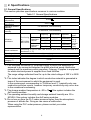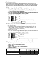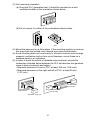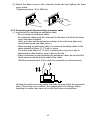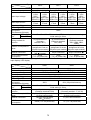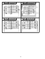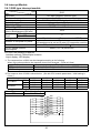
1
QCPU(Q mode) CPU Module User’s Manual (Hardware) Q00JCPU Q02CPU Q12PHCPU Q00CPU Q02HCPU Q25PHCPU Q01CPU Q06HCPU Q12HCPU Q25HCPU Thank you for buying the Mitsubishi programmable logic controller MELSEC-Q Series Prior to use, please read both this manual and detailed manual thoroughly and familiarize yourself with the product. MODEL QCPU(Q)-U(H/W)-E MODEL 13JL96 CODE IB(NA)-0800061-L(0305)MEE © 1999 MITSUBISHI ELECTRIC CORPORATION SAFETY PRECAUTIONS (Read these precautions before using) When using Mitsubishi equipment, thoroughly read this manual and the related manuals introduced in this manual. Also pay careful attention to safety and handle the module correctly. These SAFETY PRECAUTIONS classify the safety precautions into two categories: "DANGER" and "CAUTION". DANGER CAUTION Procedures which may lead to a dangerous condition and cause death or serious injury if not carried out correctly. Procedures which may lead to a dangerous condition and cause superficial to medium injury, or physical damage only, if not carried out correctly. Depending on circumstances, procedures indicated by CAUTION may also cause serious accidents. In any case, it is important to follow the directions for usage. Store this manual in a safe place so that you can take it out and read it whenever necessary. Always forward it to the end user. A-1 [DESIGN PRECAUTIONS] DANGER Install a safety circuit external to the PLC that keeps the entire system safe even when there are problems with the external power supply or the PLC module. Otherwise, trouble could result from erroneous output or erroneous operation. (1) Outside the PLC, construct mechanical damage preventing interlock circuits such as emergency stop, protective circuits, positioning upper and lower limits switches and interlocking forward/reverse operations. (2) When the PLC detects the following problems, it will stop calculation and turn off all output in the case of (a). In the case of (b), it will stop calculation and hold or turn off all output according to the parameter setting. Note that the AnS series module will turn off the output in either of cases (a) and (b). (a) The power supply module has over currentprotection equipment and over voltage protection equipment. (b) The CPU module self-diagnosis functions, such as the watch dog timer error, detect problems. In addition, all outputs will be turned on when there are problems that the CPU module cannot detect, such as in the I/O controller. Build a fail-safe circuit or provide a mechanism exterior to the PLC that will make sure the equipment operates safely at such times. For a failsafe circuit example, see "Loading and Installation" in this manual. (3) Output could be left on or off when there is trouble in the outputs module relay or transistor. So build an external monitoring circuit that will monitor any single outputs that could cause serious trouble. When overcurrent which exceeds the rating or caused by short-circuited load flows in the output module for a long time, it may cause smoke or fire. To prevent this, configure an external safety circuit, such as fuse. Build a circuit that turns on the external power supply when the PLC main module power is turned on. If the external power supply is turned on first, it could result in erroneous output or erroneous operation. A-2 [DESIGN PRECAUTIONS] DANGER When there are communication problems with the data link, refer to the corresponding data link manual for the operating status of each station. Not doing so could result in erroneous output or erroneous operation. When connecting a peripheral device to the CPU module or connecting a personal computer or the like to the intelligent function module to exercise control (data change) on the running PLC, configure up an interlock circuit in the sequence program to ensure that the whole system will always operate safely. Also before exercising other control (program change, operating status change (status control)) on the running PLC, read the manual carefully and fully confirm safety. Especially for the above control on the remote PLC from an external device, an immediate action may not be taken for PLC trouble due to a data communication fault. In addition to configuring up the interlock circuit in the sequence program, corrective and other actions to be taken as a system for the occurrence of a data communication fault should be predetermined between the external device and CPU module. CAUTION Do not bunch the control wires or communication cables with the main circuit or power wires, or install them close to each other. They should be installed 100 mm (3.94 inch) or more from each other. Not doing so could result in noise that would cause erroneous operation. When controlling items like lamp load, heater or solenoid valve using an output module, large current (approximately ten times greater than that present in normal circumstances) may flow when the output is turned OFF to ON. Take measures such as replacing the module with one having sufficient rated current. A-3 [INSTALLATION PRECAUTIONS] CAUTION Use the PLC in an environment that meets the general specifications contained in this manual. Using this PLC in an environment outside the range of the general specifications could result in electric shock, fire, erroneous operation, and damage to or deterioration of the product. Hold down the module mounting lever at the module bottom, and securely insert the module fixing latch into the fixing hole in the base unit. Incorrect mounting of the module can cause a malfunction, failure or drop. When using the PLC in the environment of much vibration, tighten the module with a screw. Tighten the screw in the specified torque range. Undertightening can cause a drop, short circuit or malfunction. Overtightening can cause a drop, short circuit or malfunction due to damage to the screw or module. When installing extension cables, be sure that the connectors of base unit are installed correctly. After installation, check them for looseness. Poor connections could cause an input or output failure. Securely mount the memory card into the memory card mounting connector. After mounting, check for lifting. Lifting can cause a malfunction due to a contact fault. Completely turn off the external power supply before mounting or removing the module. Not doing so could result in electric shock or damage to the product. Note that online module change can be made when the QnPHCPU is used. Note that there are restrictions on the modules that can be changed online and each module has a predetermined changing procedure. For details, refer to the section of online module change in the Process CPU User's Manual (Hardware Design,Maintenance and Inspection). Do not directly touch the module's conductive parts or electronic components. Touching the conductive parts could cause an operation failure or give damage to the module. A-4 [WIRING PRECAUTIONS] DANGER Completely turn off the external power supply when installing or placing wiring. Not completely turning off all power could result in electric shock or damage to the product. When turning on the power supply or operating the module after installation or wiring work, be sure that the module's terminal covers are correctly attached. Not attaching the terminal cover could result in electric shock. CAUTION Be sure to ground the FG terminals and LG terminals to the protective ground conductor. Not doing so could result in electric shock or erroneous operation. When wiring in the PLC, be sure that it is done correctly by checking the product's rated voltage and the terminal layout. Connecting a power supply that is different from the rating or incorrectly wiring the product could result in fire or damage. External connections shall be crimped or pressure welded with the specified tools, or correctly soldered. Imperfect connections could result in short circuit, fires, or erroneous operation. Tighten the terminal screws with the specified torque. If the terminal screws are loose, it could result in short circuits, fire, or erroneous operation. Tightening the terminal screws too far may cause damages to the screws and/or the module, resulting in fallout, short circuits, or malfunction. Be sure there are no foreign substances such as sawdust or wiring debris inside the module. Such debris could cause fires, damage, or erroneous operation. The module has an ingress prevention label on its top to prevent foreign matter, such as wire offcuts, from entering the module during wiring. Do not peel this label during wiring. Before starting system operation, be sure to peel this label because of heat dissipation. A-5 [STARTUP AND MAINTENANCE PRECAUTIONS] DANGER Do not touch the terminals while power is on. Doing so could cause shock or erroneous operation. Correctly connect the battery. Also, do not charge, disassemble, heat, place in fire, short circuit, or solder the battery. Mishandling of battery can cause overheating or cracks which could result in injury and fires. Switch all phases of the external power supply off when cleaning the module or retightening the terminal or module mounting screws. Not doing so could result in electric shock. Undertightening of terminal screws can cause a short circuit or malfunction. Overtightening of screws can cause damages to the screws and/or the module, resulting in fallout, short circuits, or malfunction. CAUTION The online operations conducted for the CPU module being operated, connecting the peripheral device (especially, when changing data or operation status), shall be conducted after the manual has been carefully read and a sufficient check of safety has been conducted. Operation mistakes could cause damage or problems with of the module. Do not disassemble or modify the modules. Doing so could cause trouble, erroneous operation, injury, or fire. Use any radio communication device such as a cellular phone or a PHS phone more than 25cm (9.85 inch) away from the PLC. Not doing so can cause a malfunction. Completely turn off the external power supply before loading or unloading the module. Not doing so could result in electric shock or damage to the product. Note that online module change can be made when the QnPHCPU is used. Note that there are restrictions on the modules that can be changed online and each module has a predetermined changing procedure. For details, refer to the section of online module change in the Process CPU User's Manual (Hardware Design,Maintenance and Inspection). Be sure not make a strong impact on the battery to be mounted into the module by dropping or similar careless action. This could break the battery, causing an internal battery liquid leakage. Do not use the battery which has been exposed to a strong impact, and dispose of it. Before touching the module, always touch grounded metal, etc. to discharge static electricity from the human body, etc. Not doing so can cause the module to fail or malfunction. [DISPOSAL PRECAUTIONS] CAUTION When disposing of this product, treat it as industrial waste. A-6 Revisions * The manual number is described at the lower right of the front cover. Print Date *Manual Number Revision Nov.,1999 IB(NA)-0800061-A First printing May.,2000 IB(NA)-0800061-B Q33B, Q63B, QX70, QX71, QX72, QY18A, QY22, QH42P and QX48Y57 added. Sep.,2000 IB(NA)-0800061-C QX28, QX40-S1, QI60 and Q63P added. Addition Section1.2, 4.5.5 Correction Section2.2, 6.1 Nov.,2000 IB(NA)-0800061-D QY70 and QY71 added. Correction Section5.4.1 Jan.,2001 IB(NA)-0800061-E Q62P, QY68A added. Correction Section4.1.2 May.,2001 IB(NA)-0800061-F Q00JCPU, Q00CPU, Q01CPU, Q52B and Q55B added. Partial addition Chapter 1, Table 4.2, Section 4.5, Section 4.5 changed to be Section 4.6. Sep.,2001 IB(NA)-0800061-G Q64P added. Partial addition Section 1.1, 3.1.5, 4.1.2, 4.1.4, 4.1.5, 4.3.1, 4.5.3, 4.6.4, 5.2.1 Mar.,2002 IB(NA)-0800061-H Q12PHCPU, Q25PHCPU added Correction Section 1.2, 2.2, 2.3, 4.3.1, 4.5.1, 4.6.1, 5.3.1, 5.3.2, 6.1 Jul.,2002 IB(NA)-0800061-I QX41-S1, QX42-S1 added Sep.,2002 IB(NA)-0800061-J Completely reviewed and revised. Q32SB, Q33SB, Q35SB, Q61SP added Jan.,2003 IB(NA)-0800061-K Correction Safety Precautions, About the Manuals, Section 2.2, 3.1.3, 3.1.5, 4.1.2, 4.4.1, 4.5.1 May.,2003 IB(NA)-0800061-L QX82, QX82-S1 added. Correction Section 2.2, 2.3, 4.1.2, 4.4.1, 4.4.2, 4.5.1, 4.5.2, 4.5.4, 4.6, 5.2.1 Japanese Manual Version IB (NA) -0800027-O This manual confers no industrial property rights or any rights of any other kind, nor does it confer any patent licenses. Mitsubishi electric Corporation cannot be held responsible for any problems involving industrial property rights which may occur as a result of using the contents noted in this manual. 1999 MITSUBISHI ELECTRIC CORPORATION A-7 CONTENTS 1. Overview....................................................................................................... 1 1.1 Included Parts......................................................................................... 1 1.2 Confirming the serial number and function version ................................. 3 2. Specifications ............................................................................................... 4 2.1 General Specifications ............................................................................ 4 2.2 Performance Specifications of CPU Modules.......................................... 5 2.3 Power supply module specifications ..................................................... 11 2.4 Specifications of Base Units.................................................................. 17 3. EMC and Low Voltage Directive ................................................................. 18 3.1 Requirements for conformance to EMC Directive ................................. 18 3.1.1 Standards applicable to the EMC Directive .................................. 19 3.1.2 Installation instructions for EMC Directive .................................... 20 3.1.3 Cables.......................................................................................... 21 3.1.4 Power supply module ................................................................... 25 3.1.5 When using QA1S6 B type base unit.......................................... 25 3.1.6 Others .......................................................................................... 29 3.2 Requirement to Conform to the Low Voltage Directive.......................... 30 3.2.1 Standard applied for MELSEC-Q series PLC ............................... 30 3.2.2 PLC selection............................................................................... 30 3.2.3 Power supply ............................................................................... 31 3.2.4 Control box................................................................................... 31 3.2.5 Grounding .................................................................................... 32 3.2.6 External wiring.............................................................................. 32 4. Mounting and Installation ............................................................................ 33 4.1 Module Installation ................................................................................ 33 4.1.1 Handling instructions.................................................................... 33 4.1.2 Instructions for mounting the base unit......................................... 35 4.1.3 Mounting and removing of module ............................................... 40 4.1.4 Setting the extension number of the extension base unit ............. 42 4.1.5 Connecting and disconnecting extension cable............................ 43 4.2 General Safety Requirements............................................................... 46 4.3 Power Supply Wiring............................................................................. 51 4.3.1 Precaution when connecting the uninterruptive power supply ...... 53 4.4 Part Names and Settings of Q00J/Q00/Q01CPU.................................. 54 4.4.1 Part names and settings............................................................... 54 4.4.2 Switch operation after writing program ......................................... 58 4.4.3 Reset operation............................................................................ 59 4.4.4 Latch clear operation.................................................................... 60 4.5 Part Names and Settings of Q02 (H) /Q06H/Q12H/Q25H/Q12PH/Q25PHCPU................................. 61 4.5.1 Part names and settings............................................................... 61 4.5.2 Switch operation after writing program ......................................... 64 4.5.3 Latch clear operation.................................................................... 64 4.5.4 Installing or removing the memory card when the power is on ..... 65 4.5.5 Executing automatic write to standard ROM. ............................... 66 A-8 4.6 Part Names of Power Supply Modules .................................................. 67 5. Specifications and Connections of I/O Modules .......................................... 70 5.1 Input Modules........................................................................................ 71 5.1.1 Specifications of input modules .................................................... 71 5.1.2 Connections of input modules....................................................... 77 5.2 Output Modules ..................................................................................... 80 5.2.1 Specifications of output modules .................................................. 80 5.2.2 Connections of output modules .................................................... 83 5.3 Input/output Composite Module............................................................. 87 5.3.1 QH42P type input/output compound module ................................ 87 5.3.2 QX48Y57 type input/output compound module............................. 90 5.4 Interrupt Module .................................................................................... 92 5.4.1 QI60 type interrupt module ........................................................... 92 5.5 Wiring of I/O Equipment ........................................................................ 93 6. Error Codes................................................................................................. 94 6.1 How to Read the Error Code ................................................................. 94 A-9 About the Manuals The following product manuals are available. Please use this table as a reference to request the appropriate manual as necessary. Basic Model QCPU (Q00JCPU, Q00CPU, Q01CPU) Detailed Manual Manual name Basic Model QCPU (Q Mode) User's Manual (Hardware Design, Maintenance and Inspection) This manual provides the specifications of the CPU modules, power supply modules, base units, extension cables and others. (Sold separately) Basic Model QCPU (Q Mode) User's Manual (Function Explanation, Program Fundamentals) This manual explains the functions, programming methods, devices and so on necessary to create programs with the Basic model QCPU (Q mode). (Sold separately) Manual No. (Model code) SH-080187 (13JR43) SH-080188 (13JR44) Relevant Manual Manual name QCPU (Q Mode)/QnACPU Programming Manual (Common Instructions) This manual explains how to use the sequence instructions, basic instructions, application instructions and similar instructions. (Sold separately) QCPU (Q mode) Programming Manual (MELSAP-L) Describes the system configuration, performance specifications, functions, programming, debugging, and error codes for MELSAP-L. (Sold separately) QCPU (Q mode)/QnACPU Programming Manual (PID Control Instructions) Describes the dedicated instructions for PID control. (Sold separately) Building Block I/O Module User's Manual This manual provides the specifications and external wiring of I/O modules. (Sold separately) QCPU (Q Mode)/Programming Manual (Structured Text) Describes the programming method of the structured text language. A-10 Manual No. (Model code) SH-080039 (13JF58) SH-080076 (13JF61) SH-080040 (13JF59) SH-080042 (13JL99) SH-080366E (13JF68) High Performance Model QCPU (Q02 (H) CPU, Q06HCPU, Q12HCPU, Q25HCPU) Detailed Manual Manual name High Performance Model QCPU (Q Mode) User's Manual (Hardware Design, Maintenance and Inspection) This manual provides the specifications of the CPU modules, power supply modules, base units, extension cables, memory cards and others. (Sold separately) High Performance Model QCPU (Q Mode) User's Manual (Function Explanation, Program Fundamentals) This manual explains the functions, programming methods, devices and so on necessary to create programs with the High Performance model QCPU (Q mode). (Sold separately) Manual No. (Model code) SH-080037 (13JL97) SH-080038 (13JL98) Relevant Manual Manual name QCPU (Q Mode)/QnACPU Programming Manual (Common Instructions) This manual explains how to use the sequence instructions, basic instructions, application instructions and similar instructions. (Sold separately) QCPU (Q Mode)/QnACPU Programming Manual (PID Control) This manual explains the dedicated instructions used to exercise PID control. (Sold separately) QCPU (Q Mode)/QnACPU Programming Manual (SFC) This manual explains the system configuration, performance specifications, functions, programming, debugging, error codes and others of MELSAP3. (Sold separately) QCPU (Q Mode)/QnACPU Programming Manual (MELSAP-L) This manual explains the programming methods, specifications, functions, and so on that are necessary to create the MELSAP-L type SFC programs. (Sold separately) Building Block I/O Module User's Manual This manual provides the specifications and external wiring of I/O modules. (Sold separately) QCPU (Q Mode)/Programming Manual (Structured Text) Describes the programming method of the structured text language. A-11 Manual No. (Model code) SH-080039 (13JF58) SH-080040 (13JF59) SH-080041 (13JF60) SH-080076 (13JF61) SH-080042 (13JL99) SH-080366E (13JF68) Process CPU (Q12PHCPU, Q25PHCPU) Detailed Manual Manual name Process CPU User's Manual (Hardware Design, Maintenance and Inspection) This manual provides the specifications of the CPU modules, power supply modules, base units, extension cables, memory cards and others. (Sold separately) Process CPU User's Manual (Function Explanation, Program Fundamentals) This manual explains the functions, programming methods, devices and so on necessary to create programs with the Process CPU (Sold separately) Manual No. (Model code) SH-080314E (13JR55) SH-080315E (13JR56) Relevant Manual Manual name QCPU (Q Mode)/QnACPU Programming Manual (Common Instructions) This manual explains how to use the sequence instructions, basic instructions and application instructions. (Sold separately) QnPHCPU Programming Manual (Process Control Instructions) This manual explains the programming procedures, device names, and other items necessary to implement PID control using process control instructions. (Sold separately) QCPU (Q Mode)/QnACPU Programming Manual (SFC) This manual explains the system configuration, performance specifications, functions, programming, debugging, error codes and others of MELSAP3. (Sold separately) QCPU (Q Mode)/QnACPU Programming Manual (MELSAP-L) This manual explains the programming methods, specifications, functions, and so on that are necessary to create the MELSAP-L type SFC programs. (Sold separately) Building Block I/O Module User's Manual This manual privides the specifications and external wiring of I/O modules. (Sold separately) QCPU (Q Mode)/Programming Manual (Structured Text) Describes the programming method of the structured text language. A-12 Manual No. (Model code) SH-080039 (13JF58) SH-080316E (13JF67) SH-080041 (13JF60) SH-080076 (13JF61) SH-080042 (13JL99) SH-080366E (13JF68) 1. Overview This manual provides the performance specifications, loading and installation, and part names and settings of the MELSEC-Q series CPU modules, the specifications and connection of the I/O modules, and how to read error codes. The CPU type is abbreviated to the QCPU when description is common to the MELSEC-Q series CPU modules. The usable extension base units and the number of extension bases vary with the CPU module used. The following table indicates the CPU module types described in this manual and differences between them. CPU Module Type Q00JCPU Q00CPU Q01CPU Q02 (H) CPU Q06HCPU Q12HCPU Q25HCPU Q12PHCPU Q25PHCPU Extension Base Q5B Q6B QA1SB Usable Usable *1 Usable Usable *1 Unusable Number of Extension Bases 2 Unusable 4 24 Necessary Usable *1 Usable *1 Usable *1 7 64 Necessary *2 Usable Usable Unusable 7 64 Main Base Unnecessary Necessary Number of mountable Modules 16 *1: Extension base unit cannot be connected when the slim type main base unit (Q32SB, Q33SB, Q35SB) is used. *2: Q12PHCPU and Q25PHCPU are not compatible with the slim type main base unit (Q32SB, Q33SB, Q35SB). 1.1 Included Parts The following tables list the parts included with the corresponding modules. (1) CPU module (a) Q00JCPU Product Name CPU module Battery Base unit mounting screw This manual Type Q00JCPU Q6BAT M4 14 screw —— Quantity 1 1 4 1 (b) Other than Q00JCPU Product Name CPU module Battery Type Q00CPU Q01CPU Q02CPU Q02HCPU Q06HCPU Q12HCPU Q25HCPU Q12PHCPU Q25PHCPU Q6BAT 1 Quantity 1 1 (2) Main base unit for Q series modules Product Name Main base unit Base unit mounting screw This manual Type Q33B Q35B Q38B Q312B M4 14 screw —— Quantity 1 4 1 (3) Slim type main base unit for Q series module Product Name Slim type main base unit Base unit mounting screw This manual Type Q32SB Q33SB Q35SB M4 12 screw —— Quantity 1 4 1 (4) Extension base unit for Q series modules Product Name Extension base unit Base unit mounting screw Type Q52B Q55B Q63B Q65B Q68B Q612B M4 14 screw Quantity 1 4 (5) Extension base unit for AnS series modules (Only Q02CPU, Q02HCPU, Q06HCPU, Q12HCPU or Q25HCPU is usable) Product Name Extension base unit Base unit mounting screw Type QA1S65B QA1S68B M5 screw Quantity 1 4 (6) Power supply module Product Name Power supply module Type Q61P-A1 Q61P-A2 Q62P Q63P Q64P Q61SP A1S61PN A1S62PN A1S63P Quantity 1 2 1.2 Confirming the serial number and function version The QCPU serial No. and function version can be confirmed on the rating nameplate and GX Developer's system monitor. (1) Confirmation on the rating nameplate MELSEC-Q MODEL Function version SERIAL 05032 0000000000 C 80M1 IND. CONT. EQ. MADE IN JAPAN (2) Confirmation on the system monitor The QCPU serial No. and function version can be confirmed with Product Information List on the GX Developer's system monitor.* The intelligent function module's serial No. and function version can also be confirmed. Serial number Function version * : The version of compatible GX Developer varies depending on the CPU module. Type Q00JCPU Q00CPU Q01CPU Q02CPU Q02HCPU Q06HCPU Q12HCPU Q25HCPU Q12PHCPU Q25PHCPU Version of Compatible GX Developer GX Developer Version 7 or later GX Developer Version 6 or later GX Developer Version 7.10L or later 3 2. Specifications 2.1 General Specifications This section provides specifications common to various modules. Table 2.1 General Specifications Item Operating ambient temperature Storage ambient temperature Operating ambient humidity Storage ambient humidity Specifications 0 to 55 -25 to 75 *3 5 to 95%RH*4, non-condensing 5 to 95%RH*4, non-condensing Frequency Acceleration Amplitude 0.075mm (0.003inch) Vibration 9.8m/s2 ——— 57 to 150Hz resistance 0.035mm 10 to 57Hz ——— (0.001inch) 2 4.9m/s ——— 57 to 150Hz 2 Conforming to JIS B 3502, IEC 61131-2 (147 m/s , 3 times in Shock resistance directions X, Y, Z) Operating ambience No corrosive gases Operating altitude 2000m (6562ft.) max. Installation position Inside control panel Overvoltage II max. category *1 Pollution level *2 2 max. Conforming to JIS B 3502, IEC 61131-2 Under intermittent vibration Under continuous vibration 10 to 57Hz ——— Sweep count 10 times each in X, Y, Z directions (for 80 minch) each of 3 *1: This indicates the section of the power supply to which the equipment is assumed to be connected between the public electrical power distribution network and the machinery within premises. Category II applies to equipment for which electrical power is supplied from fixed facilities. The surge voltage withstand level for up to the rated voltage of 300 V is 2500 V. *2: This index indicates the degree to which conductive material is generated in terms of the environment in which the equipment is used. In the environment corresponding to “Pollution level 2”, basically only nonconductive pollution occurs, however temporary conductivity may occur due to the occasional condensing. *3: The storage ambient temperature is -20 to 75 if the system includes the AnS series modules. *4: The operating ambient humidity and storage ambient humidity are 10 to 90%RH if the system includes the AnS series modules. *5: Do not use or store the PLC under pressure higher than the atmospheric pressure of altitude 0m. Doing so can cause a malfunction. When using the PLC under pressure, please contact your sales representative. 4 2.2 Performance Specifications of CPU Modules This section provides the performance specifications of the CPU modules. Table 2.2 Q00JCPU, Q00CPU, Q01CPU Performance Specifications Control method Type Q00JCPU Q00CPU Q01CPU Repeated operation using stored program I/O control mode Refresh mode Item Remarks —— Direct I/O is available by direct I/O specification (DX , DY ) Relay symbol language, logic symbolic MELSAP3 (SFC), MELSAP-L function block, —— structured text LD X0 0.20 s 0.16 s 0.10 s Processing speed —— (sequence instruction) MOV D0 D1 0.70 s 0.56 s 0.35 s Total number of instructions 318 327 —— (except instructions dedicated to intelligent function module) Constant scan (Function that 1 to 2000ms Parameter setting uniforms scan time) (can be specified in 1ms increments) Program capacity *1 8k steps 8k steps 14k steps —— Program memory 58kbyte 94kbyte —— (Drive 0) Standard RAM None 128kbyte*2 —— (Drive 3) Memory capacity Standard ROM 58kbyte 94kbyte —— (Drive 4) CPU shared None 512 words —— memory Program Program 2 programs (one SFC and one ladder) —— execution management Number of standard ROM write Max. 100 thousand times —— times Number of points Number of I/O device points 2048 points (X/Y0 to 7FF) available in programs Number of points 256 points 1024 points accessible to Number of occupied I/O points (X/Y0 to FF) (X/Y0 to 3FF) actual I/O modules Number of extension bases 2 4 —— Number of loadable modules 16 24 —— Year, month, day, hour, minute, second, day of week (Automatic leap year judgment) Accuracy Clock function —— -3.2 to +5.27s (TYP. +1.98s)/d at 0 -2.57 to +5.27s (TYP. +2.22s)/d at 25 -11.68 to +3.65s (TYP. -2.64s)/d at 55 Allowable momentaly power failure Within 20ms depending on power —— period (100V AC or more) supply module 5V DC internal current consumption 0.22A *5 0.25A 0.27A —— H 98mm (3.86inch) 98mm (3.86inch) —— 245mm W 27.4mm (1.08inch) —— External dimensions (9.65inch) *5 98mm D 89.3mm (3.52inch) —— (3.86inch) Weight 0.66kg *5 0.13kg —— Programming language (Language dedicated to sequence control) 5 *1: The maximum number of sequence steps that can be executed by the CPU module is as indicated by the following expression.(Program capacity) - (file header size (default: 34 steps) Refer to the following manual for details of the program capacity and file. • Basic Model QCPU (Q Mode) User's Manual (Function Explanation, Program Fundamentals) *2: 64K bytes for function version A. *3: Memory added to function version B. The CPU shared memory is not latched. Powering on the PLC or resetting the CPU module clears the CPU shared memory. *4: Added to function version B. *5: Value including those of the CPU module, base unit and power supply module. 6 Table 2.3 Q02(H)CPU, Q06HCPU, Q12HCPU, Q25HCPU Performance Specifications Control method Type Q02 Q02H Q06H Q12H Q25H CPU CPU CPU CPU CPU Repeated operation using stored program I/O control mode Refresh mode Item Programming language (Language dedicated to sequence control Relay symbol language, logic symbolic language, MELSAP3 (SFC), MELSAP-L and function block, structured text LD X0 0.079 s Processing speed (sequence instruction) MOV D0 D1 0.237 s Total number of instructions Constant scan (Function that uniforms scan time) Program Program memory capacity (Drive 0) *2 Memory card (RAM) (Drive 1) Memory card (ROM) Memory (Drive 2) capacity Standard RAM (Drive 3) Standard ROM (Drive 4) Max. number of files stored CPU shared memory*4 Program memory Memory card (RAM) Memory card Flash card (ROM) ATA card Standard ROM Number of standard ROM write times 0.102 s —— 60k step 124k step 252k step 2 28 —— —— Capacity of the memory card (max. 2Mbyte) Capacity of the memory card loaded (Flash card: max. 4Mbyte, ATA card: max. 32Mbyte) 64kbyte 128kbyte *5 256kbyte *3 112 240 496 1008 kbyte kbyte kbyte kbyte 8kbyte 28 60 124 252 *1 256 288 512 Standard RAM —— Direct I/O is available by direct I/O specification (DX , DY ) 0.034 s 381 (except instructions dedicated to intelligent function module) 0.5 to 2000 ms (can be specified in 0.5ms increments) 28k step Remarks 60 124 Max. 100 thousand times 252 —— Parameter setting —— —— —— —— —— —— —— —— —— —— Only one file each for file register and local device —— —— *1: The CPU module can execute 124 files. It cannot execute 125 or more files. *2: The maximum number of sequence steps (for one program) for which the parameters are stored in another drive and executed with the CPU module can be calculated with the following expression. (Program size) - (File header size (default : 34 steps)) Refer to the High Performance model QCPU (Q Mode) User's Manual (Function Explanation, Program Fundamentals) for details on the program size and file. 7 Item Q02 CPU Q02H CPU Type Q06H CPU Q12H CPU Q25H CPU Number of I/O device points 8192 points (X/Y0 to 1FFF) Number of occupied I/O points 4096 points (X/Y0 to FFF) Number of extension bases Number of mountable modules 7 64 Year, month, day, hour, minute, second, day of week (Automatic leap year judgment) Accuracy -3.18 to +5.25s (TYP.+2.12s)/d at 0 -3.93 to +5.25s (TYP.+1.90s)/d at 25 -14.69 to +3.53s (TYP.-3.67s)/d at 55 Clock function Allowable momentary power failure period 5V DC internal current consumption External dimensions Weight Depends on power supply module. 0.60A H W D 0.64A 98mm (3.86inch) 27.4mm (1.08inch) 89.3mm (3.52inch) 0.20kg Remarks Number of points available in programs Number of points accessible to actual I/O modules —— —— —— —— —— —— —— —— —— *3: The memory capacity of the Q12HCPU or Q25HCPU whose serial No.'s first five digits are "02091" or earlier is 64kbyte. (See to section 1.2 for the way to check the serial No.) *4: Memory added to the function version B. The CPU shared memory is not latched. The CPU shared memory is cleared when the PLC is powered on or the CPU module is reset. *5: The memory capacity of the Q02HCPU or Q06HCPU whose serial No.'s first five digits are "04011" or earlier is 64kbyte. (See to Section 1.2 for the way to check the serial No.) 8 Table 2.4 Q12PHCPU, Q25PHCPU Performance Specifications Item Control method Type Q12PHCPU Q25PHCPU Repeated operation using stored program I/O control mode Programming language (Language dedicated to sequence control) Refresh mode Relay symbol language, logic symbolic language, MELSAP3 (SFC), MELSAP-L, and function block, structured text LD X0 Processing speed (sequence instruction) MOV D0 D1 Total number of instructions Constant scan (Function that uniforms scan time) Program Program memory capacity (Drive 0) *2 Memory card (RAM) (Drive 1) Memory capacity Max. number of files stored Memory card (ROM) (Drive 2) Standard RAM (Drive 3) Standard ROM (Drive 4) CPU shared memory*3 Program memory Memory card (RAM) Memory Flash card card ATA card (ROM) —— Direct I/O is available by direct I/O specification (DX , DY ) —— 0.034 s —— 0.102 s —— 422 (except instructions dedicated to intelligent function module) 0.5 to 2000 ms (can be specified in 0.5ms increments) 124k step 252k step —— Parameter setting —— Capacity of mounted memory card (max. 2Mbyte) Capacity of mounted memory card (Flash card: max. 4Mbyte, ATA card: max. 32Mbyte) 256kbyte 496kbyte 1008kbyte 8kbyte 124 252 *1 256 288 —— —— —— —— —— —— 512 —— Standard RAM Standard ROM Number of standard ROM write times Remarks 2 124 252 Max. 100 thousand times —— —— Only one file each for file register and local device —— —— *1: The CPU module can execute 124 files. It cannot execute 125 or more files. *2: The maximum number of sequence steps (for one program) for which the parameters are stored in another drive and executed with the CPU module can be calculated with the following expression. (Program size) - (File header size (default : 34 steps)) Refer to the Process CPU User's Manual (Function Explanation, Program Fundamentals) for details on the program size and file. *3: The CPU shared memory is not latched. The CPU shared memory is cleared when the PLC is powered on or the CPU module is reset. 9 Type Item Q12PHCPU Q25PHCPU Number of I/O device points 8192 points (X/Y0 to 1FFF) Number of occupied I/O points 4096 points (X/Y0 to FFF) Number of extension bases Number of mountable modules 7 64 Year, month, day, hour, minute, second, day of week (Automatic leap year judgment) Accuracy -3.18 to +5.25s (TYP.+2.12s)/d at 0 -3.93 to +5.25s (TYP.+1.90s)/d at 25 -14.69 to +3.53s (TYP.-3.67s)/d at 55 Clock function Allowable momentaly power failure period 5V DC internal current consumption External dimensions Weight H W D Remarks Number of points available in programs Number of points accessible to actual I/O modules —— —— —— Depends on power supply module. —— 0.64A —— 98mm (3.86inch) 27.4mm (1.08inch) 89.3mm (3.52inch) 0.20kg —— —— —— —— 10 2.3 Power supply module specifications This section provides the specifications of the power supply modules. Table 2.5 Q61P-A1/A2, Q62P, Q63P Performance Specification List Performance Specifications Q61P-A2 Q62P Q63P Base mounting position Power supply module mounting slot Applicable base unit Q3B, Q6B 100 to 120V AC (- 200 to 240V AC 100 to 240V AC 24V DC Input power supply 15%/+10%) (-15%/+10%) (-15%/+10%) (-35%/+30%) (85V to 132V AC) (170 to 264V AC) (85V to 264V AC) (15.6 to 31.2V DC) Input frequency 50/60Hz 5% —— Input voltage distortion factor Within 5% (See section 4.3.1) —— Max. input apparent power 105VA —— Max. input power —— 45W Inrush current 20A within 8ms 100A within 1ms 5V DC 6A 3A 6A Rated output current 24V DC —— 0.6A —— 24V DC External output voltage —— —— (-10%/+10%) 6.6A or more 3.3A or more 6.6A or more Overcurrent 5V DC protection*1 24V DC —— 0.66A or more —— 5.5 to 6.5V Overvoltage 5V DC protection*2 24V DC —— Efficiency 70% or more 65% or more 70% or more Allowable momentary power Within 10ms Within 20ms failure period*3 (at 24V DC input) Across inputs/LG and outputs/FG 500V AC across Dielectric withstand voltage 2,830V AC rms/3 cycles (2,000 m (6562 ft.)) primary and 5V DC Across inputs and outputs (LG and FG separated), 10M or more by across inputs and LG/FG, across outputs and Insulation resistance insulation FG/LG 10M or more by insulation resistance resistance tester tester By noise simulator of 500Vp-p noise • By noise simulator of 1,500Vp-p noise voltage, voltage, 1 s noise Noise durability 1 s noise width and 25 to 60Hz noise frequency width and 25 to • Noise voltage IEC61000-4-4, 2kV 60Hz noise frequency Operation display LED display (lit at 5V DC output) Fuse Built-in (Unchangeable by user) ERR contact (contact switched off (opened: normally closed contact) at Application an error stop of CPU module), for CPU module operating status output Rated switching 24V DC, 0.5A voltage, current Minimum switching 5V DC, 1mA Contact load output Response time OFF to ON: 10ms max. ON to OFF: 12ms max. section Mechanical: More than 20 million times Life Electrical : More than 100 thousand times at rated switching voltage, current Surge suppressor None Fuse None Terminal screw size M3.5 7 Applicable wire size 0.75 to 2mm2 Applicable solderless terminal RAV1.25-3.5, RAV2-3.5 Applicable tightening torque 66 to 89N•cm H 98mm (3.86inch) External W 55.2mm (2.17inch) dimensions D 90mm (3.55inch) Weight 0.31kg 0.39kg 0.33kg Item Q61P-A1 11 Table 2.6 Q64P Performance Specifications Item Base mounting position Applicable base unit Input power supply Input frequency Input voltage distortion factor Max. input apparent power Inrush current Rated output 5V DC current 24V DC Overcurrent 5V DC protection*1 24V DC Overvoltage 5V DC protection*2 24V DC Efficiency Allowable momentary power failure period*3 Dielectric withstand voltage Insulation resistance Noise durability Operation display Fuse Application Rated switching voltage, current Minimum Contact switching load output Response time section Life Surge suppressor Fuse Terminal screw size Applicable wire size Applicable solderless terminal Applicable tightening torque H External dimensions W D Weight Performance Specifications Q64P Power supply module mounting slot Q3B, Q6B 100 to 120V AC/200 to 240V AC (-15%/+10%) (85V to 132V AC/170 to 264V AC) 50/60Hz 5% Within 5% (See section 4.3.1) 160VA 20A within 8ms 8.5A —— 9.9A or more —— 5.5 to 6.5V —— 70% or more Within 20ms Across inputs/LG and outputs/FG 2,830V AC rms/3 cycles (2,000 m (6562 ft.)) Across inputs and outputs (LG and FG separated), across inputs and LG/FG, across outputs and FG/LG 10M or more by insulation resistance tester • By noise simulator of 1,500Vp-p noise voltage, 1 s noise width and 25 to 60Hz noise frequency • Noise voltage IEC61000-4-4, 2kV LED display (lit at 5V DC output) Built-in (Unchangeable by user) ERR contact (contact switched off (opened: normally closed contact) at an error stop of CPU module), for CPU module operating status output 24V DC, 0.5A 5V DC, 1mA OFF to ON: 10ms max. ON to OFF: 12ms max. Mechanical : More than 20 million times Electrical : More than 100 thousand times at rated switching voltage, current None None M3.5 7 0.75 to 2mm2 RAV1.25-3.5, RAV2-3.5 66 to 89N•cm 98mm (3.86inch) 55.2mm (2.17inch) 115mm (4.53inch) 0.40kg 12 Table 2.7 Q61SP Performance/Specifications Item Base mounting position Applicable base unit Input power supply Input frequency Input voltage distortion rate Maximum input apparent power Inrush current 5V DC Rated input current 24V DC 5V DC Overcurrent protection *1 24V DC 5V DC Overvoltage protection *2 24V DC Efficiency Allowable momentary power failure period Dielectric withstand voltage Insulation resistance *3 Noise durability Operation display Fuse Application Contact output Rated switching voltage, current Minimum switching load Response time Life Surge suppresser Fuse Terminal screw size Applicable wire size Applicable solderless terminal Applicable tightening torque H External dimensions W D Weight Performance/Specifications Q61SP Slim type power supply module mounting slot Q3 SB 100 to 240V AC +10% -15% (85 to 264V AC) 50/60Hz +-5% Within 5% (See section 4.3.1) 40VA Within 20A for 8 sec. 2.0A 2.2A or more 5.5 to 6.5V 70% or more Within 20ms (AC 100 V or more) Across inputs/LG and outputs/FG 2,830V AC crms/3 cycles (2,000m) Across inputs and outputs (LG and FG are separated), across inputs and LG/FG, across outputs and FG/LG, 10M• or more by 500V DC insulation resistance tester • By noise simulator of 1500Vp-p noise voltage, 1•s noise width and 25 to 60HZ noise frequency • Noise voltage IEC61000-4-4, 2kV LED display (lit at 5V DC output) Built-in (Unchangeable by user) ERR contact (contact switched off (opened: B-contact) at error stop of CPU module) for CPU module operating status output 24V DC, 0.5A 5V DC, 1mA OFF to ON: 10ms max. ON to OFF: 12ms max. Mechanic: More than 20 million times Electrical: More than 100 thousand times at rated switching voltage, current None None M3.5 7 0.75 to 2mm2 RAV1.25-3.5, RAV2-3.5 66 to 89N•cm 98mm (3.86inch) 55.2mm (2.17inch) 104mm (4.09inch) 0.18kg 13 Table 2.8 Q00JCPU (Power Supply Section) Performance Specifications Item Input power supply Input frequency Input voltage distortion factor Max. input apparent power Inrush current Rated output DC5V current DC24V DC5V Overcurrent protection*1 DC24V Overvoltage DC5V protection*2 DC24V Efficiency Allowable instantaneous power failure time*3 Dielectric withstand voltage Insulation resistance Noise durability Operation display Fuse Contact output section Terminal screw size Applicable wire size Applicable solderless terminal Applicable tightening torque External dimensions Weight Performance Specifications Q00JCPU (power supply section) 100 to 240V AC (-15%/+10%) (85 to 264V AC) 50/60Hz 5% Within 5% (See section 4.3.1) 105VA 40A within 8ms 3A —— 3.3A or more —— 5.5 to 6.5V —— 65% or more Within 20ms (100V AC or more) Across inputs/LG and outputs/FG 2,830V AC rms/3 cycles (altitude 2,000 m (6,562 ft.)) Across inputs and outputs (LG and FG separated), across inputs and LG/FG, across outputs and FG/LG 10M or more by 500V DC insulation resistance tester • By noise simulator of 1,500Vp-p noise voltage, 1 s noise width and 25 to 60Hz noise frequency • Noise voltage IEC61000-4-4, 2kV LED display (lit at 5V DC output) Built-in (Unchangeable by user) None M3.5 7 0.75 to 2mm2 RAV1.25-3.5, RAV2-3.5 66 to 89N•cm Refer to Table 2.2 14 Table 2.9 A1S61PN, A1S62PN, A1S63P Performance Specifications Item Base mounting position Applicable base unit Input power supply Input frequency Input voltage distortion factor Max. input apparent power Max. input power Inrush current Rated output 5V DC current 24V DC External output voltage Overcurrent 5V DC protection*1 24V DC Overvoltage 5V DC protection*2 24V DC Efficiency Allowable momentary power failure period*3 Dielectric withstand voltage Insulation resistance Noise durability Operation display Fuse Contact output section Terminal screw size Applicable wire size Applicable solderless terminal Applicable tightening torque H External W dimensions D Weight Performance Specifications A1S61PN A1S62PN A1S63P Power supply module mounting slot QA1S65B, QA1S68B 24V DC 100 to 240V AC (-15%/+10%) (-35%/+30%) (85 to 264V AC) (15.6 to 31.2V DC) 50/60Hz 5% —— Within 5% (See section 4.3.1) 105VA —— 20A within 8ms 5A —— —— 5.5A or more —— 3A 0.6A 24V DC (-10%/+10%) 3.3A or more 0.66A or more 5.5 to 6.5V —— 65% or more Within 20ms Across inputs/LG and outputs/FG 2,830V AC rms/3 cycles (2,000 m (6562 ft.)) Across inputs and outputs (LG and FG separated), across inputs and LG/FG, across outputs and FG/LG 10M or more by insulation resistance tester —— 41W 81A within 1ms 5A —— —— 5.5A or more —— Within 10ms (at 24V DC input) 500V AC across primary and 5V DC 5M or more by insulation resistance tester By noise simulator of 500Vp-p noise voltage, 1 s noise width and 25 to 60Hz noise frequency LED display (lit at 5V DC output) Built-in (Unchangeable by user) None M3.5 7 0.75 to 2mm2 • By noise simulator of 1,500Vp-p noise voltage, 1 s noise width and 25 to 60Hz noise frequency • Noise voltage IEC61000-4-4, 2kV RAV1.25-3.5, RAV2-3.5 66 to 89N•cm 130mm (5.12inch) 55mm (2.17inch) 93.6 (3.69inch) 0.60kg 15 0.50kg POINT *1 : Overcurrent protection The overcurrent protection device shuts off the 5V, 24V DC circuit and stops the system if the current flowing in the circuit exceeds the specified value. If this device is activated, switch the input power supply off and eliminate the cause such as insufficient current capacity or short. Then, a few minutes later, switch it on to restart the system. The initial start for the system takes place when the current value becomes normal. *2 : Overvoltage protection The overvoltage protection device shuts off the 5V DC circuit and stops the system if a voltage of 5.5 to 6.5V DC is applied to the circuit. When this device is activated, the power supply module LED is switched OFF. If this happens, switch the input power OFF, then a few minutes later ON. This causes the initial start for the system to take place. The power supply module must be changed if the system is not booted and the LED remains OFF. *3 : Allowable momentary power failure period (1) For AC input power supply y An instantaneous power failure lasting less than 20ms will cause AC down to be detected, but operation will continue. y An instantaneous power failure lasting more than 20ms may cause the operation to continue or initial start to take place depending on the power supply load. Furthermore, by using the same AC power supply for the AC input module and the power supply module, it is possible to prevent the sensor, to which the AC input module is connected, from turning OFF when it is ON when the power is turned OFF. However, if only the AC input module is connected to the AC line, which is connected to the power suppludetection of the AC down for the power supply module may be delayed by the capacitor in the AC input module. Thus, connect a load of approx. 30mA per QX10 unit to the AC line. (2) For DC input power supply y An instantaneous power failure lasting less than 10ms (*4) will cause 24V DC down to be detected, but operation will continue. y An instantaneous power failure lasting more than 10ms (*4) may cause the operation to continue or initial start to take place depending on the power supply load. (*4: This is for a 24V DC input. This is 10ms or less for 24V DC or less.) 16 2.4 Specifications of Base Units (1) Main base units Item Type Number of mountable I/O modules Applicable modules 5V DC internal Current consumption Weight H External dimensions W D Q00JCPU Q33B Q35B Q38B Q312B 2 3 5 8 12 0.114A 0.121A Q series modules 0.220A 0.105A 0.66kg 0.21kg 0.110A 0.25kg 0.35kg 98mm (3.86inch) 189mm 245mm 328mm (7.44inch) (9.65inch) (12.92inch) 245mm (9.65inch) 97mm (3.82inch) 0.45kg 439mm (17.30inch) 44.1mm (1.74inch) (2) Slim type main base units Item Type Number of mountable I/O modules Applicable modules 5V DC internal Current consumption Weight H External W dimensions D Q32SB Q33SB Q35SB 2 3 5 Q series modules 0.086A 0.086A 0.091A 0.12kg 0.15kg 98mm (3.86inch) 142mm (5.59inch) 18.5mm (0.73inch) 0.21kg 114mm (4.49inch) 197.5mm (7.78inch) (3) Extension base units Item Q52B Q55B Q63B Q65B Q68B Q612B Type Number of mountable 2 5 3 5 8 12 I/O modules Applicable modules Q series modules 5V DC internal Current 0.080A 0.100A 0.105A 0.110A 0.114A 0.121A consumption Weight 0.14kg 0.23kg 0.23kg 0.25kg 0.35kg 0.45kg H 98mm (3.86inch) External 106mm 189mm 189mm 245mm 328mm 439mm W dimensions (4.17inch) (7.44inch) (7.44inch) (9.65inch) (12.92inch) (17.30inch) D 44.1mm (1.74inch) Item Type Number of mountable I/O modules Applicable modules 5V DC internal current consumption Weight H External W dimensions D QA1S65B QA1S68B 5 8 AnS series modules 0.117A 0.75kg 0.118A 1.00kg 130mm (5.12inch) 315mm (12.41inch) 420mm (16.55inch) 51.2mm (2.02inch) 17 3. EMC and Low Voltage Directive For the products sold in European countries, the conformance to the EMC Directive, which is one of the European Directives, has been a legal obligation since 1996. Also, conformance to the Low Voltage Directive, another European Directives, has been a legal obligation since 1997. Manufacturers who recognize their products must conform to the EMC and Low Voltage Directive are required to declare that their products conform to these Directives and put a "CE mark" on their products. 3.1 Requirements for conformance to EMC Directive The EMC Directive specifies that products placed on the market must "be so constructed that they do not cause excessive electromagnetic interference (emissions) and are not unduly affected by electromagnetic interference (immunity) ". The applicable products are requested to meet these requirements. The sections 3.1.1 through 3.1.6 summarize the precautions on conformance to the EMC Directive of the machinery constructed using the MELSEC-Q series PLCs. The details of these precautions has been prepared based on the control requirements and the applicable standards . However, we will not assure that the overall machinery manufactured according to these details conforms to the above-mentioned directives. The method of conformance to the EMC Directive and the judgment on whether or not the machinery conforms to the EMC Directive must be determined finally by the manufacturer of the machinery. 18 3.1.1 Standards applicable to the EMC Directive The standards applicable to the EMC Directive are listed below. Specification Test item EN55011 Radiated noise *2 EN50081-2 : 1995 EN55011 Conducted noise EN61000-4-2 Electrostatic immunity *2 EN61131-2 : 1996 EN61000-4-4 Fast transient burst noise *2 EN61000-4-3 Radiated field AM modulation *2 EN61000-4-12 Damped oscillatory wave immunity Test details Standard value 30M-230MHz QP : 30dB V/m Electromagnetic (30 m in measurement range) *1 emissions from the 230M-1000MHz QP : 37 dB product are V/m measured. (30 m in measurement range) Electromagnetic 150k-500kHz QP: 79 dB, emissions from the Mean: 66 dB *1 product to the power 500k-30MHz QP: 73 dB, line is measured. Mean: 60 dB Immunity test in which static electricity is applied 15kV Aerial discharge to the cabinet of the equipment. Immunity test in Power line: 2kV which burst noise is Digital I/O (24V or higher): 1kV applied to the power (Digital I/O (24V or less)) > 250V line and signal lines. (Analog I/O, signal lines) > 250V Immunity test in which field is 10V/m, 26-1000MHz, irradiated to the 80%AM modulation@1kHz product. Immunity test in which a damped Power line: 1kV oscillatory wave is Digital I/O (24V or higher): 1kV superimposed on the power line. *1: QP : Quasi-peak value, Mean : Average value *2: The PLC is an open type device (device installed to another device) and must be installed in a conductive control panel. The tests for the corresponding items were performed while the PLC was installed inside a control panel. 19 3.1.2 Installation instructions for EMC Directive The PLC is open equipment and must be installed within a control cabinet for use. This not only ensures safety but also ensures effective shielding of PLCgenerated electromagnetic noise. (1) Control cabinet (a) Use a conductive control cabinet. (b) When attaching the control cabinet's top plate or base plate, mask painting and weld so that good surface contact can be made between the cabinet and plate. (c) To ensure good electrical contact with the control cabinet, mask the paint on the installation bolts of the inner plate in the control cabinet so that contact between surfaces can be ensured over the widest possible area. (d) Earth the control cabinet with a thick wire so that a low impedance connection to ground can be ensured even at high frequencies. (e) Holes made in the control cabinet must be 10 cm (3.94 inch) diameter or less. If the holes are 10 cm (3.94 inch) or larger, radio frequency noise may be emitted. In addition, because radio waves leak through a clearance between the control panel door and the main unit, reduce the clearance as much as practicable. The leakage of radio waves can be suppressed by the direct application of an EMI gasket on the paint surface. Our tests have been carried out on a panel having the damping characteristics of 37 dB max. and 30 dB mean (measured by 3 m method with 30 to 300MHz). (2) Connection of power and earth wires Earthing and power supply wires for the PLC system must be connected as described below. (a) Provide an earthing point near the power supply module. Earth the power supply's LG and FG terminals (LG : Line Ground, FG : Frame Ground) with the thickest and shortest wire possible. (The wire length must be 30 cm (11.18 inch) or shorter.) The LG and FG terminals function is to pass the noise generated in the PLC system to the ground, so an impedance that is as low as possible must be ensured. As the wires are used to relieve the noise, the wire itself carries a large noise content and thus short wiring means that the wire is prevented from acting as an antenna. (b) The earth wire led from the earthing point must be twisted with the power supply wires. By twisting with the earthing wire, noise flowing from the power supply wires can be relieved to the earthing. However, if a filter is installed on the power supply wires, the wires and the earthing wire may not need to be twisted. 20 3.1.3 Cables The cables extracted from the control panel contain a high frequency noise component. On the outside of the control panel, therefore, they serve as antennas to emit noise. To prevent noise emission, use shielded cable for the cables which are connected to the I/O units and intelligent function units and may be extracted to the outside of the control panel. The use of a shielded cable also increases noise resistance. The signal lines connected to the PLC I/O units and intelligent function units use shielded cables to assure noise resistance under the conditions where the shield is earthed. If a shielded cable is not used or not earthed correctly, the noise resistance will not meet the specified requirements. When the shield of a shielded cable is earthed to the cabinet body, please ensure that the shield contact with the body is over a large surface area. If the cabinet body is painted it will be necessary to remove paint from the contact area. All fastenings must be metallic and the shield and earthing contact must be made over the largest available surface area. If the contact surfaces are too uneven for optimal contact to be made either use washers to correct for surface inconsistencies or use an abrasive to level the surfaces. The following diagrams show examples of how to provide good surface contact of shield earthing by use of a cable clamp. (1) Earthing of shielded of shield cable (a) Earth the shield of the shielded cable as near the unit as possible taking care so that the earthed cables are not induced electromagnetically by the cable to be earthed. (b) Take appropriate measures so that the shield section of the shielded cable from which the outer cover was partly removed for exposure is earthed to the control panel on an increased contact surface. A clamp may also be used as shown in the figure below. In this case, however, apply a cover to the painted inner wall surface of the control panel which comes in contact with the clamp. Screw Clamp fitting Shield section Paint mask Shielded cable Note) The method of earthing by soldering a wire onto the shield section of the shielded cable as shown below is not recommended. The high frequency impedance will increase and the shield will be ineffective. Shielded cable Wire Crimp terminal 21 (2) MELSECNET/H module Always use a double-shielded coaxial cable (MITSUBISHI CABLE INDUSTRIES, LED.: 5C-2V-CCY) for the coaxial cables MELSECNET/H module. Radiated noise in the range of 30MHz or higher can be suppressed by use of the double-shielded coaxial cables. Earth the double-shielded coaxial cable by connecting its outer shield to the ground. Shield Earth here See to 1) for the earthing of the shield. (3) Ethernet module, FL-net module, Web server module Precautions for using AUI cables, twisted pair cables and coaxial cables are described below. (a) Always earth the AUI cables connected to the 10BASE5 connectors. Because the AUI cable is of the shielded type, strip part of the outer cover and earth the exposed shield section to the ground on the widest contact surface as shown below. AUI cable Shield See to 1) for the earthing of the shield. (b) Use shielded twisted pair cables as the twisted pair cables connected to the 10BASE-T/100BASE-TX connectors. For the shielded twisted pair cables, strip part of the outer cover and earth the exposed shield section to the ground on the widest contact surface as shown below. Shielded twisted pair cables Shield See to 1) for the earthing of the shield. (c) Always use double-shielded coaxial cables as the coaxial cables connected to the 10BASE2 connectors. Earth the double-shielded coaxial cable by connecting its outer shield to the ground. Shield Earth here See to 1) for the earthing of the shield. Ethernet is the registered trademark of XEROX, Co., LTD 22 (4) Positioning module, channel-isolated pulse input module Use shielded cables for the external wiring, and ground the shields of the external wiring cables to the control box with the AD75CK cable clamp (Mitsubishi Electric make). (Ground the shields 20 to 30cm away from the module.) Inside control box QD70 AD75CK 20 30cm (0.79 1.18inch) The AD75CK allows up to four cables to be grounded if the outside diameter of the shielded cable is about 7mm. (5) Temperature control module Use shielded cables for the external wiring, and ground the shields of the external wiring cables to the control box with the AD75CK cable clamp (Mitsubishi Electric make). (Ground the shields 20 to 30cm away from the module.) Inside control box Q64TC AD75CK 20 30cm (0.79 1.18inch) The AD75CK allows up to four cables to be grounded if the outside diameter of the shielded cable is about 7mm. 23 The required number of AD75CKs is indicated below. (When cables of 7mm outside diameter are used for all wiring.) Required Number of AD75CKs Number of used CT channels 0 1 2 3 4 5 6 7 8 1 1 1 1 1 2 2 2 3 3 Number of Used Channels 2 3 1 2 2 2 2 2 2 3 2 3 3 3 3 3 3 4 3 4 4 2 3 3 3 3 4 4 4 4 (6) I/O signal lines and other communication cables For the I/O signal lines and other communication lines (RS-232, RS-422, CC-Link, etc.), if extracted to the outside of the control panel, also ensure to earth the shield section of these lines and cables in the same manner as in item (1) above. 24 3.1.4 Power supply module Always ground the LG and FG terminals after short-circuiting them. 3.1.5 When using QA1S6 B type base unit (1) Cable (a) Earthing of shielded cables • Earth the shield of the shielded cable as near the unit as possible taking care so that the earthed cables are not induced electromagnetically by the cable to be earthed. • Take appropriate measures so the shield that was partly removed for exposure is earthed to the control panel over a large contact surface area. A clamp may also be used as shown in the figure below. In this case, however, apply a cover to the painted inner wall surface of the control panel which comes in contact with the clamp. Screw Clamp fitting Shield section Paint mask Shielded cable Note) The method of earthing by soldering a wire onto the shield section of the shielded cable as shown below is not recommended. The high frequency impedance will increase and the shield will be ineffective. Shielded cable Wire Crimp terminal 25 A1SD75 module Power supply module (b) Positioning modules Precautions to be followed when the machinery conforming to the EMC Directive is configured using the A1SD75P1-S3/A1SD75P2-S3/ A1SD75P3-S3 (hereafter referred to as the A1SD75) are described below. 1) When wiring with a 2 m (6.56 ft.) or less cable • Ground the shield section of the external wiring cable with the cable clamp. (Ground the shield at the closest location to the A1SD75 external wiring connector.) • Wire the external wiring cable to the drive unit and external device with the shortest practicable length of cable. • Install the drive unit in the same panel. External wiring connector Cable clamp External wiring cable (within 2 m (6.56 ft.)) Drive unit A1SD75 module Power supply module 2) When wiring with cable that exceeds 2 m (6.56 ft.), but is 10 m (32.79 ft.) or less • Ground the shield section of the external wiring cable with the cable clamp. (Ground the shield at the closest location to the A1SD75 external wiring connector.) • Install a ferrite core. • Wire the external wiring cable to the drive unit and external device with the shortest practicable length of cable. External wiring connector Ferrite core Cable clamp External wiring cable (2 m to 10 m (6.56 ft. to 32.79 ft.)) Drive unit 3) Ferrite core and cable clamp types and required quantities • Cable clamp Type : AD75CK (Mitsubishi Electric) • Ferrite core Type : ZCAT3035-1330 (TDK ferrite core) • Required quantity Cable length Within 2 m (6.56 ft.) 2 m (6.56 ft.) to 10m (32.79 ft.) Prepared part AD75CK AD75CK ZCAT3035-1330 26 Required Qty 1 axis 2 axis 3 axis 1 1 1 1 1 1 1 2 3 4) Cable clamp fitting position Inside control box AD75 AD75CK 20 30cm (0.79 1.18inch) (c) CC-Link module 1) Be sure to ground the cable shield that is connected to the CC-Link module close to the exit of control panel or to any of the CC-Link stations within 30 cm (11.8 inch) from the module or stations. The CC-Link dedicated cable is a shielded cable. As shown in the illustration below, remove a portion of the outer covering and ground as large a surface area of the exposed shield part as possible. CC-Link dedicated cable Shield 2) Always use the specified CC-Link dedicated cable. 3) Do not use a ferrite core for the CC-Link module or CC-Link stations. 4) The CC-Link module, the CC-Link stations and the FG line inside the control panel should be connected at both the FG terminal and the SLD terminal as shown in the diagram below. [Simplified diagram] Remote module Master module DA DB Terminal DG resistor SLD FG (Blue) DA DB DG SLD FG (White) (Yellow) CC-Link dedicated cable CC-Link dedicated cable Local module DA DB Terminal DG resistor SLD FG (d) I/O signal lines and other communication cables For the I/O signal lines extracted to the outside of the control panel, also ensure to earth the shield section of these lines and cables in the same manner as in item (1) above. 27 (2) Power supply module The precautions required for each power supply module are described below. Always observe the items noted as precautions. Model A1S61P, A1S62P A1S63P*1 A1S61PEU, A1S62PEU, A1S61PN, A1S62PN Precautions Not usable Use the 24V DC panel power equipment conforming to the CE Directives. Always ground the LG and FG terminals after shortcircuiting them. *1: If sufficient filter circuitry is built into the 24V DC external power supply module, the noise generated by A1S63P will be absorbed by that filter circuit, so a line filter may not be required. Filtering circuitry of version F or later of A1S63P is improved so that a external line filter is not required. 28 3.1.6 Others (1) Ferrite core A ferrite core has the effect of reducing radiated noise in the 30MHz to 100MHz band. It is not required to fit ferrite cores to cables, but it is recommended to fit ferrite cores if shield cables pulled out of the enclosure do not provide sufficient shielding effects. It should be noted that the ferrite cores should be fitted to the cables in the position immediately before they are pulled out of the enclosure. If the fitting position is improper, the ferrite will not produce any effect. In the CC-Link system, however, ferrite cores cannot be fitted to cables. (2) Noise filter (power supply line filter) A noise filter is a component which has an effect on conducted noise. It is not required to fit the noise filter to the power supply line, but fitting it can further suppress noise. (The noise filter has the effect of reducing conducted noise of 10MHz or less.) The precautions required when installing a noise filter are described below. 1) Do not bundle the wires on the input side and output side of the noise filter. When they are bundled, the output side noise will induct into the input side wires. Input side (power supply side) Input side (power supply side) Induction Filter Filter Output side (device side) Output side (device side) The noise will induct into input side when the input and output wires are bundled. Separate the input and output wires. 2) Earth the noise filter earthing terminal to the control cabinet with the short wire as possible (less than approx. 10 cm (3.94 inch)). Reference Noise Filter Model Name Manufacturer Rated current Rated voltage FN343-3/01 FN660-6/06 ZHC2203-11 SCHAFFNER 3A SCHAFFNER 6A 250 V TDK 3A 29 3.2 Requirement to Conform to the Low Voltage Directive The Low Voltage Directive requires each device that operates with the power supply ranging from 50 to 1000V AC and 75 to 1500V DC to satisfy the safety requirements. In Sections 3.2.1 to 3.2.6, cautions on installation and wiring of the MELSEC-Q series PLC to conform to the Low Voltage Directive are described. We have put the maximum effort to develop this material based on the requirements and standards of the regulation that we have collected. However, compatibility of the devices which are fabricated according to the contents of this manual to the above regulation is not guaranteed. Each manufacturer who fabricates such device should make the final judgement about the application method of the Low Voltage Directive and the product compatibility. 3.2.1 Standard applied for MELSEC-Q series PLC The standard applied for MELSEC-Q series PLC is EN61010-1 safety of devices used in measurement rooms, control rooms, or laboratories. The MELSEC-Q series modules which operate at the rated voltage of 50V AC/75V DC or above are also developed to conform to the above standard. The modules which operate at the rated voltage of less than 50V AC/75V DC are out of the Low Voltage Directive application range. 3.2.2 PLC selection (1) Power supply module There are dangerous voltages (voltages higher than 42.4V peak) inside the power supply modules of the 100/200V AC rated I/O voltages. Therefore, the CE marked models are enhanced in insulation internally between the primary and secondary. (2) I/O module There are dangerous voltages in the I/O modules of the 100/200V AC rated I/O voltages. Therefore, the CE marked models are enhanced in insulation internally between the primary and secondary. The I/O modules of 24V DC or less rating are out of Low Voltage Directive application range. (3) CPU module, memory card, base unit Using 5V DC circuits inside, the above modules are out of the Low Voltage Directive application range. (4) Intelligent function modules (special function modules) The intelligent function modules (special function modules) such as the analog, network and positioning modules are 24V DC or less in rated voltage and are therefore out of the Low Voltage Directive application range. (5) Display device Use the CE marked display device. 30 3.2.3 Power supply The insulation specification of the power supply module was designed assuming installation category II. Be sure to use the installation category II power supply to the PLC. The installation category indicates the durability level against surge voltage generated by a thunderbolt. Category I has the lowest durability; category IV has the highest durability. Category IV Category III Category II Category I Figure 1. : Installation Category Category II indicates a power supply whose voltage has been reduced by two or more levels of isolating transformers from the public power distribution. 3.2.4 Control panel Because the PLC is an open device (a device designed to be stored within another module), be sure to use it after storing in the control panel. (1) Electrical shock prevention In order to prevent persons who are not familiar with the electric facility such as the operators from electric shocks, the control panel must have the following functions : (a) The control panel must be equipped with a lock so that only the personnel who has studied about the electric facility and have enough knowledge can open it. (b) The control panel must have a structure which automatically stops the power supply when the panel is opened. (2) Dustproof and waterproof features The control panel also has the dustproof and waterproof functions. Insufficient dustproof and waterproof features lower the insulation withstand voltage, resulting in insulation destruction. The insulation in our PLC is designed to cope with the pollution level 2, so use in an environment with pollustion level 2 or below. Pollution level 1: An environment where the air is dry and conductive dust does not exist. Pollution level 2: An environment where conductive dust does not usually exist, but occasional temporary conductivity occurs due to the accumulated dust. Generally, this is the level for inside the control panel equivalent to IP54 in a control room or on the floor of a typical factory. Pollution level 3: An environment where conductive dust exits and conductivity may be generated due to the accumulated dust. An environment for a typical factory floor. Pollution level 4: Continuous conductivity may occur due to rain, snow, etc. An outdoor environment. As shown above, the PLC can realize the pollution level 2 when stored in a control panel equivalent to IP54. 31 3.2.5 Grounding There are the following two different grounding terminals. Use either grounding terminal in an earthed status. Protective grounding Functional grounding : Maintains the safety of the PLC and improves the noise resistance. : Improves the noise resistance. 3.2.6 External wiring (1) 24V DC external power supply For the MELSEC-Q series 24V DC I/O modules and the intelligent function modules (special function modules) which require external supply power, (2) External devices When a device with a hazardous voltage circuit is externally connected to the PLC, use a model whose circuit section of the interface to the PLC is intensively insulated from the hazardous voltage circuit. (3) Intensive insulation Intensive insulation refers to the insulation with the dielectric withstand voltage shown in Table 1. Table 1 :Intensive Insulation Withstand Voltage (Installation Category II, source : IEC664) Rated voltage of hazardous voltage area 150V AC or below 300V AC or below 32 Surge withstand voltage (1.2/50 s) 2500V 4000V 4. Mounting and Installation 4.1 Module Installation 4.1.1 Handling instructions CAUTION z Use the PLC in an environment that meets the general specifications contained in this manual. Using this PLC in an environment outside the range of the general specifications could result in electric shock, fire, erroneous operation, and damage to or deterioration of the product. z Hold down the module mounting lever at the module bottom, and securely insert the module fixing latch into the fixing hole in the base unit. Incorrect mounting of the module can cause a malfunction, failure or drop. When using the PLC in the environment of much vibration, tighten the module with a screw. Tighten the screw in the specified torque range. Undertightening can cause a drop, short circuit or malfunction. Overtightening can cause a drop, short circuit or malfunction due to damage to the screw or module. z When installing extension cables, be sure that the connectors of base unit are installed correctly. After installation, check them for looseness. Poor connections could cause an input or output failure. z Securely mount the memory card by pushing it into the memory card mounting slot. Then, confirm that it has been securely mounted. Not doing so can cause a malfunction due to a contact fault. z Completely turn off the external power supply before mounting or removing the module. Not doing so could result in electric shock or damage to the product. Note that online module change can be made when the QnPHCPU is used. Note that there are restrictions on the modules that can be changed online and each module has a predetermined changing procedure. For details, refer to the section of online module change in the Process CPU User's Manual (Hardware Design,Maintenance and Inspection). z Do not directly touch the module's conductive parts or electronic components. Touching the conductive parts could cause an operation failure or give damage to the module. 33 This section provides instructions for handling the CPU, I/O, intelligent function and power supply modules, base units and so on. (1) Module enclosure, memory card, terminal block connectors and pin connectors are made of resin; do not drop them or subject them to strong impact. (2) Do not remove modules' printed circuit boards from the enclosure in order to avoid changes in operation. (3) Tighten the module mounting and fixing screws as specified below. Screw Module fixing screw (M3 12 screw) I/O module terminal block screw (M3 screw) I/O module terminal block mounting screw (M3.5 screw) Power supply module terminal screw (M3.5 screw) Tightening Torque Range 36 to 48 Nxcm 42 to 58 Nxcm 66 to 89 Nxcm 66 to 89 Nxcm (4) Make sure to install the power supply module on the extension base units Q6 B, QA1S6 B. Even if the power supply module is not installed, when the I/O modules and intelligent function module installed on the base units are of light load type, the modules may be operated. In the case, because a voltage becomes unstable, we cannot guarantee the operation. (5) When using an extension cable, do not bundle it with nor run it close to the main circuit (high voltage, large current) cables. 34 4.1.2 Instructions for mounting the base unit When mounting the PLC to an enclosure or the like, fully consider its operability, maintainability and environmental resistance. (1) Mounting dimensions Mounting dimensions of each base unit are as follows: (a) Main base unit (Q3 B), extension base unit (Q5 B, Q6 B, QA1S6 B) 4- mounting screw (M4 14) 56 POWER CPU I/00 I/01 I/02 I/03 I/04 I/05 I/06 I/07 I/08 I/09 F6 I/10 I/11 Hs 0.3 H 5V Ws 0.3 W WL Q00J QA1S QA1S Q33B Q35B Q38B Q312B Q52B Q55B Q63B Q65B Q68B Q612B CPU 65B 68B 245 189 245 328 439 106 189 189 245 328 439 315 420 W (9.65) (7.44) (9.65) (12.92) (17.30) (4.17) (7.44) (7.44) (9.65) (12.92) (17.30) (12.41) (16.55) 224.5 169 224.5 308 419 83.5 167 167 222.5 306 417 295 400 Ws (8.85) (6.61) (8.85) (12.14) (16.51) (3.29) (6.57) (6.57) (8.77) (12.06) (16.43) (11.62) (15.76) WL 15.5 (0.61) 10 (0.39) H 98 (3.86) 130 (5.12) Hs 80 (3.15) 110 (4.33) Unit: mm (inch) (b) Slim type main base unit (Q3 SB) 4- mounting screw (M4 12) 5V 56 SG POWER CPU WL I/O0 I/O1 I/O2 I/O3 I/O4 Hs 0.3 H 5V Ws 0.3 W W Ws WL H Hs Q32SB 114 (4.49) 101 (3.98) Q33SB 142 (5.59) 129 (5.08) 8.5 (0.33) 98 (3.86) 80 (3.15) Q35SB 197.5 (7.78) 184.5 (7.26) Unit: mm (inch) 35 (2) Unit mounting position For enhanced ventilation and ease of module replacement, leave the following clearances between the unit top/bottom and structure/parts. (a) Main base unit (Q3 B), extension base unit (Q5 B, Q6 B, QA1S6 B) Indicates the panel top, wiring duct or any part position. 30mm (1.18 inch) or more*1 PLC Door Panel 30mm (1.18 inch) or more 5mm (0.20 inch) or more*2 20mm (0.79 inch) or more*3 5mm (0.20 inch) or more *1: For wiring duct (50mm (1.97 inch) or less height). 40mm (1.58 inch) or more for other cases. *2: 5mm (0.20 inch) or more when the adjacent module is removed and the extension cable is connected. *3: 80mm (3.15 inch) or more for the connector type. (b) Slim type main base unit (Q3 SB) Indicates the panel top, wiring duct or any part position. 30mm (1.18 inch) or more*1 Panel 30mm (1.18 inch) or more 17mm (0.67 inch) or more*2 PLC Door 20mm (0.79 inch) or more*3 5mm (0.20 inch) or more *1: For wiring duct (50mm or less) or other, 40mm or more. *2: When wiring the slim type main base unit and power supply module, the cable will run off the left edge of the module. Separate the system and wall by 17mm or more to secure the installation space. If the materials, devices or parts on right side of the module may damage the cable coating, attach an insulating material such as spiral tube to it for protection. *3: For connector type, 80mm or more. 36 (3) Unit mounting orientation (a) Since the PLC generates heat, it should be mounted on a well ventilated location in the orientation shown below. (b) Do not mount it in either of the orientations shown below. Flat Vertical (4) Mount the base unit on a flat surface. If the mounting surface is not even, this may strain the printed circuit boards and cause malfunctions. (5) Avoid mounting base unit in proximity to vibration sources such as large magnetic contractors and no-fuse circuit breakers; mount these on a separate panel or at a distance. (6) In order to avoid the effects of radiated noise and heat, provide the clearances indicated below between the PLC and devices that generate noise or heat (contactors and relays). • Required clearance in front of PLC: at least 100 mm (3.94 inch) • Required clearance on the right and left of PLC: at least 50 mm (1.97 inch) At least 50mm (1.97 inch) At least 100mm (3.94 inch) At least 50mm (1.97 inch) Contactor, relay, etc. 37 (7) Install the main base unit/Q00JCPU (by screwing) in the following procedure. (a) Fit the two base unit top mounting screws into the enclosure. Panel (b) Place the right-hand side notch of the base unit onto the right-hand side screw. Panel (c) Place the left-hand side pear-shaped hole onto the left-hand side screw. Panel (d) Fit the mounting screws into the mounting screw holes in the base unit bottom and retighten the four fixing screws. Note1) : Install the main base unit to a panel, with no module mounted in the rightmost slot. Remove the base unit after removing the module from the rightmost slot. Note2): The mounting screws included with the slim type main base unit differ from those included with other main base units. Please specify “Cross-recessed binding head machine screw M4 12(black) when ordering the mounting screws for the slim type main base unit. (8) Note the following points when mounting a DIN rail. Mounting a DIN rail needs special adaptors (optional), which are to be user-prepared. (a) Applicable adapter types DIN rail adapter Q6DIN1 Q6DIN2 Q6DIN3 Applicable main base unit Q38B, Q312B, Q68B, Q612B Q35B, Q65B, Q00JCPU Q33B, Q52B, Q55B, Q63B, Q32SB, Q33SB, Q35SB 38 (b) Adaptor installation method The way to install the adaptors for mounting a DIN rail to the base unit is given below. Base unit rear Place the hook of the adaptor (small) in the lower hole. Insert the adaptor (large) into the grooves of the base unit from below. Push the top of the adaptor (small) far enough until it "clicks". Push the bottom of the adaptor (large) far enough until it "clicks". (c) Applicable DIN rail types (JIS C 2812) TH35-7.5Fe TH35-7.5Al TH35-15Fe (d) DIN rail mounting screw intervals When using a TH35-7.5Fe or TH35-7.5Al DIN rail, rail mounting screws should be tightened at a pitch of 200 mm (7.88 inch) or less in order to ensure that the rail has sufficient strength. DIN rail DIN rail mounting screw 35mm (1.38 inch) P P P P=200mm (7.88 inch) or less 39 4.1.3 Mounting and removing of module This section explains how to mount and remove a power supply, CPU, I/O, intelligent function or another module to and from the base unit. (1) Mounting of module Insert the module fixing latch into the module fixing hole of the base unit. Base unit Module Base unit Module connector Push the module in the direction of arrow to mount it into the base unit. Module mounting lever Module fixing latch Module fixing hole Module fixing latch Module fixing hole Make sure that the module is inserted in the base unit securely. Completion POINT (1) Always insert the module fixing latch of the module into the module fixing hole. Forcing the hook into the hole will damage the module connector and module. (2) When using the PLC in a place where there is large vibration or impact, screw the CPU module to the base unit. Module fixing screw : M3 12 (user-prepared) 40 (2) Removing of module Base unit Support the module with both hands and securely press the module fixing hook with your finger. Pull the module based on the supporting point of module bottom while pressing the module fixing latch. Module connector Module Module fixing hole While lifting the module, take the module fixing latch off the module fixing hole. Completion POINT When the module fixing screw is used, always remove the module by removing the module fixing screw and then taking the module fixing latch off the module fixing hole of the base unit. Forcibly removing the module will damage the module. 41 4.1.4 Setting the extension stage number of the extension base unit When using two or more extension base units, their extension stage numbers must be set with the extension stage number setting connectors. Extension 1 need not be set since the extension stage number is factory-set to 1. Make this setting in the following procedure. (1) The extension stage number setting connector of the extension base unit is located under the IN side base cover. First, loosen the upper and lower screws in the IN side base cover and remove the base cover from the extension base unit. (2) Insert the connector pin in the required extension number location of the connector (PIN1) existing between the IN and OUT sides of the extension cable connector. OUT Setting Extension Stage Number of Extension Base Units Extension Stage Number Setting 1 stage 2 stage 3rd stage 4th stage 5th stage 6th stage 7th stage st nd Extension stage No. setting Q00JCPU Q00CPU, Q01CPU Q02 (H) CPU, Q06HCPU Q12HCPU, Q25HCPU Q12PHCPU, Q25PHCPU : Can be set : Cannot be set POINT (1) Set the extension stage number setting connector to any of numbers 1 to 7 in ascending order. If two or more modules have the same number or any module has no setting, for example, false input and output will occur. (2) If there are Q5 B/Q6 B and QA1S6 B extension base units, first set the extension stage numbers of the Q5 B/Q6 B's. (The Q00J/Q00/Q01CPU or Q12PH/Q25PHCPU cannot use the QA1S6 B.) Example: When there are a total of seven extension base units, four Q68B's and three QA1S68B's, set numbers 1 to 4 to the Q68B's and numbers 5 to 7 to the QA1S68B's. For the extension base connection sequence, connect the Q5 B/Q6 B's, then connect the QA1S6 B's. 42 (3) Mount the base cover to the extension base unit and tighten the base cover screw. (Tightening torque: 36 to 48Nxcm) 4.1.5 Connecting and disconnecting extension cable (1) Instructions for handling an extension cable • Do not stamp an extension cable. • An extension cable must be connected to the base unit when the base cover has been installed. (After you have set the extension number to the extension base unit, reinstall and screw the base cover.) • When running an extension cable, the minimum bending radius of the cable should be 55mm (2.17 inch) or more. If it is less than 55mm (2.17 inch), a malfunction may occur due to characteristic deterioration, open cable or the like. • When connecting or disconnecting an extension cable, do not hold the ferrite cores mounted at both ends of the cable. Hold the connector part of the cable for connection or disconnection. Holding the ferrite core may cause the cable to open within the connector. Also, if the ferrite core is shifted, the characteristic will change. When handling the cable, take care not to shift the ferrite core positions. 43 (2) Connecting of extension cable POINT When connecting an extension base unit to the main base unit with an extension cable, always plug the OUT side connector of the main base unit and the IN side connector of the extension base unit with an extension cable. The system will not operate properly if the extension cable is connected in the form of IN to IN, OUT to OUT or IN to OUT. When connecting two or more extension base units, plug the OUT side connector of the first extension base unit and the IN side connector of the second extension base unit with an extension cable. (a) To connect an extension cable to the main base unit, remove the portion under the OUT characters on the base cover with a tool such as a flat-blade screwdriver (5.5 75, 6 100). This also applies to a case where an extension cable is connected to the OUT side connector of the extension base unit. When plugging the extension cable to the Q00JCPU, remove the cover of the extension cable connector by hand. OUT side of extension base unit Main base unit OUT IN OUT Base cover (b) To connect the extension cable to the next extension base unit, remove the seal applied under the IN characters on the base cover. IN side of extension base unit IN OUT Seal 44 (c) When plugging the extension cable to any base unit, hold the connector part of the extension cable. (d) After fitting the extension cable, always tighten the extension cable connector fixing screws. (Tightening torque: 20Nxcm) (3) Disconnecting extension cable When unplugging the extension cable, hold and pull the connector part of the extension cable after making sure that the fixing screws have been removed completely. 45 4.2 General Safety Requirements DANGER z Install a safety circuit external to the PLC that keeps the entire system safe even when there are problems with the external power supply or the PLC module. Otherwise, trouble could result from erroneous output or erroneous operation. (1) Outside the PLC, construct mechanical damage preventing interlock circuits such as emergency stop, protective circuits, positioning upper and lower limits switches and interlocking forward/reverse operations. (2) When the PLC detects the following problems, it will stop calculation and turn off all output in the case of (a). In the case of (b), it will stop calculation and hold or turn off all output according to the parameter setting. Note that the AnS series module will turn off the output in either of cases (a) and (b). (a) The power supply module has over current protection equipment and over voltage protection equipment. (b) The CPU module self-diagnostic functions, such as the watch dog timer error, detect problems. In addition, all output will be turned on when there are problems that the CPU module cannot detect, such as in the I/O controller. Build a fail safe circuit exterior to the PLC that will make sure the equipment operates safely at such times. (3) Output could be left on or off when there is trouble in the outputs module relay or transistor. So build an external monitoring circuit that will monitor any single outputs that could cause serious trouble. z When overcurrent which exceeds the rating or caused by short-circuited load flows in the output module for a long time, it may cause smoke or fire. To prevent this, configure an external safety circuit, such as fuse. z Build a circuit that turns on the external power supply when the PLC main module power is turned on. If the external power supply is turned on first, it could result in erroneous output or erroneous operation. z When there are communication problems with the data link, refer to the corresponding data link manual for the operating status of each station. Not doing so could result in erroneous output or erroneous operation. operating status of each station. Not doing so could result in erroneous output or erroneous operation. 46 DANGER CAUTION z When connecting a peripheral device to the CPU module or connecting a personal computer or the like to the special function module to exercise control (data change) on the running PLC, configure up an interlock circuit in the sequence program to ensure that the whole system will always operate safely. Also before exercising other control (program change, operating status change (status control)) on the running PLC, read the manual carefully and fully confirm safety. Especially for the above control on the remote PLC from an external device, an immediate action may not be taken for PLC trouble due to a data communication fault. In addition to configuring up the interlock circuit in the sequence program, corrective and other actions to be taken as a system for the occurrence of a data communication fault should be predetermined between the external device and CPU module. z Do not bunch the control wires or communication cables with the main circuit or power wires, or install them close to each other. They should be installed 100 mm (3.94 inch) or more from each other. Not doing so could result in noise that would cause erroneous operation. z When controlling items like lamp load, heater or solenoid valve using an output module, large current (approximately ten times greater than that present in normal circumstances) may flow when the output is turned OFF to ON. Take measures such as replacing the module with one having sufficient rated current. When the PLC power supply is switched ON to OFF, proper output of the control target may not be provided temporarily due to differences in delay time and starting time between the PLC power supply and the external power supply for control target (especially DC). For example, if the external power supply for control target is switched on in a DC output module and the PLC power supply is then switched on, the DC output module may provide false output instantaneously at power-on of the PLC. Therefore, it is necessary to make up a circuit that can switch on the PLC power supply first. Also, an abnormal operation may be performed if an external power supply fault or PLC failure takes place. To prevent any of these abnormal operations from leading to the abnormal operation of the whole system and in a fail-safe viewpoint, areas which can result in machine breakdown and accidents due to abnormal operations (e.g. emergency stop, protective and interlock circuits) should be constructed outside the PLC. The following page gives examples of system designing in the above viewpoint. 47 (1) System design circuit example (when not using ERR contact of power supply module/for Q00JCPU) POWER SUPPLY FOR AC/DC POWER FOR AC SUPPLY TRANSFORMER FUSE CPU module SM52 Ym SM403 Yn START SW Input switched when power supply established. TRANSFORMER FUSE CPU module SM52 Ym RUN/STOP circuit interlocked with RA1 (run monitor relay) SM403 XM MC Yn RA1 OUTPUT MODULE MC MC2 MC1 MC1 MC2 FUSE Set time for DC power supply to be established. TM MC1 NO M10 START SW M10 PROGRAM RA1 MC STOP SW L (-)(+) TM NO MC STOP SW INPUT MODULE OUTPUT MODULE Ym DC POWER SUPPLY Yn PROGRAM RA1 FUSE MC Low battery alarm RA2 (Lamp or buzzer) XM RA1 switched ON by SM403 (run monitor relay) OUTPUT MODULE MC Ym Power to output L equipment switched Yn OFF when the STOP RA1 signal is given. In the case of an emergency stop or a OUTPUT MODULE stop caused by a limit switch. Interlock circuits as necessary. MC2 Provide external MC1 interlock circuits for MC1 conflicting operations, MC2 such as forward rotation and reverse rotation, and for parts that could damage the machine or cause accidents if no interlock were used. RA2 Voltage relay is recommended Low battery alarm (Lamp or buzzer) ON when run by SM403 MC MC Power to output equipment switched OFF when the STOP signal is given. In the case of an emergency stop or a stop caused by a limit switch. The power-ON procedure is as follows: For AC 1) Switch power ON. 2) Set CPU to RUN. 3) Turn ON the start switch. 4) When the magnetic contactor (MC) comes on, the output equipment is powered and may be driven by the program. For AC/DC 1) Switch power ON. 2) Set CPU to RUN. 3) When DC power is established, RA2 goes ON. 4) Timer (TM) times out after the DC power reaches 100%. (The TM set value should be the period of time from when RA2 goes ON to the establishment of 100% DC voltage. Set this value to approximately 0.5 seconds.) 5) Turn ON the start switch. 6) When the magnetic contactor (MC) comes on, the output equipment is powered and may be driven by the program. (If a voltage relay is used at RA2, no timer (TM) is required in the program.) 48 (2) System design circuit example (when using ERR contact of power supply module) POWER SUPPLY FOR AC/DC TRANSFORMER FUSE FUSE Input switched when power supply established. CPU module SM52 RUN/STOP circuit interlocked with RA1 (run monitor relay) Ym DC POWER SUPPLY (-) (+) SM403 Yn XM NO FUSE Set time for DC power supply to be established. TM TM MC1NO M10 M10 START PROGRAM SW RA1 MC MC STOP RA3 SW RA2 RA2 OUTPUT MODULE Ym Yn XM L Voltage relay is recommended Low battery alarm (Lamp or buzzer) RA1 POWER SUPPLY MODULE ERR RA3 Interlock circuits as necessary. OUTPUT MODULE Provide external interlock circuits for conflicting operations, such as forward rotation and reverse MC2 rotation, and for parts MC1 that could damage MC1 the machine or cause MC2 accidents if no interlock were used. OFF at stop error from ERR MC MC Power to output equipment switched OFF when ERR contact turns OFF. In the case of an emergency stop or a stop caused by a limit switch. The power-ON procedure is as follows: For AC/DC 1) Switch power ON. 2) Set CPU to RUN. 3) When DC power is established, RA2 goes ON. 4) Timer (TM) times out after the DC power reaches 100%. (The TM set value should be the period of time from when RA2 goes ON to the establishment of 100% DC voltage. Set this value to approximately 0.5 seconds.) 5) Turn ON the start switch. 6) When the magnetic contactor (MC) comes on, the output equipment is powered and may be driven by the program. (If a voltage relay is used at RA2, no timer (TM) is required in the program.) 49 (3) Fail-safe measures against failure of the PLC Failure of a CPU module or memory can be detected by the self-diagnosis function. However, failure of I/O control area may not be detected by the CPU module. In such cases, all I/O points turn ON or OFF depending on a condition of problem, and normal operating conditions and operating safety cannot sometimes be maintained. Though Mitsubishi PLCs are manufactured under strict quality control, they may cause failure or abnormal operations due to unspecific reasons. To prevent the abnormal operation of the whole system, machine breakdown, and accidents, fail-safe circuitry against failure of the PLC must be constructed outside the PLC. Examples of a system and its fail-safe circuitry are described below: <System example> Input Input Input Input Output Power CPU 16 16 16 16 16 supply module points points points points points module Output Power Output Output Output 16 16 16 points Vacant supply 16 Y80 module points points points Y8F Output module for fail-safe purpose*1 *1: The output module for fail-safe purpose should be loaded in the last slot of the system. (Y80 to Y8F in the above system.) <Fail-safe circuit example> ON delay timer Internal program Y80 T1 1s OFF delay timer SM412 Y80 Y80 T2 Y81 External load L Y8F L 1s MC 24V 0.5s 0.5s - + 0V CPU module 24VDC Output module *2 T1 T2 MC *2: Y80 repeats turning ON and then OFF at 0.5 second intervals. Use a no-contact output module (transistor in the example shown above). 50 4.3 Power Supply Wiring This section provides instructions for wiring the power supply. DANGER CAUTION z Completely turn off the external power supply when installing or placing wiring. Not completely turning off all power could result in electric shock or damage to the product. z When turning on the power supply or operating the module after installation or wiring work, be sure that the module's terminal covers are correctly attached. Not attaching the terminal cover could result in electric shock. z Be sure to ground the FG terminals and LG terminals to the protective ground conductor. Not doing so could result in electric shock or erroneous operation. z When wiring in the PLC, be sure that it is done correctly by checking the product's rated voltage and the terminal layout. Connecting a power supply that is different from the rating or incorrectly wiring the product could result in fire or damage. z External connections shall be crimped or pressure welded with the specified tools, or correctly soldered. Imperfect connections could result in short circuit, fires, or erroneous operation. z Tighten the terminal screws with the specified torque. If the terminal screws are loose, it could result in short circuits, fire, or erroneous operation. Tightening the terminal screws too far may cause damages to the screws and/or the module, resulting in fallout, short circuits, or malfunction. z Be sure there are no foreign substances such as sawdust or wiring debris inside the module. Such debris could cause fires, damage, or erroneous operation. z The module has an ingress prevention label on its top to prevent foreign matter, such as wire offcuts, from entering the module during wiring. Do not peel this label during wiring. Before starting system operation, be sure to peel this label because of heat dissipation. 51 (1) Separate the PLC's power supply line from the lines for I/O devices and power devices as shown below. When there is much noise, connect an insulation transformer. Main power supply Insulation PLC power transformer supply PLC 200VAC T1 I/O power supply I/O devices Main circuit supply Main circuit device I/O module Power supply module DC24V Power supply module I/O module Power supply module (2) Do not connect the 24V DC outputs of two or more power supply modules in parallel and supply power to one I/O module. Parallel connection will damage the power supply modules. DC24V External power supply DC24V (3) 100V AC, 200V AC and 24V DC wires should be twisted as dense as possible. Connect the modules with the shortest distance. Also, to reduce the voltage drop to the minimum, use the thickest wires possible (maximum 2mm2). (4) Do not bundle the 100V AC and 24V DC wires with, or run them close to, the main circuit (high voltage, large current) and I/O signal lines. If possible, run them more than 100mm (3.94 inch) away. (5) As a countermeasure to power surge due to lightening, connect a surge absorber for lightening as shown below. PLC I/O devices AC E2 E1 Surge absorber for lightening POINT (1) Separate the ground of the surge absorber for lightening (E1) from that of the PLC (E2). (2) Select a surge absorber for lightening whose power supply voltage does no exceed the maximum allowable circuit voltage even at the time of maximum power supply voltage elevation. 52 (5) The following diagram shows the wiring example of power lines, grounding lines, etc. to the main and extension base units. Main base unit (Q38B) Q61P-A1 CPU module 100/110VAC AC Fuse ERR FG LG INPUT 100-120VAC AC DC 24VDC Connect to 24VDC terminals of I/O module that requires 24VDC internally. Extension base unit (Q68B) Q61P-A1 I/O Extension cable ERR *1 FG LG INPUT 100-120VAC 100VAC Ground wire Grounding POINT 2 (1) Use the thickest possible (max. 2 mm (14 AWG)) wires for the 100/200V AC and 24V DC power cables. Be sure to twist these wires starting at the connection terminals. To prevent a short-circuit should any screws loosen, use solderless terminals with insulation sleeves. (2) When the LG terminals and FG terminals are connected, be sure to ground the wires. Do not connect the LG terminals and FG terminals to anything other than ground. If LG terminals and FG terminals are connected without grounding the wires, the PLC may be susceptible to noise. In addition, since the LG terminals have potential, the operator may receive an electric shock when touching metal parts. (3) *1 Error output through the ERR terminal of the power supply module on the extension base is not available. For error output, use the ERR terminal of the power supply module on the main base. 4.3.1 Precaution when connecting the uninterruptive power supply Be sure of the following terms when connecting the QCPU system to the uninterruptive power supply (abbreviated as UPS hereafter): Use a UPS which employs the constant inverter power supply method with 5 % or less voltage fluctuation. Do not use a UPS with the constant commercial power supply method. 53 4.4 Part Names and Settings of Q00J/Q00/Q01CPU 4.4.1 Part names and settings (1) Q00JCPU Front face 1) 4) 5) 6) OUT 2) 7) When opening the front cover, put your finger here. 8) With front cover open 12) 13) POWER OUT RUN ERR 3) BAT. RESET RUN STOP 9) 10) 11) No. Name 1) Base mounting hole 2) Cover 3) Extension cable connector 4) POWER LED 15) 16) 14) Application Pear-shaped hole for mounting the unit to a panel such as a control box. (For M4 screw) Protective cover for extension cable connector. Remove this cover when connecting an extension base. Connector for transfer of signals to/from the extension base unit. Connect an extension cable. LED for indicating 5V DC power. Lit when 5V DC is output normally. 54 No. 5) 6) 7) 8) 9) 10) 11) 12) 13) 14) 15) 16) Name RUN LED Application Displays the operating status of the CPU module. ON :During operation in "RUN" mode. OFF :During a stop in "STOP" mode or when the errorwhose occurrence stops operation is detected. Flicker :When parameters/program is written during STOP and the RUN/STOP/RESET switch is moved from "STOP" to "RUN". To turn ON the RUN LED after writing the program, carry out the following steps. • Move the RUN/STOP/RESET switch from "RUN" to "STOP" to "RUN". • Perform reset with the RUN/STOP/RESET switch. • Power ON the PLC again. To turn ON the RUN LED after writing the parameters, carry out the following steps. • Perform reset with the RUN/STOP/RESET switch. • Power ON the PLC again. (If the RUN/STOP/RESET switch is moved from "STOP" to "RUN" to "STOP" to "RUN" after changing the parameter values, the new values are not reflected on the parameters related to the intelligent function module, such as the network parameters.) ERR. LED ON :When the self-diagnostic error that will not stop operation is detected. • When continuation of operation at error detection is set in the parameter. • When the annunciator (F) is turned ON by the SET/OUT instruction. OFF :Normal Flicker :When the error whose occurrence stops operation is detected. When reset operation is performed with the RUN/STOP/RESET switch. Module Connector used for loading an I/O or intelligent function module. connector To the connector of the spare space where no module is mounted, fit the accessory connector cover or QG60 blank cover module to prevent dust from entering. DIN rail adaptor Holes for mounting a DIN rail adaptor. mounting holes FG terminal Ground terminal connected with the shield pattern of the printed circuit board. LG terminal Power filter ground having a half potential of the input voltage. Power input Power input terminals for connection of a 100V AC to 200V AC power terminals supply. Battery Backup battery for use of the program memory, standard RAM and power failure compensation function. Battery fixing Hook for holding the battery. hook Battery For connection of the battery lead wires. connector pin (When shipped from the factory, the lead wires are disconnected from the connector to prevent the battery from consuming.) RS-232C Connector for connection of a peripheral device. connector *1 Can be connected by the RS-232 connection cable (QC30R2). :Executes sequence program operation. RUN/STOP/RES RUN STOP :Stops sequence program operation. ET switch RESET :Performs hardware reset, operation error reset, operation initialization or like. (Refer to Section 4.4.3 for details of reset operation.) *1 : When normally connecting a cable to the RS-232 connector, clamp the cable to prevent it from coming off due to the dangling, moving or careless pulling of the cable. Q6HLD-R2 type RS-232 Connector Disconnection Prevention Holder is available as a clamp for RS-232 connector. 55 (2) Q00CPU, Q01CPU Front face With front cover open 1) Q01CPU RUN ERR. 2) 3) 5) 6) 7) BAT. RESET RUN PULL STOP 9) RS-232 4) When opening the front cover, put your finger here. Side face 10) 11) 56 8) No. 1) Name Module fixing hook 2) RUN LED 3) ERR. LED 4) Module loading lever Battery 5) 6) 7) 8) 9) 10) 11) Application Hook used to fix the module to the base unit. (Single-motion installation) Displays the operating status of the CPU module. ON :During operation in "RUN" mode. OFF :During a stop in "STOP" mode or when the errorwhose occurrence stops operation is detected. Flicker :When parameters/program is written during STOP and the RUN/STOP/RESET switch is moved from "STOP" to "RUN". To turn ON the RUN LED after writing the program, carry out the following steps. • Move the RUN/STOP/RESET switch from "RUN" to "STOP" to "RUN". • Perform reset with the RUN/STOP/RESET switch. • Power ON the PLC again. To turn ON the RUN LED after writing the parameters, carry out the following steps. • Perform reset with the RUN/STOP/RESET switch. • Power ON the PLC again. (If the RUN/STOP/RESET switch is moved from "STOP" to "RUN" to "STOP" to "RUN" after changing the parameter values, the new values are not reflected on the parameters related to the intelligent function module, such as the network parameters.) ON :When the self-diagnostic error that will not stop operation is detected. • When continuation of operation at error detection is set in the parameter. • When the annunciator (F) is turned ON by the SET/OUT instruction. OFF :Normal Flicker :When the error whose occurrence stops operation is detected. When reset operation is performed with the RUN/STOP/RESET switch. Used to mount the module to the base unit. Backup battery for use of the program memory, standard RAM and power failure compensation function. Battery fixing hook Hook for holding the battery. Battery connector For connection of the battery lead wires. pin (When shipped from the factory, the lead wires are disconnected from the connector to prevent the battery from consuming.) RUN/STOP/RESET RUN :Executes sequence program operation. switch STOP :Stops sequence program operation. RESET :Performs hardware reset, operation error reset, operation initialization or like. (Refer to Section 4.5.3 for details of reset operation.) RS-232C Connector for connection of a peripheral device. connector *1 Can be connected by the RS-232 connection cable (QC30R2). Module fixing Hole for the screw used to fix to the base unit. (M3 12 screw) screw hole Module fixing latch Latch used to fix to the base unit. *1 : When normally connecting a cable to the RS-232 connector, clamp the cable to prevent it from coming off due to the dangling, moving or careless pulling of the cable. Q6HLD-R2 type RS-232 Connector Disconnection Prevention Holder is available as a clamp for RS-232 connector. 57 4.4.2 Switch operation after writing program This section explains switch operation after writing a program with the GX Developer. (1) When a program has been written after setting the CPU module to the STOP mode *1 (a) When clearing the device memory and setting the RUN mode y Reset with RUN/STOP/RESET switch. (For details, see section 4.4.3.) y Set the RUN/STOP/RESET switch to RUN. y The RUN mode is activated on the CPU module and the RUN LED comes on. (b) When saving (not clearing) the device memory and setting the RUN mode y Set the RUN/STOP/RESET switch to RUN. y The RUN LED flashes. y Set the RUN/STOP/RESET switch to STOP. y Set the RUN/STOP/RESET switch to RUN. y The RUN mode is activated on the CPU module and the RUN LED comes on. (2) When a program has been written with the CPU module in the RUN mode *2 It is not necessary to operate the RUN/STOP/RESET switch on the CPU module. The device memory is not cleared. POINT (1) Before writing a program in the CPU module, cancel the password registration in the GX Developer. (For details, see the GX Developer Operating Manual.) (2) *1: When a program had been written in the program memory while booting the CPU, be sure to also write the program in the boot original memory. If the program is not written in the boot original memory, the old memory will be executed the next time the CPU is booted. (3) *2: When a program has been written in the RUN mode with the circuit mode, the program written in the RUN mode is written in the program memory. When booting the CPU after writing a program in the RUN mode, be sure to write also the program in the boot original memory. If the program is not written in the boot original memory, the old memory will be executed the next time the CPU is booted. (For details on booting the CPU, see the basic model QCPU (Q Mode) User’s Manual [Function and program basic edition].) 58 4.4.3 Reset operation For the Q00J/Q00/Q01CPU, the RUN/STOP/RESET switch of the CPU module is used to switch between the "RUN status" and "STOP status" and to perform "RESET operation". When using the RUN/STOP/RESET switch to reset the CPU module, moving the RUN/STOP/RESET switch to the reset position will not reset it immediately. POINT Hold the RUN/STOP/RESET switch in the RESET position until reset processing is complete (the flickering ERR. LED goes off). If you release your hand from the RUN/STOP/RESET switch during reset processing (while the ERR. LED is flickering), the switch will return to the STOP position and reset processing cannot be completed. Perform reset operation with the RUN/STOP/RESET switch in the following procedure. START Hold the RUN/STOP/RESET switch in the "RESET" position. Reset operation is started using the RUN/STOP/RESET switch. RESET RUN STOP RUN/STOP/ RESET switch The "ERR. LED" flickers several times. (three to four) Reset is accepted and reset processing is performed. Flickers. The "ERR. LED" goes off . Reset is completed. Goes off. Return the RUN/STOP/RESET switch to the "STOP" position. * Reset is canceled. RESET RUN STOP RUN/STOP/ RESET switch Releasing your hand from the RUN/STOP/RESET switch returns it to the STOP position. END 59 4.4.4 Latch clear operation To execute latch clear, perform remote latch clear operation using GX Developer. Latch clear cannot be executed by operating the switches of the CPU module. POINT (1) The invalid range of latch clear can be set device-by-device by making device setting in the parameter mode. (2) For remote latch clear operation using GX Developer, refer to the operating manual of GX Developer. 60 4.5 Part Names and Settings of Q02 (H) /Q06H/Q12H/Q25H/Q12PH/Q25PHCPU 4.5.1 Part names and settings This section explains the names and settings of the module. Front face With front cover open 1) Q02HCPU 2) 3) 4) 5) 6) 7) MODE RUN ERR. USER BAT. BOOT 9) MODE RUN ERR. USER BAT. BOOT ON SW 10) 1 2 3 4 5 13) STOP RUN 14) RESET L CLR 15) PULL 11) *1 USB 12) RS-232 8) When opening the front cover, put your finger here. Side face 16) 17) 19) 18) *1: Not provided for Q02CPU. 61 No. Name 1) Module fixing hook 2) Mode LED 3) RUN LED 4) ERR. LED 5) USER LED 6) BAT. LED 7) BOOT LED 8) 9) 10) Module loading lever Memory card EJECT button Memory card loading connector Application Hook used to fix the module to the base unit. (Single-motion installation) Displays the mode of the CPU module. ON (green) : Q mode ON (orange) : A mode Flicker (green) : Mandatory ON/OFF of external input/output registered Displays the operating status of the CPU module. ON : During operation in "RUN" mode. OFF : During a stop in "STOP" mode or detection of error whose occurrence stops operation. Flicker : When parameter/program is written at STOP and RUN/STOP switch is changed from "STOP" to "RUN". To turn ON the RUN LED after writing the program, carry out the following steps. y Set the RUN/STOP switch from "RUN" "STOP" "RUN". y Reset with the RESET/L.CLR switch. y Restart the PLC power. To turn ON the RUN LED after writing the parameters, carry out the following steps. y Reset with the RESET/L.CLR switch. y Restart the PLC power. (If the RUN/STOP switch is set from "RUN" "STOP" "RUN" after changing the parameters, the parameters related to the intelligent function module, such as the network parameters, will not be reflected.) ON : Self-diagnostic error (except battery error) is detected and operation will not stop. (When operation continued at error detection is set in the parameter) OFF : Normal Flicker: Detection of error whose occurrence stops operation. When automatic writing to standard ROM is completed normally. (BOOT LED also flickers.) ON : Error detected by CHK instruction or annunciator ON OFF : Normal Flicker : Execution of latch clear ON : Battery error occurs due to reduction in battery voltages of CPU module and memory card. OFF : Normal ON : Start of boot operation OFF : Non-execution of boot operation Flicker: When automatic writing to standard ROM is completed normally. (ERR. LED also flickers.) Used to mount the module to the base unit. Used to eject the memory card from the CPU module. Connector used to mount the memory card to the CPU module. 62 No. Name Application Connector for connection with USB-compatible peripheral device 11) USB connector*1 (Connector type B) Can be connected by USB-dedicated cable. Not available for Q02CPU. Connector for connection with a peripheral device. 12) RS-232 connector*1 Can be connected by RS-232 connection cable (QC30R2). Used to set the items for operation of the CPU module. For system protection and parameter-valid drive functions, refer to the User's Manual (Function Explanation, Program Fundamentals) of the CPU module used. SW1 : Used to set system protection. Batch-inhibits write and control directives to the CPU module. (Shipped in OFF DIP switches position) OFF : No protection ON SW ON : Protection SW2, SW3: Used to specify parameter-valid drive. (Both SW2 1 and SW3 are shipped in OFF position) 13) 2 SW2 SW3 Parameter Drive 3 OFF OFF Program memory (Drive 0) 4 ON OFF SRAM card (Drive 1) OFF ON Flash card/ATA card (Drive 2) 5 ON ON Standard ROM (Drive 4) Note: Parameters cannot be stored in standard RAM (Drive 3). SW4: Must not be used. Normally OFF. (Shipped in OFF position) SW5: Must not be used. Normally OFF. (Shipped in OFF position) RUN : Executes sequence program operation. 14) RUN/STOP switch STOP: Stops sequence program operation. RESET: Used to perform hardware reset, operation fault rest, operation initialization, etc. If this switch is left in the RESET position, the whole system will be reset and the system will not operate RESET/L.CLR properly. After performing reset, always return this 15) switch switch to the neutral position. L.CLR : Used to turn "OFF" or "zero" all data in the parameterset latch area. Used to clear the sampling trace and status latch registration. Module fixing screw 16) Hole for the screw used to fix to the base unit. (M3 12 screw) hole 17) Module fixing latch Latch used to fix to the base unit. For connection of battery lead wires. Battery connector (When shipped from the factory, the lead wires are 18) disconnected from the connector to prevent the battery from pin consuming.) Backup battery for use of program memory, standard RAM and 19) Battery power failure compensation function. *1 : When normally connecting a cable to the USB connector or RS-232 connector, clamp the cable to prevent it from coming off due to the dangling, moving or carelessly pulling of the cable. The Q6HLD-R2 type Connector Disconnection Prevention Holder is available as a clamp for RS232 connector. 63 4.5.2 Switch operation after writing program This section explains switch operation after writing a program with the GX Developer. (1) When a program has been written after setting the CPU module to the STOP mode *1 (a) When clearing the device memory and setting the RUN mode y Set the RESET/L. CLR switch to RESET, then back to its central position. y Set the RUN/STOP switch to RUN. y The RUN mode is activated on the CPU module and the RUN LED comes on. (b) When saving (not clearing) the device memory and setting the RUN mode y Set the RUN/STOP/RESET switch to RUN. y The RUN LED flashes. y Set the RUN/STOP/RESET switch to STOP. y Set the RUN/STOP/RESET switch to RUN. y The RUN mode is activated on the CPU module and the RUN LED comes on. (2) When a program has been written with the CPU module in the RUN mode *2 It is not necessary to operate the RUN/STOP/RESET switch or the RESET/L. CLR switch on the CPU module. The device memory is not cleared. POINT (1) Before writing a program in the CPU module, perform the following operations. y Set the system protection setting switch SW1 to OFF (not protected) on the CPU module. y Cancel the password registration in the GX Developer. (For details, see the GX Developer Operating Manual.) (2) *1: When a program had been written in the program memory while booting the CPU, be sure to also write the program in the boot original memory. If the program is not written in the boot original memory, the old memory will be executed the next time the CPU is booted. (3) *2: When a program has been written in the RUN mode with the circuit mode, the program written in the RUN mode is written in the program memory. When booting the CPU after writing a program in the RUN mode, be sure to write also the program in the boot original memory. If the program is not written in the boot original memory, the old memory will be executed the next time the CPU is booted. (For details on booting the CPU, see the basic model QCPU (Q Mode) User’s Manual [Function and program basic edition] and Process CPU module User Manual [Function and program basic edition].) 4.5.3 Latch clear operation To perform latch clear, operate the RESET/L.CLR switch in the following procedure. (a) RUN/STOP switch : STOP (b) RESET/L.CLR switch : Move the switch to L.CLR several times until the USER LED flickers. USER LED : Flicker ..........Ready for latch clear. (c) RESET/L.CLR switch : Move the switch to L.CLR once more. USER LED: OFF...............Latch clear complete. 64 POINT (1) Latch clear can be set to be valid or invalid device-by-device by making device setting in the parameter mode. (2) In addition to the way of using the RESET/L.CLR switch for latch clear, remote latch clear may be performed from GX Developer. For remote latch clear, refer to the User's Manual (Function Explanation, Program Fundamentals) of the CPU module used. 4.5.4 Installing or removing the memory card when the power is on (1) Installing the memory card when the power is on (a) Install the memory card. (b) Check that the special relay "SM600" is on using the GX Developer monitor, etc. (2) Removing the memory card when the power is on When removing the memory card, check that special relays "SM604" and "SM605" are off. y If special relay "SM604" is on, the CPU module is using the memory card, therefore, the memory card cannot be removed. y If special relay "SM605" is on, turn it off. If special relays "SM604" and "SM605" are off, remove the memory card as follows. (a) Turn special relay "SM609" on using the device test of the PLC program or the GX developer, etc. (b) Check that special relay "SM600" is off using the GX Developer monitor, etc. (c) Remove the memory card. SM600 (memory card usable flag) : When the memory card is usable by a user, the system turns this flag on. SM604 (memory card being used flag) :When the CPU module is using the memory card, the system turns this flag on. SM605 (memory card removal and installation prohibited flag) :When the memory card is cannot be removed or installed, the user turns this flag on. POINT Please note the following precautions when removing or installing a memory card when the power is on. (1) The data stored in the memory card can be destroyed if the above-mentioned steps are not followed correctly. In addition, if the operation of the CPU module has been set to stop when an error occurs in the parameter, the operation of the CPU module stops when an ICM. OPE. ERROR occurs. (2) When a memory card is installed, the scan time is extended a maximum of 10 ms to remount the memory card. 65 4.5.5 Executing automatic write to standard ROM. Automatic write to the standard ROM is carried out with the following procedures. (1) Operation with GX Developer (setting automatic write to standard ROM) (a) Check the "Auto Download all Data from Memory card to standard ROM" item in the PLC parameter boot file setting. Check "Auto Down load all data from Memory card to standard ROM ". Set the "Transfer from" to "Standard ROM". (b) Store the set parameters and programs to be booted in the memory card. (2) Operation with CPU module (automatic write to standard ROM) (a) Turn the PLC power OFF. (b) Mount the memory card containing the parameters and program to be booted into the CPU module. (c) Set the parameter valid drive to the mounted memory card using the CPU module DIP switches. y When SRAM card is mounted ................ SW2: ON, SW3: OFF y When Flash/ATA card is mounted.......... SW2: OFF, SW3: ON (d) Turn the PLC power ON. Boot the file designated in the memory card into the program memory, and after booting is completed, write the contents of the program memory into the standard ROM. (e) When automatic write to standard ROM is completed, the "BOOT LED" will flicker, and the CPU module will stop with an error. (f) Turn the PLC power OFF. (g) Remove the memory card, and set the parameter valid drive to the standard ROM with the CPU module DIP switches. y Standard ROM....................................... SW2: ON, SW3: ON (3) When the PLC power is turned ON, the data will be booted from the standard ROM to the program memory, and actual operation will be possible. 66 4.6 Part Names of Power Supply Modules (1) Q61P-A1, Q61P-A2, Q62P, Q63P, Q64P, Q61SP (See section 4.4.1 for part names of power supply of Q00JCPU.) 13) 1) 13) 12) POWER 1) Q61P-A2 INPUT 12) POWER INPUT 100-120VAC 200-240VAC 50/60Hz 105VA OUTPUT 5VDC 6A 50/60Hz 105VA OUTPUT 5VDC 6A 2) ERR. L 2) ERR. L 24VDC 0.5A + - 24VDC 0.5A + - 3) 4) 5) (FG) (LG) N INPUT 100-120VAC L 3) 4) 6) (FG) (LG) N INPUT 200-240VAC L Q61P-A2 11) 14) 11) 14) Q61P-A1 Q61P-A2 13) 1) Q62P 13) 12) POWER 1) Q63P INPUT INPUT 100-240VAC 24VDC 50/60Hz 105VA OUTPUT 5VDC 3A 24VDC 0.6A 10) 12) POWER MAX 45W OUTPUT 5VDC 6A ERR. +24V L 2) 2) ERR. L + - 24G 24VDC 0.5A + - 24VDC 0.5A 3) 4) 7) (FG) (LG) INPUT N 100-240VAC L 3) 4) 8) (FG) (LG) +24V INPUT 24VDC 24G Q63P Q62P 11) 14) 11) 14) Q62P 13) Q63P 13) 1) Q64P POWER 1) 12) Q61SP POWER INPUT Q61SP 100-240VAC INPUT 50/60Hz 40VA OUTPUT 5VDC 2A 100-120/200-240VAC 50/60Hz 160VA OUTPUT 5VDC 8.5A ERR. 24VDC 0.5A 2) ERR. L 2) L + - 24VDC 0.5A + - 3) 4) 9) (FG) (LG) N INPUT 100-120/200-240VAC L 3) 4) (FG) (LG) 7) N L INPUT 100240V AC Q64P 14) 11) MITSUBISHI 11) 14) Q64P Q61SP 67 No. Name 1) POWER LED 2) ERR terminals 3) FG terminal 4) LG terminal 5) 6) 7) 8) 9) Application 5V DC power indicator LED Turned OFF (opened) when a stop error occurs in the CPU module. Normally off when mounted in an extension base unit. Ground terminal connected to the shield pattern of the printed circuit board. Grounding for the power supply filter. The potential of Q61PA1, Q61P-A2, Q62P, Q64P and Q61SP terminal is 1/2 of the input voltage Power input terminals Power input terminals Power input terminals Power input terminals Power input terminals Used to connect a 100V AC power supply. Used to connect a 200V AC power supply. Used to connect a 100V AC to 200V AC power supply. Used to connect a 24V DC power supply. Used to connect a 100V AC/200V AC power supply. 10) +24V, 24G terminals 11) Terminal screw 12) Terminal cover 13) Module fixing screw 14) Module loading lever Used to supply 24V DC power to inside the output module (using external wiring). M3.5 7 Protective cover of the terminal block Used to fix the module to the base unit. M3 12 screw (userprepared) (Tightening torque : 36 to 48Nxcm) Used to mount the module into the base unit. POINTS (1) The Q61P-A1 is dedicated for inputting a voltage of 100V AC. Do not input a voltage of 200V AC into it or trouble may occur on the Q61P-A1. Power module type Supply power voltage 100V AC 200V AC Power supply module causes trouble. Q61P-A1 Operates normally. Q61P-A2 Power supply module does not cause trouble. CPU module cannot be operated. Operates normally. (2) Q64P automatically switches the input range 100V AC/200V AC. Therefore, it is not compatible with the intermediate voltage (133V AC to 169V AC). The CPU module may not work normally if the above intermediate voltage is applied. (3) Ensure that the earth terminals LG and FG are grounded. (4) 5V DC power supply cannot externally supply power, as it is an internal power supply. 68 (2) A1S61PN, A1S62PN, A1S63P 9) 9) MELSECA1S61PN MELSECA1S62PN 1) POWER 1) POWER MITSUBISHI MITSUBISHI 8) 8) INPUT 100-240VAC 105VA 50 / 60Hz OUTPUT 5VDC 5A INPUT 100-240VAC 105VA 50 / 60Hz OUTPUT 5VDC 3A 24VDC 0.6A NC +24V 2) NC 24G 3) (FG) 3) (FG) 4) (LG) 4) (LG) INPUT 5) INPUT 5) 100-240VAC 100-240VAC A1S61PN A1S62PN 7) 7) A1S61PN A1S62PN 9) MELSECA1S63P 1) POWER MITSUBISHI 8) INPUT DC15.6 OUTPUT DC 5V 5A 31.2V NC NC 3) FG NC NC 4) LG +24V INPUT 24G 6) 7) A1S63P No. Name 1) POWER LED 2) +24V, 24G terminals 3) FG terminals 4) LG terminals 5) 6) 7) 8) Power input terminals Power input terminals Terminal screw Terminal cover 9) Module fixing screw Application 5V DC power indicator LED Used to supply 24V DC power to inside of the output module (using external wiring). Ground terminal connected to the shield pattern of the printed circuit board. Grounding for the power supply filter. The potential of A1S61PN or A1S62PN terminal is 1/2 of the input voltage. Used to connect a 100V AC to 200V AC power supply. Used to connect a 24V DC power supply. Protective cover of the terminal block Protective cover of the terminal block Used to fix the module to the base unit. (M4 screw, tightening torque : 59 to 88Nxcm) POINT (1) Do not wire the terminal which is printed NC on the terminal block. (2) Be sure to ground the terminals LG and FG to the protective ground conductor. 69 5. Specifications and Connections of I/O Modules DANGER CAUTION z Completely turn off the external power supply when installing or placing wiring. Not completely turning off all power could result in electric shock or damage to the product. z When turning on the power supply or operating the module after installation or wiring work, be sure that the module's terminal covers are correctly attached. Not attaching the terminal cover could result in electric shock. z Be sure to ground the FG terminals and LG terminals to the protective ground conductor. Not doing so could result in electric shock or erroneous operation. z When wiring in the PLC, be sure that it is done correctly by checking the product's rated voltage and the terminal layout. Connecting a power supply that is different from the rating or incorrectly wiring the product could result in fire or damage. z External connections shall be crimped or pressure welded with the specified tools, or correctly soldered. Imperfect connections could result in short circuit, fires, or erroneous operation. z Tighten the terminal screws with the specified torque. If the terminal screws are loose, it could result in short circuits, fire, or erroneous operation. Tightening the terminal screws too far may cause damages to the screws and/or the module, resulting in fallout, short circuits, or malfunction. z Be sure there are no foreign substances such as sawdust or wiring debris inside the module. Such debris could cause fires, damage, or erroneous operation. z The module has an ingress prevention label on its top to prevent foreign matter, such as wire offcuts, from entering the module during wiring. Do not peel this label during wiring. Before starting system operation, be sure to peel this label because of heat dissipation. This chapter provides the specifications and connection diagrams of the Q series I/O modules. 70 5.1 Input Modules 5.1.1 Specifications of input modules Type Item Input form Number of input points Rated input voltage, frequency Rated input current QX10 QX28 AC input 16 points 100 to120V AC (+10%/-15%) 50/60Hz ( 3Hz) 8 points 100 to 240V AC (+10%/-15%) 50/60Hz ( 3Hz) Approx. 17mA (200V AC, 60Hz), Approx. 8mA (100V AC, 60Hz) Approx. 14mA (200V AC, 50Hz), Approx. 7mA (100V AC, 50Hz) Approx. 8mA (100V AC, 60Hz), Approx. 7mA (100V AC, 50Hz) 80V AC or more/5mA or more (50Hz, 60Hz) 30V AC or less/1.7mA or less (50Hz, 60Hz) ON voltage/ON current OFF voltage/OFF current Number of simultaneously 100% (110V AC) 100% (240V AC) input points 60% (132V AC) 87.5% (264V AC) (Simultaneous ON ratio) 15ms or less (100V AC, 60Hz) 10ms or less (100V AC, 60Hz) Response OFF to ON time ON to OFF 20ms or less (100V AC, 60Hz) Writing method for 16 points/common 8 points/common common (Common terminal: TB17) (Common terminal: TB17) Number of occupied I/O 16 points/common (Common terminal:TB17) points External connection 18-point terminal block (M3 x 6 screw) 5 V DC internal current 50mA (TYP. all points ON) consumption For all modules, the following is applied. Isolation method: Photocoupler isolation Input display: LED display 71 Type QX40 QX40-S1 Item Input form DC input (positive common type) Number of input points 16 points Rated input voltage 26V DC (+ 20%/-15%, ripple ratio within 5%) Rated input current Approx. 4mA Approx. 6mA ON voltage/ON current 19V or more/3mA or more 19V or more/4mA or more OFF voltage/OFF current 11V or less/1.7mA or less Number of simultaneous input points (Simultaneous 100% ON ratio) OFF to ON 1ms/5ms/10ms/20ms/70ms or less Response (CPU module parameter setting) *1 time ON to OFF Initial setting is 10ms. Writing method for 16 points/common (Common terminal:TB17) common Number of occupied I/O 16 points (I/O assignment is set as 16 points (I/O assignment is set as points 16-point input module) 16-point high-speed input module) External connection 18-point terminal block (M3 6 screw) 5V DC internal current 50mA (TYP. all points ON) 60mA (TYP. all points ON) consumption For all modules, the following is applied. Isolation method: Photocoupler isolation Input display: LED display *1: The response time of QX40-S1 is shown below. (Set with parameters of the CPU module. The initial setting is 0.2ms.) Setting value OFF ON TYP. MAX. ON OFF TYP. MAX 0.1 0.05ms 0.10ms 0.15ms 0.20ms 0.2 0.15ms 0.20ms 0.20ms 0.30ms 72 0.4 0.30ms 0.40ms 0.35ms 0.50ms 0.6 0.55ms 0.60ms 0.60ms 0.70ms 1 1.05ms 1.20ms 1.10ms 1.30ms Type QX41 QX41-S1 Item Input form DC input (positive common type) Number of input points 32 points Rated input voltage 24V DC (+ 20%/-15%, ripple ratio within 5%) Rated input current Approx. 4mA Approx. 6mA ON voltage/ON current 19V or more/3mA or more OFF voltage/OFF current 11V or less/1.7mA or less 9.5V or less/1.5mA or less Number of simultaneous input points (Simultaneous 60% (20 points/common) ON ratio) 1ms/5ms/10ms/20ms/70ms or less OFF to ON Response (CPU module parameter setting) *1 time ON to OFF Initial setting is 10ms. Writing method for 32 points/common (Common terminal:B01, B02) common Number of occupied I/O 32 points (I/O assignment is set as 32 points (I/O assignment is set as points 32-point input module) 32-point high-speed input module) External connection 40-pin connector 5V DC internal current 75mA (TYP. all points ON) consumption For all modules, the following is applied. Isolation method: Photocoupler isolation Input display: LED display *1: The response time of QX41-S1 is shown below. (Set with parameters of the CPU module. The initial setting is 0.2ms.) Setting value OFF ON TYP. MAX. ON OFF TYP. MAX. 0.1 0.05ms 0.12ms 0.15ms 0.20ms 0.2 0.15ms 0.20ms 0.20ms 0.30ms 73 0.4 0.30ms 0.40ms 0.35ms 0.50ms 0.6 0.55ms 0.60ms 0.60ms 0.70ms 1 1.05ms 1.20ms 1.10ms 1.30ms Type QX42 QX42-S1 Item Input form DC input (positive common type) Number of input points 64 points Rated input voltage 24V DC (+ 20%/-15%, ripple ratio within 5%) Rated input current Approx. 4mA ON voltage/ON current 19V or more/3mA or more OFF voltage/OFF current 11V or less/1.7mA or less 9.5V or less/1.5mA or less Number of simultaneous input points (Simultaneous 50% (16 points/common) ON ratio) Response OFF to ON 1ms/5ms/10ms/20ms/70ms or less *1 time ON to OFF (CPU module parameter setting) Initial setting is 10ms. Writing method for 32 points/common common (Common terminal: 1B01, 1B02, 2B01, 2B02) Number of occupied I/O 64 points (I/O assignment is set as 64 points (I/O assignment is set as points 64-point input module) 64-point high-speed input module) External connection 40-pin connector 2 5V DC internal current 90mA (TYP. all points ON) consumption For all modules, the following is applied. Isolation method: Photocoupler isolation Input display: LED display *1: The response time of QX42-S1 is shown below. (Set with parameters of the CPU module. The initial setting is 0.2ms.) Setting value OFF ON TYP. MAX. ON OFF TYP. MAX. 0.1 0.05ms 0.12ms 0.15ms 0.20ms 0.2 0.15ms 0.20ms 0.20ms 0.30ms 74 0.4 0.30ms 0.40ms 0.35ms 0.50ms 0.6 0.55ms 0.60ms 0.60ms 0.70ms 1 1.05ms 1.20ms 1.10ms 1.30ms Type Item Input form Number of input points Rated input voltage Rated input current ON voltage/ON current OFF voltage/OFF current Number of simultaneous input points (Simultaneous ON ratio) Response OFF to ON time ON to OFF QX70 QX71 QX72 DC input (positive/negative common type) 16 points 32 points 64 points 5V DC 12V DC 5V DC 12V DC 5V DC 12V DC (-15%/ (-15%/ (-15%/ (-15%/ (-15%/ (-15%/ +20%, +20%, +20%, +20%, +20%, +20%, ripple ratio ripple ratio ripple ratio ripple ratio ripple ratio ripple ratio within 5%) within 5%) within 5%) within 5%) within 5%) within 5%) Approx. Approx. Approx. Approx. Approx. Approx. 1.2mA 3.3mA 1.2mA 3.3mA 1.2mA 3.3mA 3.5V or more/1mA or more 1V or less/0.1mA or less 100% 1ms/5ms/10ms/20ms/70ms or less (CPU module parameter setting) Initial setting is 10ms. 32 points/common 16 points/common 32 points/common Writing method for (Common terminal: (Common (Common terminal: common 1B01, 1B02, 2B01, terminal:TB17) B01, B02) 2B02) 16 points (I/O 32 points (I/O 64 points (I/O Number of occupied I/O assignment is set as assignment is set as assignment is set as points 16-point input module) 32-point input module) 64-point input module) 18-point terminal block External connection 40-pin connector 40-pin connector 2 (M3 6 screw) 5V DC internal current 55mA 70mA 85mA consumption (TYP. all points ON) (TYP. all points ON) (TYP. all points ON) For all modules, the following is applied. Isolation method: Photocoupler isolation Input display: LED display Type QX80 QX81 Item Input form DC input (negative common type) Number of input points 16 points 32 points Rated input voltage 24V DC (+ 20%/-15%, ripple ratio within 5%) Rated input current Approx. 4mA ON voltage/ON current 19V or more/3mA or more OFF voltage/OFF current 11V or less/1.7mA or less Number of simultaneous input points 100% 60% (20 points/common) (Simultaneous ON ratio) OFF to ON Response 1ms/5ms/10ms/20ms/70ms or less (CPU module parameter setting) time Initial setting is 10ms. ON to OFF Writing method for 16 points/common 32 points/common common (Common terminal:TB18) (Common terminal: 17,18, 36) Number of occupied I/O 16 points (I/O assignment is set as 32 points (I/O assignment is set as points 16-point input module) 32-point input module) 18-point terminal block External connection 37-pin D sub-connector (M3 6 screw) 5V DC internal current 50mA (TYP. all points ON) 75 (TYP. all points ON) consumption 75 Type QX82 QX82-S1 Item Input form DC input (negative common type) Number of input points 64 points Rated input voltage 24V DC (+ 20%/-15%, ripple ratio within 5%) Rated input current Approx. 4mA ON voltage/ON current 19V or more/3mA or more OFF voltage/OFF current 11V or less/1.7mA or less 9.5V or less/1.5mA or less Number of simultaneous input points (Simultaneous 50% (16 points/common) ON ratio) Response OFF to ON 1ms/5ms/10ms/20ms/70ms or less *1 time ON to OFF (CPU module parameter setting) Initial setting is 10ms. Writing method for 32 points/common common (Common terminal: 1B01, 1B02, 2B01, 2B02) Number of occupied I/O 64 points (I/O assignment is set as 64 points (I/O assignment is set as points 64-point input module) 64-point high-speed input module) External connection 40-pin connector 2 5V DC internal current 90mA (TYP. all points ON) consumption For all modules, the following is applied. Isolation method: Photocoupler isolation Input display: LED display *1: The response time of QX82-S1 is shown below. (Set with parameters of the CPU module. The initial setting is 0.2ms.) Setting value OFF ON TYP. MAX. ON OFF TYP. MAX. 0.1 0.05ms 0.12ms 0.15ms 0.20ms 0.2 0.15ms 0.20ms 0.20ms 0.30ms 76 0.4 0.30ms 0.40ms 0.35ms 0.50ms 0.6 0.55ms 0.60ms 0.60ms 0.70ms 1 1.05ms 1.20ms 1.10ms 1.30ms 5.1.2 Input module connection diagram (1) Type QX10 Rated input voltage 100 to 200V AC 1 2 3 4 5 6 7 8 9 10 11 12 13 14 15 16 17 Empty 18 X01 X03 X05 X07 X09 X0B X0D X0F DANGER (3) Type QX40 QX40-S1 QX70 (2) X00 X02 X04 X06 X08 X0A X0C X0E COM Type QX28 Empty Empty Empty Empty Empty Empty Empty Empty Empty z Do not touch the terminals during energization. Doing so can cause an electric shock or malfunction. Rated input voltage 100 to 240V AC 1 2 3 4 5 6 7 8 9 10 11 12 13 14 15 16 17 18 DANGER Rated input voltage (4) 24V DC Type QX80 X00 X01 X02 X03 X05 X05 X06 X07 COM z Do not touch the terminals during energization. Doing so can cause an electric shock or malfunction. Rated input voltage 24V DC 5/12V DC 1 2 3 4 5 6 7 8 9 10 11 12 13 14 15 16 17 Empty 18 X01 X03 X05 X07 X09 X0B X0D X0F X00 X02 X04 X06 X08 X0A X0C X0E COM X01 X03 X05 X07 X09 X0B X0D X0F COM + *1 *1: Negative and positive commons are both applicable to QX70. 77 1 2 3 4 5 6 7 8 9 10 11 12 13 14 15 16 17 18 X00 X02 X04 X06 X08 X0A X0C X0E Empty Type QX41 QX41-S1 QX42 *1 QX42-S1 QX71 QX72 *1 (5) Rated input voltage (6) Type Rated input voltage QX81 24V DC 24V DC 5/12V DC Module bottom X00 X01 X02 X03 X04 X05 X06 X07 X08 X09 X0A X0B X0C X0D X0E X0F B20 A20 B19 A19 B18 A18 B17 A17 B16 A16 B15 A15 B14 A14 B13 A13 B12 A12 B11 A11 B10 A10 B9 A9 B8 A8 B7 A7 B6 A6 B5 A5 X10 X01 X11 X03 X12 X05 X13 X07 X14 X09 X15 X0B X16 X0D X17 X0F X18 X11 X19 X13 X1A X15 X1B X17 X1C X19 X1D X1B X1E X1D X1F X1F Empty B4 A4 Empty Empty - + COM B3 A3 Empty *3 COM *2 B2 A2 Empty B1 A1 Empty COM Empty 21 22 23 24 25 26 27 28 29 1 2 3 4 5 6 7 8 9 10 11 30 31 32 33 34 35 36 37 12 13 14 15 16 17 18 19 + - *1: For the QX42/QX42-S1/QX72, the above diagram shows the first half 32 points (F). The connections of the latter half 32 points (L) are the same as those of the first half 32 points (F). Regard X00 to X1F as X20 to X3F. *2: B1 and B2 are connected internally. 20 X00 X02 X04 X06 X08 X0A X0C X0E X10 X12 X14 X16 X18 X1A X1C X1E COM - + COM Empty Module top * 17 , 18 and 36 are connected internally. *3: Negative and positive commons are both applicable to QX71 and QX72. 78 (7) Type QX82 *1 QX82-S1 *1 X00 X01 X02 X03 X04 X05 X06 X07 X08 X09 X0A X0B X0C X0D X0E X0F Rated input voltage 24V DC B20 A20 B19 A19 B18 A18 B17 A17 B16 A16 B15 A15 B14 A14 B13 A13 B12 A12 B11 A11 B10 A10 B9 A9 B8 A8 B7 A7 B6 A6 B5 A5 X10 X11 X12 X13 X14 X15 X16 X17 X18 X19 X1A X1B X1C X1D X1E X1F Empty B4 A4 Empty Empty + - COM B3 A3 Empty B2 A2 Empty B1 A1 Empty COM *2 *1: The above diagram shows the first half 32 points (F). The connections of the latter half 32 points (L) are the same as those of the first half 32 points (F). Regard X00 to X1F as X20 to X3F. *2: B1 and B2 are connected internally. 79 5.2 Output Modules 5.2.1 Specifications of output modules Type Item Output form Number of output points QY10 QY18A Contact output 16 points 8 points 24V DC, 2A (resistance load)/point; 24V DC, 2A (resistance load)/point; Rated switching voltage, 240V AC, 2A (COS = 1)/point; 240V AC, 2A (COS = 1)/point current 8A/common OFF to ON 10ms or less Response time ON to OFF 12ms or less Surge suppressor None Fuse None Fuse blown display None Voltage External power supply Current Writing method for 16 points/common common (Common terminal:TB17) Number of occupied I/O 16 points (I/O assignment is set as 16-point output module) points Protective function None External connection 18-point terminal block (M3 6 screw) 5V DC internal current 430mA (TYP. all points ON) 240mA (TYP. all points ON) consumption For QY10 and QY18A, the following is applied. Isolation method: Relay isolation Output display: LED display Type Item Output form Number of output points Rated load voltage Max. load current OFF to ON Response time ON to OFF Surge suppressor Fuse Fuse blown display External power supply Voltage Current QY22 QY40P TRIAC output Transistor output (sink type) 16 points 100 – 240V AC (+20%/-15%) 12/24V DC (+20%/-15%) 0.6A/point, 4.8A/common 0.1A/point, 1.6A/common 1ms + 0.5Hz or less 1ms or less 1ms + 0.5Hz or less 1ms or less (rated load, resistance load) (rated load, resistance load) CR absorber Zener diode None *1 None None 12/24V DC (+20%/-15%, ripple ratio within 5%) 10mA (at 24V DC, MAX all points ON) 16 points/common 16 points/common (Common terminal:TB17) (Common terminal:TB18) Writing method for common Number of occupied I/O 16 points (I/O assignment is set as 16-point output module) points Protective function None Provided External connection 18-point terminal block (M3 screw 6) 5V DC internal current 250mA (MAX. all points ON) 65mA (TYP. all points ON) consumption For QY22 and QY40P, the following is applied. Isolation method: Photocoupler isolation Output display: LED display *1: It is advisable to install a fuse to each external terminal, in order to prevent external devices or modules from being burn out due to load-short. 80 Type Item Output form Number of output points Rated load voltage Max. load current OFF to ON Response time ON to OFF Surge suppressor Fuse Fuse blown display Voltage External power supply Current Writing method for common QY41P Transistor output (sink type) 32 points 64 points 12/24V DC (+20%/-15%) 0.1A/point, 2A/common 1ms or less 1ms or less (rated load, resistance load) Zener diode None None 12/24V DC (+20%/-15%, ripple ratio within 5%) 20mA (at 24V DC) 10mA (at 24V DC)/common 1632 points/common 32 points/common (Common terminal:1A01, 1A02, (Common terminal:A01, A02) 2A01, 2A02) 32 points (I/O assignment is set as 64 points (I/O assignment is set as 32-point output module) 64-point output module) Provided 40-pin connector 40-pin connector 2 Number of occupied I/O points Protective function External connection 5V DC internal current 105mA (TYP. all points ON) consumption For QY41P and QY42P, the following is applied. Isolation method: Photocoupler isolation Output display: LED display Type Item Output form Number of output points Rated load voltage Max. load current OFF to ON Response time ON to OFF Surge suppressor Fuse Fuse blown display QY42P QY50 150mA (TYP. all points ON) QY68A Transistor output (all points independent, sink/source type) 16 points 8 points 12/24V DC (+20%/-15%) 5/12/24V DC (+20%/-15%) 0.5A/point, 4A/common 2A/point, 8A/module 1ms or less 3ms or less 1ms or less 10ms or less (rated load, resistance load) (resistance load) Zener diode 6.7A (Not replaceable, blown fuse None capacity: 50A) Provided (LED display for fuse None blown, signal output to CPU module) 12/24V DC (+20%/-15%, ripple ratio within 5%) 20mA (at 24V DC) 16 points/common All points independent (Common terminal:TB18) Transistor output (sink type) External Voltage power supply Current Writing method for common Number of occupied I/O 16 points (I/O assignment is set as 16-point output module) points Protective function None External connection 18-point terminal block (M3 screw 6) 5V DC internal current 80mA (TYP. all points ON) 110mA (TYP. all points ON) consumption For QY50 and QY68A, the following is applied. Isolation method: Photocoupler isolation Output display: LED display 81 Type Item Output form Number of output points Rated load voltage Max. load current OFF to ON Response time ON to OFF Surge suppressor Fuse Fuse blown display External power supply Voltage Current Writing method for common Number of occupied I/O points Protective function External connection QY70 QY71 Transistor output (sink type) 16 points 32 points 5/12V DC (+20%/-10%) 5/12V DC (+25%/-10%) 16mA/point, 256mA/common 16mA/point, 512mA/common 0.5ms or less 0.5ms or less (resistance load) None 1.6A (Not replaceable, blown fuse capacity: 50A) Provided (LED display for fuse blown, signal output to CPU module) 5/12V DC 5/12V DC (+20%/-10%, ripple ratio within 5%) (+25%/-10%, ripple ratio within 5%) 90mA 170mA (at 24V DC, MAX all points ON) (at 24V DC) 16 points/common 32 points/common (Common terminal:TB18) (Common terminal: A01, A02) 16 points (I/O assignment is set as 32 points (I/O assignment is set as 16-point output module) 32-point output module) None 18-point terminal block 40-pin connector (M3 6 screw) 5V DC internal current 95mA (TYP. all points ON) consumption For QY70 and QY71, the following is applied. Isolation method: Photocoupler isolation Output display: LED display Type Item Output form Number of output points Rated load voltage Max. load current OFF to ON Response time ON to OFF Surge suppressor Fuse Fuse blown display Voltage External power supply Current Writing method for common Number of occupied I/O points Protective function External connection QY80 150mA (TYP. all points ON) QY81P Transistor output (source type) 16 points 32 points 12/24V DC (+20%/-15%) 0.5A/point, 4A/common 0.1A/point, 2A/common 1ms or less 1ms or less (resistance load, resistance load) Zenor diode 6.7A (Not replaceable, blown fuse None capacity: 50A) Provided (LED display for fuse None blown, signal output to CPU module) 12/24V DC (+20%/-15%, ripple ratio within 5%) 20mA (at 24V DC) 40mA (at 24V DC) 16 points/common 32 points/common (Common (Common terminal:TB17) terminal: 17,18, 36) 16 points (I/O assignment is set as 32 points (I/O assignment is set as 16-point output module) 32-point output module) None Provided 18-point terminal block 37-pin D sub-connector (M3 6 screw) 5V DC internal current 80mA (TYP. all points ON) consumption For QY80 and QY81P, the following is applied. Isolation method: Photocoupler isolation Output display: LED display 82 95mA (TYP. all points ON) 5.2.2 Output module connection diagram (1) Type QY10 L L L L L L L L Rated load voltage 24V DC/240V AC 1 2 3 4 5 6 7 8 9 10 11 12 13 14 15 16 17 Empty 18 Y01 Y03 Y05 Y07 Y09 Y0B Y0D Y0F Y00 Y02 Y04 Y06 Y08 Y0A Y0C Y0E COM (2) L L L L L L L L or 100 to 240VAC + or 24VDC or + - (3) Type QY22 L L L L or 100 to 240VAC + or 24VDC or + - L L L L Rated load voltage 100-240V AC Y01 Y03 Y05 Y07 Y09 Y0B Y0D Y0F DANGER 1 2 3 4 5 6 7 8 9 10 11 12 13 14 15 16 17 18 L L L L L L L L - z Do not touch the terminals during energization. Doing so can cause an electric shock or malfunction. Y00 Y02 Y04 Y06 Y08 Y0A Y0C Y0E COM Y00 Y01 Y02 * The following diagram shows the external load power supply. - DANGER Rated load voltage 24V DC/240V AC Y00 1 2 Y01 3 External load 4 power supply Y02 5 External load 6 power supply Y03 7 External load Y03 8 power supply Y04 9 External load Y04 10 power supply Y05 11 External load Y05 12 power supply Y06 13 External load Y06 power supply 14 Y07 15 External load Y07 power supply 16 17 Empty Empty 18 External load power supply External load power supply * The following diagram shows the external load power supply. Type QY18A DANGER (4) Type QY40P L L L L L L L L L L L L L L L L z Do not touch the terminals during energization. Doing so can cause an electric shock or malfunction. 83 z Do not touch the terminals during energization. Doing so can cause an electric shock or malfunction. Rated load voltage 12/24V DC Y01 Y03 Y05 Y07 Y09 Y0B Y0D Y0F COM Y00 1 2 Y02 3 4 Y04 5 6 Y06 7 8 Y08 9 10 Y0A 11 12 Y0C 13 14 Y0E 15 16 12/24VDC 17 18 L L L L L L L L (5) Type QY50 L L L L L L L L (7) Type QY70 L L L L L L L L Rated load voltage 12/24V DC Y01 Y03 Y05 Y07 Y09 Y0B Y0D Y0F COM Y00 1 2 Y02 3 4 Y04 5 6 Y06 7 8 Y08 9 10 Y0A 11 12 Y0C 13 14 Y0E 15 16 12/24VDC 17 18 (6) L L L L L L L L Rated load voltage 5/12V DC Y01 Y03 Y05 Y07 Y09 Y0B Y0D Y0F COM Y00 1 2 Y02 3 4 Y04 5 6 Y06 7 8 Y08 9 10 Y0A 11 12 Y0C 13 14 Y0E 15 16 5/12VDC 17 18 Type QY68A Rated load voltage 5/12/24V DC Y00 1 2 Y01 3 4 Y02 5 6 Y03 7 Y03 8 Y04 9 Y04 10 Y05 11 Y05 12 Y06 13 Y06 14 Y07 15 Y07 16 17 Empty Empty 18 Y00 Y01 Y02 L L L L (8) L L L L L L L L Type QY80 L L L L L L L L 84 L L L L Sink Source Rated load voltage 12/24V DC Y01 Y03 Y05 Y07 Y09 Y0B Y0D Y0F 0V 1 2 3 4 5 6 7 8 9 10 11 12 13 14 15 16 17 18 Y00 Y02 Y04 Y06 Y08 Y0A Y0C Y0E COM L L L L L L L L Type (9) QY41P QY42P L L L L L L L L L L L L L L L L Rated load voltage Y00 Y01 Y02 Y03 Y04 Y05 Y06 Y07 Y08 Y09 Y0A Y0B Y0C Y0D Y0E Y0F 12/24V DC B20 A20 B19 A19 B18 A18 B17 A17 B16 A16 B15 A15 B14 A14 B13 A13 B12 A12 B11 A11 B10 A10 B9 A9 B8 A8 B7 A7 B6 A6 B5 A5 Y10 Y11 Y12 Y13 Y14 Y15 Y16 Y17 Y18 Y19 Y1A Y1B Y1C Y1D Y1E Y1F Empty B4 A4 Empty Empty 12/24VDC B3 A3 12/24VDC (10) B2 A2 B1 A1 Type QY71 L L L L L L L L L L L L L L L L L L L L L L L L L L L L L L L L Y00 Y01 Y02 Y03 Y04 Y05 Y06 Y07 Y08 Y09 Y0A Y0B Y0C Y0D Y0E Y0F Rated load voltage 5/12V DC B20 A20 B19 A19 B18 A18 B17 A17 B16 A16 B15 A15 B14 A14 B13 A13 B12 A12 B11 A11 B10 A10 B9 A9 B8 A8 B7 A7 B6 A6 B5 A5 Y10 Y11 Y12 Y13 Y14 Y15 Y16 Y17 Y18 Y19 Y1A Y1B Y1C Y1D Y1E Y1F L L L L L L L L L L L L L L L L Empty B4 A4 Empty Empty COM - + Empty 5/12VDC B3 A3 Empty COM - + COM 5/12VDC B2 A2 B1 A1 COM * For QY42P, the above diagram shows the first half * B1 and B2 , and A1 and A2 are internally connected. 32 points (F). The connections of the latter half 32 points (L) are the same as those of the first half 32 points (F). Regard Y00 to Y1F as Y20 to Y3F. * B1 and B2 , and A1 and A2 are internally connected. 85 (11) Type Rated load voltage QY81P 12/24V DC Module bottom L L L L L L L L L L L L L L L L Y01 Y03 Y05 Y07 Y09 Y0B Y0D Y0F Y11 Y13 Y15 Y17 Y19 Y1B Y1D Y1F COM 0V 20 21 22 23 24 25 26 27 28 29 1 2 3 4 5 6 7 8 9 10 11 30 31 32 33 34 35 36 37 12 13 14 15 16 17 18 19 Y00 Y02 Y04 Y06 Y08 Y0A Y0C Y0E Y10 Y12 Y14 Y16 Y18 Y1A Y1C L L L L L L L L L L L L L L L Y1E L COM + COM 0V Module top * 17 , 18 and 36 , and 19 and 37 are internally connected. 86 5.3 Input/output Composite Module 5.3.1 QH42P type input/output composite module (1) Specifications (a) Input section specifications Type Item Number of input points Isolation method Rated input voltage Rated input current ON voltage/ON current OFF voltage/OFF current Number of simultaneously input points (Simultaneous ON ratio) OFF to ON Response time ON to OFF Writing method for common Number of occupied I/O points Operation display DC Input (positive common) 32 points Photocoupler isolation 24V DC (+20%/-15%, ripple ratio within 5%) Approx. 4mA 19V DC or more/3mA or more 11V DC or less/1.7mA or less 100% (50 ) 75% (55 ) 1ms/5ms/10ms/20ms/70ms or less (CPU module parameter setting) *1 Initial setting is 10ms. 32 points/common (Common terminal:1B01, 1B02) 32 points (I/O assignment is set as 32-point I/O composite module.) 32-point changeover indication with ON indication (LED) switch External wire connection 40-pin connector method 5V DC internal current 130mA (TYP. all points ON) consumption *1: The response time of the input section can be changed using the following GX developer. CPU module GX Developer Q00JCPU, Q00CPU, Q01CPU Version 7 or later Q02 (H) CPU, Q06HCPU, Q12HCPU, Q25HCPU Version 5 or later Q12PHCPU, Q25PHCPU Version 7.10L or later Notice that the set response time of the input section becomes valid when using the CPU module with the first 5 digits of the serial number, “01112” or later. (To check the serial number, see Section 1.2.) 87 (b) Output section specifications Type Item Number of output points Isolation method Rated load voltage Max. load current Response OFF to ON Time ON to OFF Surge suppressor Fuse Fuse blown display External Voltage power supply Current Writing method for common Protective function Transistor output (sink type) 32 points Photocoupler isolation 12/24V DC (+20%/-15%) 0.1A/point, 2A/common 1ms or less 1ms or less (rated load, resistance load) Zenor diode None None 12/24V DC (+20%/-15%, ripple ratio within 5%) 15mA (at 24V DC)/common (MAX. all points ON) 32 points/common (Common terminal: 2A01, 2A02)) Provided 88 (2) Connection diagram Type QH42P (input section) X00 X01 X02 X03 X04 X05 X06 X07 X08 X09 X0A X0B X0C X0D X0E X0F + Rated load voltage 24V DC B20 A20 B19 A19 B18 A18 B17 A17 B16 A16 B15 A15 B14 A14 B13 A13 X10 L X11 L X12 L X13 L X14 L X15 L X16 L X17 L X18 L B12 A12 B11 A11 B10 A10 B9 B8 B7 B6 A9 A8 A7 A6 X19 L X1A L X1B L X1C L X1D L X1E L X1F B5 A5 Empty B4 A4 Empty Empty - COM B3 A3 Empty B2 A2 Empty B1 A1 Empty COM Type QH42P (output section) * B1 and B2 , and A1 and A2 are connected L Y00 Y01 Y02 Y03 Y04 Y05 Y06 Y07 Y08 Y09 Y0A Y0B Y0C Y0D Y0E Y0F Rated load voltage 12/24V DC B20 A20 B19 A19 B18 A18 B17 A17 B16 A16 B15 A15 B14 A14 B13 A13 Y10 Y11 Y12 Y13 Y14 Y15 Y16 Y17 Y18 B12 A12 B11 A11 B10 A10 B9 A9 B8 A8 B7 B6 A7 A6 Y19 Y1A Y1B Y1C Y1D Y1E Y1F L L L L L L L L L L L L L L L L B5 A5 Empty B4 A4 Empty Empty DC12/24V B3 A3 B2 A2 Empty COM - + B1 A1 DC12/24V COM * B1 and B2 , and A1 and A2 are connected internally. internally. 89 5.3.2 QX48Y57 type input/output composite module (1) Specifications (a) Input section specifications Type DC input (positive common) Specification Number of input points 8 points Isolation method Photo coupler isolation Rated input voltage 24V DC (-15%/+20%, ripple ratio within 5%) Rated input current Approx. 4mA ON voltage/ON current 19V DC or more/3mA or more OFF voltage/OFF current 11V DC or less/1.7mA or less Number of simultaneously input 100% points (Simultaneous ON ratio) Response OFF ON 1ms/5ms/10ms/20ms/70ms or less time (CPU module parameter setting) *1 Initial setting is 10ms ON OFF Writing method for 8 points/common (Common terminal:TB09) common Number of occupied 16 points (The I/O assignment is set as the 16-point input/output points input/output composite module) Operation indication ON indication (LED) External wire connection 18-point terminal block (M3 6 screw) method 5V DC internal current 80mA (TYP. all points ON) consumption *1: The response time of the input section can be changed with the following GX Developer. CPU Module GX Developer Q00JCPU, Q00CPU, Q01CPU Version 7 or later Q02 (H) CPU, Q06HCPU, Q12HCPU, Q25HCPU Version 5 or later Q12PHCPU, Q25PHCPU Version 7.10L or later Notice that the set response time of the input section becomes valid when using the CPU module with the first 5 digits of the serial number, “01112” or later. (To check the serial number, see Section 1.2.) 90 (b) Output section specifications Type Specification Number of output points Isolation method Rated load voltage Max. load current Response OFF ON time ON OFF Surge suppressor Fuse Transistor output (sink type) 7 points Photo coupler isolation 12/24V DC (-15%/+20%) 0.5A/point, 2A/common 0.1ms or less 1ms or less (rated load, resistance load) Zener diode 4A (not replaceable) (Fuse blowing capacity: 50A) Provided (When the fuse blows, it is indicated with the LED and a signal is output to the CPU.) 12/24V DC(+20%/-15%) (ripple ratio within 5%) Fuse blow indication External Voltage supply Current power Writing method for common Protective function 10mA (at 24V DC) 7 points/common (Common terminal:1B18) None (2) Connection diagram Rated input voltage 24V DC Rated load voltage 12/24V DC L L L L + X01 2 1 X03 4 3 X05 6 5 X07 8 7 Y01 10 9 Y03 12 11 Y05 14 13 Y07 16 15 - COM 18 17 91 X00 X02 X04 X06 COM Y02 Y04 Y06 + L L L 5.4 Interrupt Module 5.4.1 QI60 type interrupt module Type Item Input form Number of input points Rated input voltage Rated input current ON voltage/ON current OFF voltage/OFF current Number of simultaneously input points (Simultaneous ON ratio) Response OFF to ON Time ON to OFF Writing method for common QI60 DC input (positive common type) 16 points 24V DC (+20%/-15%, ripple ratio within 5%) Approx. 6mA 19V DC or more/4.0mA or more 11V DC or less/1.7mA or less 100% *2 16 points/common (Common terminal:TB17) 16 points Number of occupied I/O points (I/O assignment is set as 16-point I/O composite module.) External wire connection method 18-point terminal block (M3 6 screw) 5V DC internal current 60mA (TYP. all points ON) consumption For QI60, the following is applied. Isolation method: Photocoupler isolation Iutput display: LED display *1: The response time of QI60 can be changed according to the following. When using other products, the response time will not changed. (Fixed at 0.2ms) Product name CPU module GX Developer Description Product with first 5 digits of serial number, “02092” or later. Version 6 or later *2 The response time of QI60 is shown below. 0.2ms.) Setting value 0.1 TYP. 0.05ms OFF ON MAX. 0.12ms TYP. 0.15ms ON OFF MAX. 0.20ms Type QI60 (Set with CPU module parameters. Initial setting is 0.2 0.15ms 0.20ms 0.20ms 0.30ms 0.4 0.30ms 0.40ms 0.35ms 0.50ms Rated load voltage 24V DC 1 2 3 4 5 6 7 8 9 10 11 12 13 14 15 16 17 Empty 18 X01 X03 X05 X07 X09 X0B X0D X0F 92 X00 X02 X04 X06 X08 X0A X0C X0E COM + - 0.6 0.55ms 0.60ms 0.60ms 0.70ms 1 1.05ms 1.20ms 1.10ms 1.30ms 5.5 Wiring of I/O Equipment (1) The wires used for connection to the terminal block should be 0.3 to 2 0.75mm in core and 2.8mm (0.11 inch) max. in outside diameter. (2) Insulation-sleeved crimping terminals cannot be used with the terminal block. It is recommended to cover the wire connections of the crimping terminals with mark or insulation tubes. (3) Run the input and output lines away from each other. (4) When the wiring cannot be run away from the main circuit and power lines, use a batch-shielded cable and ground it on the PLC side. In some cases, ground it in the opposite side. PLC Shielded cable Input Output Shield RA DC (5) Where wiring runs through piping, ground the piping without fail. (6) Run the 24V DC input line away from the 100V AC and 200V AC lines. (7) Wiring of 200m (686.67 ft.) or longer distance will give rise to leakage currents due to the line capacity, resulting in a fault. Refer to the troubleshooting chapter of the I/O Module User’s Manual. 93 6. Error Codes If a fault occurs when the CPU module is switched from STOP to RUN or during running (while the PLC system is ON), the CPU module will output the error (LED indication) by the self-diagnosis function and store the error information in the special relay (SM) and special register (SD). REMARK For the error code (4000H to 4FFFH) of the errors occurred on GX Developer, intelligent function module or network system at request for general data processing, refer to the user’s manual of the CPU module (Hardware Design, Maintenance and Inspection). 6.1 How to Read the Error Code If an error occurs, read the error code, error message and so on using the following GX Developer. CPU Module Q00JCPU, Q00CPU, Q01CPU Q02 (H) CPU, Q06HCPU, Q12HCPU, Q25HCPU Q12PHCPU, Q25PHCPU GX Developer Version 7 or later Version 5 or later Version 7.10L or later Use the following procedure to read the error code with GX Developer. (1) Start GX Developer. (2) Connect the PLC and peripheral device. (3) On GX Developer, choose the [Online]-[Transfer setup] menu and specify the port and the CPU module from which the error code will be read. (4) Choose [Diagnostics]-[PLC diagnostics] menu. (5) Clicking the Current error button in the PLC diagnostics dialog box shows the error code and error message. (6) Choose the [Help]-[PLC error] menu and confirm the definition of the corresponding error code. For details of how to operate GX Developer, refer to the operating manual of your GX Developer. 94 Warranty Mitsubishi will not be held liable for damage caused by factors found not to be the cause of Mitsubishi; machine damage or lost profits caused by faults in the Mitsubishi products; damage, secondary damage, accident compensation caused by special factors unpredictable by Mitsubishi; damages to products other than Mitsubishi products; and to other duties. For safe use y This product has been manufactured as a general-purpose part for general industries, and has not been designed or manufactured to be incorporated in a device or system used in purposes related to human life. y Before using the product for special purposes such as nuclear power, electric power, aerospace, medicine or passenger movement vehicles, consult with Mitsubishi. y This product has been manufactured under strict quality control. However, when installing the product where major accidents or losses could occur if the product fails, install appropriate backup or failsafe functions in the system. Country/Region Sales office/Tel U.S.A Mitsubishi Electric Automation Inc. 500 Corporate Woods Parkway Vernon Hills, IL 60061 Tel : +1-847-478-2100 Brazil MELCO-TEC Rep. Com.e Assessoria Tecnica Ltda. AV. Paulista 1471, Conj. 308, Sao Paulo City, Sao Paulo State, Brazil Tel : +55-11-283-2423 Germany Mitsubishi Electric Europe B.V. German Branch Gothaer Strasse 8 D-40880 Ratingen, GERMANY Tel : +49-2102-486-0 U.K Mitsubishi Electric Europe B.V. UK Branch Travellers Lane, Hatfield, Herts., AL10 8XB,UK Tel : +44-1707-276100 Italy Mitsubishi Electric Europe B.V. Italian Branch Centro Dir. Colleoni, Pal. Perseo-Ingr.2 Via Paracelso 12, 20041 Agrate B., Milano, Italy Tel : +39-039-6053344 Spain Mitsubishi Electric Europe B.V. Spanish Branch Carretera de Rubi 76-80 08190 - Sant Cugat del Valles, Barcelona, Spain Tel : +34-93-565-3131 France Mitsubishi Electric Europe B.V. French Branch 25 Boulevard des Bouvets, F-92741 Nanterre Cedex, France TEL: +33-1-5568-5568 South Africa Circuit Breaker Industries LTD. Tripswitch Drive, Elandsfontein Gauteng, South Africa Tel : +27-11-928-2000 Country/Region Sales office/Tel Hong Kong Ryoden Automation Ltd. 10th Floor, Manulife Tower, 169 Electric Road, North Point, HongKong Tel : +852-2887-8870 China Ryoden Automation Shanghai Ltd. 3F Block5 Building Automation Instrumentation Plaza 103 Cao Bao Rd. Shanghai 200233 China Tel : +86-21-6475-3228 Taiwan Setsuyo Enterprise Co., Ltd. 6F., No.105 Wu-Kung 3rd.RD, Wu-Ku Hsiang, Taipei Hsine, Taiwan Tel : +886-2-2299-2499 Korea HAN NEUNG TECHNO CO.,LTD. 1F Dong Seo Game Channel Bldg., 660-11, Deungchon-dong Kangsec-ku, Seoul, Korea Tel : +82-2-3660-9552 Singapore Mitsubishi Electric Asia Pte, Ltd. 307 ALEXANDRA ROAD #05-01/02, MITSUBISHI ELECTRIC BUILDING SINGAPORE 159943 Tel : +65-6473-2308 Thailand F. A. Tech Co.,Ltd. 898/28,29,30 S.V.City Building,Office Tower 2,Floor 17-18 Rama 3 Road, Bangkpongpang, Yannawa, Bangkok 10120 Tel : +66-2-682-6522 Indonesia P.T. Autoteknindo SUMBER MAKMUR Jl. Muara Karang Selatan Block A Utara No.1 Kav. No.11 Kawasan Industri/ Pergudangan Jakarta - Utara 14440 Tel : +62-21-663-0833 India Messung Systems Put,Ltd. Electronic Sadan NO:111 Unit No15, M.I.D.C BHOSARI,PUNE-411026 Tel : +91-20-712-2807 Australia Mitsubishi Electric Australia Pty. Ltd. 348 Victoria Road, PostalBag, No 2, Rydalmere, N.S.W 2116, Australia Tel : +61-2-9684-7777 HEAD OFFICE : 1-8-12, OFFICE TOWER Z 14F HARUMI CHUO-KU 104-6212, JAPAN NAGOYA WORKS : 1-14, YADA-MINAMI 5-CHOME, HIGASHI-KU, NAGOYA, JAPAN When exported from Japan, this manual does not require application to the Ministry of Economy, Trade and Industry for service transaction permission. Specifications subject to change without notice. Printed in Japan on recycled paper.