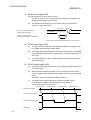
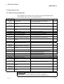
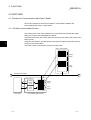
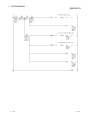
1
PROFIBUS-DP Slave Module type A1SJ71PB93D , User s Manual MODEL A1SJ71PB93D-U-S-E MODEL CODE 13JR47 PROFIBUS-DP Slave Module type A1SJ71PB93D , User s Manual SH(NA)-080195-A(0109)MEE HEAD OFFICE : 1-8-12, OFFICE TOWER Z 14F HARUMI CHUO-KU 104-6212,JAPAN NAGOYA WORKS : 1-14 , YADA-MINAMI 5 , HIGASHI-KU, NAGOYA , JAPAN When exported from Japan, this manual does not require application to the Ministry of Economy, Trade and Industry for service transaction permission. Specifications subject to change without notice. Mitsubishi Programmable Controller • SAFETY PRECAUTIONS • (Read these precautions before using.) Before using this product, please read this manual and the relevant manuals introduced in this manual carefully and pay full attention to safety to handle the product correctly. The instructions given in this manual are concerned with this product. For the safety instructions of the programmable controller system, please read the CPU module user's manual. In this manual, the safety instructions are ranked as "DANGER" and "CAUTION". DANGER Indicates that incorrect handling may cause hazardous conditions, resulting in death or severe injury. ! CAUTION Indicates that incorrect handling may cause hazardous conditions, resulting in medium or slight personal injury or physical damage. ! Note that the ! CAUTION level may lead to a serious consequence according to the circumstances. Always follow the instructions of both levels because they are important to personal safety. Please save this manual to make it accessible when required and always forward it to the end user. [DESIGN PRECAUTIONS] ! DANGER • When a communication error occurs in the PROFIBUS network, the status of the faulty station is as follows. Configure an interlock circuit in the sequence program using the communication status information (input X1) so that the system can operate safely. Erroneous outputs and mis-operation could cause accidents. (1) The input data from the master station remains unchanged from the data prior to the communication error. (2) When the master station becomes faulty, the output status of the A1SJ71PB93D will be as in the parameter settings of the master station. (3) When any A1SJ71PB93D is down, the output state of other slave stations will be in accordance with the parameter settings of the master station. • Do not output the "prohibited to use" signal as the output signal to an special function module from the PLC CPU. Writing data into the "system area" or outputting a signal for "prohibited to use" may cause system malfunction in the PLC. ! CAUTION • When the PROFIBUS cable is laid, do not lay it close to main circuits or power lines. They should be installed 100mm(3.9inch) or more from each other. Not doing so could result in noise that would cause malfunctioning. A-1 A-1 [INSTALLATION PRECAUTIONS] ! CAUTION • Use the PLC in the environment defined in the general specifications given in this manual. Using this PLC in an environment outside the range of the general specifications may cause electric shock, fire, malfunction, and damage to or deterioration of the product. • Load the module by securely inserting the module fixing hook at the bottom of the module into the fixing hole of the base unit. Always screw the module to the base unit to the specified torque. • Tighten the screws within the range of specified torque. If the screws are loose, it may cause the module to fallout, short circuits, or malfunction. If the screws are tightened too much, it may cause damage to the screw and/or the module, resulting in fallout, short circuits or malfunction. • Switch all phases of the external power supply off when mounting or removing the module. Not ding so may cause electric shock or damage to the module. • Do not touch the conductive area or electric parts of the module. Doing so may cause module malfunctioning or breakdowns. [WIRING PRECAUTIONS] ! CAUTION • Switch all phases of the external power supply of the PLC system off before connecting the PROFIBUS cable. If you not switch off the external power supply, it will cause failure or malfunction of the module. • Be careful not to let foreign matter such as filings or wire chips get inside the module. These can cause fire, breakdowns and malfunctioning. • The PROFIBUS cable which is connected to the module must be protected with a duct or secured in position with clamps. Unless the cable is thus protected or secured, the module or the cable could be damaged when the cable swings, moves or it is strained with careless pulls, or it could cause malfunction when the cable contacts with any undesirable objects. • When disconnecting the PROFIBUS cable from the module, do not pull by holding the cable section. To disconnect the cable, make sure to hold the connector which is coupled with the module. Do not attempt to pull the cable to disconnect it from the module. It could damage the module or the cable, or cause malfunction due to a poor contact of the cable. A-2 A-2 [STARTING AND MAINTENANCE PRECAUTIONS] ! DANGER • Switch all phases of the external power supply off before cleaning. Not doing so could cause electric shock. ! CAUTION • Never disassemble or modify the module. This may cause breakdowns, malfunctioning, injury and/or fire. • Switch all phases of the external power supply off before mounting or removing the module. If you do not switch off the external power supply, it will cause breakdowns or malfunction of the module. [DISPOSAL PRECAUTIONS] ! CAUTION • When disposing of this product, treat it as industrial waste. A-3 A-3 REVISIONS * The manual number is given on the bottom left of the back cover. Print Date Sep., 2001 Nov., 2001 * Manual Number SH (NA) 080195-A First printing SH (NA) 080195-B Correction Revision Section 1.1, Section 3.5.2, Section 5.3, Section 7.3.1, Section 7.3.2 Japanese Manual Version SH-080194-A This manual confers no industrial property rights or any rights of any other kind, nor does it confer any patent licenses. Mitsubishi Electric Corporation cannot be held responsible for any problems involving industrial property rights which may occur as a result of using the contents noted in this manual. 2001 MITSUBISHI ELECTRIC CORPORATION A-4 A-4 INTRODUCTION Thank you for purchasing the Mitsubishi Programmable Controller MELSEC-A Series. Before using the equipment, plese read this manual carefully to develop full familiarity with the functions and performance of the graphic operation terminal you have purchased, so as to ensure correct use. Please forward a copy of this manual to the end user. CONTENTS SAFETY PRECAUTIONS.............................................................................................................................A REVISIONS ...................................................................................................................................................A INTRODUCTION...........................................................................................................................................A CONTENTS...................................................................................................................................................A About Manuals ..............................................................................................................................................A About the Generic Terms and Abbreviations ...............................................................................................A Definitions of the Terms ................................................................................................................................A Product Structure ..........................................................................................................................................A 1 OVERVIEW 1 4 5 5 7 8 8 8 1- 1 to 1- 2 1.1 A1SJ71PB93D Features........................................................................................................................ 1 - 1 2 SYSTEM CONFIGURATION 2- 1 to 2- 2 2.1 Adaptive System ..................................................................................................................................... 2- 1 2.2 Precautions for Configuring a System.................................................................................................... 2- 2 3 SPECIFICATIONS 3- 1 to 3-23 3.1 General Specifications ............................................................................................................................ 3- 1 3.2 Performance Specifications .................................................................................................................... 3- 2 3.3 Network Configuration ............................................................................................................................ 3- 3 3.3.1 Basic configuration ........................................................................................................................... 3- 3 3.4 I/O Signal................................................................................................................................................. 3- 4 3.4.1 I/O signal list ..................................................................................................................................... 3- 4 3.4.2 I/O signal detail description ............................................................................................................. 3- 5 3.5 Buffer Memory List ................................................................................................................................. 3-11 3.5.1 Buffer memory/configuration............................................................................................................ 3-11 3.5.2 Buffer memory detail description ..................................................................................................... 3-12 3.6 Parameters.............................................................................................................................................. 3-18 3.6.1 Data module setting ......................................................................................................................... 3-19 3.6.2 Data assignment mode setting ........................................................................................................ 3-21 3.6.3 Swap setting ..................................................................................................................................... 3-22 3.7 Operation Mode ...................................................................................................................................... 3-23 4 FUNCTIONS 4- 1 to 4- 7 4.1 Functions for Communication with Class 1 Master................................................................................ 44.1.1 I/O data communication function ..................................................................................................... 44.1.2 Global control functions.................................................................................................................... 44.1.3 Word data swapping function .......................................................................................................... 4A-5 A-5 1 1 2 6 5 PROCEDURES BEFORE SYSTEM OPERATION 5- 1 to 5- 7 5.1 Procedures before Operation ................................................................................................................. 55.1.1 Parameter setting to master station................................................................................................. 55.2 Installation ............................................................................................................................................... 55.2.1 Handling precautions ....................................................................................................................... 55.3 Part Names and Settings........................................................................................................................ 55.4 Execution Method for Self-diagnosis...................................................................................................... 55.5 Wiring....................................................................................................................................................... 55.5.1 PROFIBUS cable wiring................................................................................................................... 55.5.2 Precautions against wiring ............................................................................................................... 56 TRANSMISSION DELAY TIME 1 2 3 3 4 5 6 6 7 6- 1 to 6- 2 6.1 Transmission Delay Time of Output Receive......................................................................................... 6- 1 6.2 Transmission Delay Time of Input Send ................................................................................................ 6- 1 7 PROGRAMMING 7- 1 to 7-11 7.1 Communication Sequence..................................................................................................................... 7 - 1 7.2 Station Number Setting (Set to station number 1) ................................................................................ 7 - 2 7.3 Communication of I/O Data ................................................................................................................... 7 - 3 7.3.1 Batch assignment mode ................................................................................................................. 7 - 3 7.3.2 Split assignment mode.................................................................................................................... 7 - 7 7.4 Global Control-driven Program Execution............................................................................................. 7 -11 8 TROUBLESHOOTING 8- 1 to 8- 5 8.1 LED-indicated Error Causes and Actions................................................................................................ 88.2 Checks and Actions for Network-related Faults...................................................................................... 88.3 Causes of Failure to Make Normal Data Communication and Actions to Be Taken............................. 88.4 Error Code List ......................................................................................................................................... 8APPENDIX 1 2 3 4 App - 1 to App - 2 Appendix 1 Outline Drawings ...................................................................................................................App - 1 INDEX A-6 Ind - 1 to Ind - 2 A-6 About Manuals The following are manuals related to this product. Request for the manuals as needed according to the chart below. Related Manuals Manual Name Manual Number Type AJ71PB92D/A1SJ71PB92D PROFIBUS-DP Interface module User's Manual IB-66773 (13JL20) Describes the system configuration, specifications, functions and programming of the AJ71PB92D/A1SJ71PB92D. (Option) PROFIBUS-DP Interface module User's Manual Describes the system configuration, specifications, functions and programming of the QJ71PB92D. SH-080127 (13JR22) (Option) A-7 A-7 About the Generic Terms and Abbreviations Unless otherwise specified, this manual uses the following generic terms and abbreviations to describe the Type A1SJ71PB93D PROFIBUS-DP slave module. Generic Term/Abbreviation A1SJ71PB93D QJ71PB92D AJ71PB92D A1SJ71PB92D Description of the abbreviation/general terms Abbreviated name of Type A1SJ71PB93D PROFIBUS-DP slave module Abbreviated name of Type QJ71PB92D PROFIBUS-DP interface module Abbreviated name of Type AJ71PB92D PROFIBUS-DP interface module Abbreviated name of Type A1SJ71PB92D PROFIBUS-DP interface module Generic name of MELSEC-A series main base unit and extension base unit compatible with A1SJ71PB93D Abbreviated name of PROFIBUS-DP network Abbreviated name of class 1 master station (master/device) in PROFIBUS-DP network Abbreviated name of class 2 master station (master/device) in PROFIBUS-DP network Generic name of class 1 and class 2 master stations Abbreviated name of slave station (slave device) inside PROFIBUS-DP network Base unit PROFIBUS-DP Class 1 master station Class 2 master station Master station Slave station Definitions of the Terms The terms used in this manual have the following meanings and definitions. Term Definition Station number Expansion trouble information I/O configuration information (Data module) Input data Output data Communication WDT Module WDT "FDL Address" in the PROFIBUS specification "Extended Diagnostic Information" in the PROFIBUS specification "Configuration Data" in the PROFIBUS specification Data sent by the A1SJ71PB93D and received by the master station (data input by the master station) Data sent by the master station and received by the A1SJ71PB93D (data output by the master station) Watchdog timer set in the slave parameter of the master station Watchdog timer in the A1SJ71PB93D Product Structure The product structure of this product is given in the table below. Model A1SJ71PB93D A-8 Product Name Type A1SJ71PB93D PROFIBUS-DP slave module Quantity 1 A-8 1 OVERVIEW MELSEC-A 1 OVERVIEW This is the user's manual for the A1SJ71PB93D PROFIBUS-DP slave module (hereafter abbreviated as " A1SJ71PB93D"), which is used to connect a MELSECA/QnA series programmable controller to a PROFIBUS-DP network. The A1SJ71PB93D operates as a slave station in the PROFIBUS-DP network. 1.1 A1SJ71PB93D Features (1) Conformance with EN50170 Volume 2 (Part 1, 2, 3, 4, 8) The module conforms with EN50170 Volume 2 (Part 1, 2, 3, 4, 8) and can communicate with the master station as a PROFIBUS-DP slave station. (2) I/O data communication with class 1 master station The module can communicate I/O data with the class 1 master station (master station that makes data communication cyclically with a slave station) of PROFIBUS-DP. One A1SJ71PB93D can communicate up to 122 words of input or output data or a total of 192 words of input and output data. Class 1 master station Output image Input image PROFIBUS-DP network Buffer memory FROM TO CPU module 1-1 Output receive area Output image Input send area Input image A1SJ71PB93D (slave station) 1-1 1 1 OVERVIEW MELSEC-A (3) Swapping of I/O data When I/O data is sent/received from/to the master station, their upper and lower bytes can be swapped. Though PROFIBUS-DP handles the upper and lower bytes of I/O data differently depending on the master station type, the I/O data need not be swapped in a sequence program. 1 (4) Start/stop of refreshing the input send area Refreshing of send data from the A1SJ71PB93D to the master station is controllable by an output signal (Y00). Providing interlocks disables illegal data from being sent to the master station at error occurrence. (5) Extended fault notification function Data stored in the extended fault information area of the buffer memory can be sent to the master station as extended fault information when the host is faulty, for example. When the host is not faulty anymore, notify the master station that there is no fault. : Diagnostics Information (device-related fault information set by the user as desired) (6) Compatibility with global control function Compatibility with the global control function allows the updating of I/O data at the A1SJ71PB93D to be controlled from the class 1 master station using the command (SYNC, UNSYNC, FREEZE, UNFREEZE) sent by the class 1 master. (7) Communication with class 2 master station The following communications can be made with the class 2 master station (master station designed for network management to perform booting, maintenance and diagnostics) of PROFIBUS-DP. • Read from input send area/output receive area • Read of I/O configuration information • Station number change For the way to use each function, refer to the manual of the class 2 master station used. 1-2 1-2 2 SYSTEM CONFIGURATION MELSEC-A 2 SYSTEM CONFIGURATION This chapter describes the system configuration of A1SJ71PB93D. 2.1 Adaptive System 2 (1) Adaptive CPU modules • A1SCPU • A1SJHCPU • A2USHCPU-S1 • Q2ASCPU(S1) • A1SCPUC24-R2 • A1SJCPU(S3) • A2SCPU • A2SHCPU • Q02CPU-A • Q02HCPU-A • Q2ASHCPU(S1) • A1SHCPU • A2ASCPU(S1) • Q06HCPU-A (2) Number mountable Any number of modules can be used, provided the number of I/O points of the appilcable CPU is not exceeded. (3) Available slots Any slot in the base unit can be used, provided the following consideration is not a problem. When mounting moduIes in an extension base unit that does not have a power supply (A1S52B(S1), A1S55B(S1), A1S58B(S1)), the power supply capacity may be insufficient. When mounting an A1SJ71PB93D to an extension base unit, and extension base unit after carefully considering the following factors: 1) Current capacity of the power supply module on the main base unit 2) Voltage drop at the main base unit 3) Voltage drop at the extension base unit 4) Voltage drop in the extension cable (4) Applicable cable Use the following twisted pair cable provided with a shield that conforms to EN50170 Volume 2 : type A. Item Impedance Capacity Conductor resistance Conductor sectional area Specifications 135 to 160 Ω (f = 3 to 20 MHz) < 30 pF/m < 110 Ω/km ≥ 0.34 mm2 (22AWG) (5) Termination resistor Use the following termination resistor that conforms to EN50170 Volume 2 : type A. • RtA = 220 Ω ± 2%, min. 1/4 W • Ru = Rd = 390 Ω ± 2%, min. 1/4 W : The A1SJ71PB93D does not have a built-in termination resistor. Refer to Section 5.5.1 for the wiring of the termination resistor. REMARK For the way to calculate the I/O point range and voltage drop, refer to the user's manual of the CPU module used. 2-1 2-1 2 SYSTEM CONFIGURATION MELSEC-A 2.2 Precautions for Configuring a System (1) When performing the following operations, ensure that the module READY signal X1D of A1SJ71PB93D is turned ON beforehand. To switch over the operation mode with Y11/X11, using the sequence program. If the status of X1D is ignored and data is read from or written in the buffer memory, the CPU module may detect an error to stop the sequence calculation. 2 (2) 2-2 The A1SJ71PB93D cannot be used on a remote I/O station of MELSECNET(II) or MELSECNET/10. 2-2 3 SPECIFICATIONS MELSEC-A 3 SPECIFICATIONS This chapter describes the general specifications, performance specifications, network configuration, I/O signals, buffer memory, parameters and operation modes of the A1SJ71PB93D. 3.1 General Specifications The flowing table shows the general specifications of the A1SJ71PB93D. Item Specifications Operating ambient 3 0 to 55 °C temperature Storage ambient -20 to 75 °C temperature Operating ambient 10 to 90 % RH, No condensation humidity Storage ambient 10 to 90 % RH, No condensation humidity Conforming Vibration to *JIS B resistance 3501, IEC 1132-2 ------- Frequency Acceleration Amplitude When there is 10 to 57 Hz --- 0.075 mm 57 to 150 Hz 9.8 m/s --- 10 to 57 Hz --- 0.035 mm 57 to 150 Hz 4.9 m/s intermittent vibration When there is continuous vibration Shock resistance 2 2 --- Sweep Count 10 times each in X, Y and Z axis (80 minutes) 2 Conforming to JIS B3501, IEC 61131-2 (147 m/s , 3 times each in 3 directions) Operating environment No corrosive gas present Operating height 2000 m(6562 ft) or less Installation area On the control board Over-voltage category *1 Pollution rate *2 II or less 2 or less *1: Indicates the distribution area where the device is assumed to be connected, from the public power distribution network to the local machine device. Category II is applied to the devices to which the power is supplied from a fixed equipment. The surge resistance voltage of a rated 300 V device is 2500 V. *2: This is an index which indicates the occurrence rate of the conductive object in the environment where the device is used. Pollution rate II indicates that only non-conductive pollution may occur with a possibility of generating temporary conductivity due to accidental condensation. 3-1 3-1 3 SPECIFICATIONS MELSEC-A 3.2 Performance Specifications Item Specifications Model PROFIBUS-DP station type A1SJ71PB93D Slave station Electrical standards and characteristics Complies with EIA-RS485 Medium Shielded twisted cable (Type A) Network configuration Bus (however, tree type when a repeater is used) Data link method Polling method Transmission encoding method NRZ Transmission speed Transmission distance [m/segment] Transmission specifications 3 Maximum transmission distance when 3 repeaters are used 9.6 [kbps] 19.2 [kbps] 45.45 [kbps] Transmission speed/maximum transmission distance 1 2 1200 4800 93.75 [kbps] 187.5 [kbps] 1000 4000 500 [kbps] 400 1600 1500 [kbps] 200 800 100 400 3 [Mbps] 6 [Mbps] 12 [Mbps] Maximum number of repeaters/network 3 units Maximum number of stations/segment 32 stations (including repeaters) Number of connection nodes/segments 32 Station numbers that may be set 0 to 125 Max. number of data that may be communicated Number of I/O data is 192 words in total. (Number of input or output data is up to 122 words.) Flash ROM write count 2 3 Max. 10000 times Number of occupied I/O 32 points (I/O assignment : 32 special points) 5VDC Internal power consumption (A) 0.36 External dimensions (mm) 130(H) × 34.5(W) × 93.6(D) Weight (kg) 0.18 1 Transmission speed control within +/- 0.3% (EN50170 Volume 2 compliant) 2 Distance that the transmission distance can be expanded by (m/network) using repeaters Transmission distance (m/network) = (number of repeaters + 1) × transmission distance (m/segment) 3 Factory-set to "126" (EN50170 Volume 2 compliant) For the noise immunity, withstand voltage, insulation resistance and others in the PLC system using this module, refer to the power supply module specifications given in the used CPU module user’s manual. 3-2 3-2 3 SPECIFICATIONS MELSEC-A 3.3 Network Configuration This section provides the basic network configuration of PROFIBUS-DP using the A1SJ71PB93D. 3.3.1 Basic configuration 1) Equipment types A1SJ71PB93D (slave station) Class 1 master station Repeater 2) Number of units that can be connected to the entire network (when repeaters are used) Master+slave ≤ 126 units 3) Number that can be connected for 1 segment Master+slave+repeaters ≤ 32 units 4) Communications can be conducted via a maximum of 3 repeaters from an arbitrary master or arbitrary slave to an arbitrary master or arbitrary slave (Not 3 units in the entire network). 5) The maximum number of slave stations that may be connected to one master station depends on the specifications of the master station. Class 1 Master station CPU A1SJ71 module PB93D Slave Station No. 1 Slave Station No. 2 Slave Station No. 30 Repeater CPU A1SJ71 module PB93D Slave Station No. 31 Slave Station No. 32 Slave Station No. 60 Prepare the PROFIBUS-DP cable and termination resistor on the user side. 3-3 3-3 3 SPECIFICATIONS MELSEC-A 3.4 I/O Signal 3.4.1 I/O signal list The I/O signal configuration used in the A1SJ71PB93D and the data communications with the PLC CPU are described below. The I/O numbers (X/Y) indicated in this chapter and later assume that 0 is set as the first I/O number of the A1SJ71PB93D. Signal direction: A1SJ71PB93D Device No. PLC CPU Description Signal direction: PLC CPU Device No. A1SJ71PB93D Description X00 Not usable Y00 Input send area refresh directive X01 I/O communication Y01 Not usable X02 Expansion trouble notification completion Y02 Expansion trouble notification request X03 Module error Y03 Module error reset request X04 Not usable Y04 X05 SYNC mode Y05 X06 SYNC receive Y06 X07 FREEZE mode Y07 X08 Y08 X09 X0A Y09 Not usable Y0A X0B Y0B X0C Y0C X0D Module WDT error X0E X0F Not usable Y0D Y0E Not usable Y0F X11 Operation mode change completion Y11 X12 Not usable Y12 Not usable X13 Station number setting completion Y13 Station number setting request X10 Y10 X14 Y14 X15 Y15 X16 Y16 X17 X18 Y17 Not usable Y18 X19 Y19 X1A Y1A X1B Y1B X1C Y1C X1D X1E X1F Operation mode change request Module ready Not usable Y1D Y1E Not usable Y1F POINT If a device which is not usable is accidentally turned on and off in the sequence program, it cannot guarantee as the A1SJ71PB93D function. 3-4 3-4 3 SPECIFICATIONS MELSEC-A 3.4.2 I/O signal detail description (1) I/O communication signal (X01) (a) This signal turns on when the module is ready to communicate with the master station properly. (b) While the I/O communication signal (X01) is on, the output receive area is updated to the output data sent from the master station. (It is independent of the status of the input send refresh directive signal (Y00).) (c) This signal turns off when a communication time-out error occurs due to a stop of communication with the master station. However, if the communication WDT setting in the master station side parameters is "invalid", the I/O communication signal does not turn off since a communication time-out error does not occur. (The output data in the output receive area is held.) Communication WDT Setting in Master Station Side Parameters 0: Invalid 1 to 65000: Valid Operation at Master Station Fault No error (I/O communication signal (X01) remains on) Communication time-out error occurrence (I/O communication signal (X01) turns off) The communication WDT setting can be confirmed in the "Current communication WDT value (buffer memory address: 2257 (8D1H))" of the A1SJ71PB93D. (d) Use this signal as a signal for interlocking output receive area read performed with the FROM instruction. (2) Expansion trouble notification completion signal (X02) (a) This signal turns on at completion of expansion trouble notification started by the expansion trouble notification request signal (Y02). (While the I/O communication signal (X01) is off, the expansion trouble notification completion signal (X02) does not turn on since an expansion trouble notification request is ignored.) (b) Turning off the expansion trouble notification request signal (Y02) turns off the expansion trouble notification completion signal (X02). I/O communication signal (X01) Expansion trouble notification request signal (Y02) Expansion trouble notification completion signal (X02) Expansion trouble information area (Buffer memory address : 2041 to 2053 (7f9H to 805H)) 3-5 Expansion trouble notification request Expansion trouble notification completion TO Expansion trouble information write 3-5 3 SPECIFICATIONS MELSEC-A (3) Module error signal (X03) (a) This signal turns on when an error occurs. At this time, an error code is stored into the module error information area (buffer memory address: 2040 (7F8H)). (b) This signal turns off when the error is reset by the error reset request signal, PLC CPU reset or like. Error reset Error reset request signal (Y03) Error detection Module error signal (X03) FROM Module error information area (Buffer memory address : 2040(7F8H)) The error code is read from the buffer memory to the PLC CPU. (4) SYNC mode signal (X05) (a) This signal turns on when the A1SJ71PB93D is placed in the SYNC mode by a SYNC request from the master station. (b) The SYNC mode signal (X05) turns off when the SYNC mode is terminated by an UNSYNC request from the master station, a communication stop or a CPU reset. (c) The SYNC LED turns on/off in synchronization with the on/off of the SYNC mode signal (X05). (5) SYNC receive signal (X06) (a) The SYNC receive signal (X06) turns on on receipt of a SYNC request from the master station. (b) While the SYNC mode signal (X05) is on, the receipt of a SYNC request from the master station changes the on/off state of the SYNC receive signal (X06). At this time, the SYNC mode signal (X05) remains on. (c) The SYNC receive signal (X06) turns off when the SYNC mode is terminated by an UNSYNC request from the master station, a communication stop or a CPU reset. SYNC request SYNC request SYNC request UNSYNC request Request from master SYNC mode signal (X05) SYNC receive signal (X06) SYNC LED 3-6 Off On Off 3-6 3 SPECIFICATIONS MELSEC-A (6) FREEZE mode signal (X07) (a) The FREEZE mode signal (X07) turns on when the A1SJ71PB93D is placed in the FREEZE mode by a FREEZE request from the master station. (b) The FREEZE mode signal (X07) turns off when the FREEZE mode is terminated by an UNFREEZE request from the master station, a communication stop or a CPU reset. (c) The FREEZE LED turns on/off in synchronization with the on/off of the FREEZE mode signal (X07). FREEZE reqest UNFREEZE reqest Reqest from master FREEZE mode signal (X07) FREEZE LED Off On Off (7) Module WDT error signal (X0D) (a) This signal turns on when a module WDT error occurs. (b) This signal turns off when the PLC CPU is reset or the A1SJ71PB93D power is switched from OFF to ON. The module WDT error signal (X0D) is not turned off by an error reset made by the error reset request signal (Y03). (8) Operation mode change completion signal (X11) (a) This signal turns on at completion of an operation mode change started by the operation mode change request signal (Y11). At this time, the result is stored into the operation mode change result area (buffer memory address: 2256 (8D0H)) of the buffer memory. (b) Turning off the operation mode change request signal (Y11) turns off the operation mode change completion signal (X11). (c) This signal turns on at either normal or abnormal completion of an operation mode change. At abnormal completion, the operation mode change request is made invalid and operation continues in the operation mode that had been used before the change request was given. Input send area refresh directive signal (Y00) Operation mode change request signal (Y11) Operation mode change completion signal (X11) TO instruction Sets the operation mode in "operation mode change request area". 3-7 FROM instruction Checks result in "operation mode change result area" and "current operation mode". 3-7 3 SPECIFICATIONS MELSEC-A (9) Station number setting completion signal (X13) (a) This signal turns on at completion of station number setting started by the station number setting request signal (Y13). (b) Turning off the station number setting request signal (Y13) turns off the station number setting completion signal (X13). (c) Check the setting result in the operation station number area (buffer memory address: 513 (201H)) and module error information area (buffer memory address: 2040 (7F8H)) of the buffer memory. If a station number error (error code: 1002H) has occurred, the station number setting request is made invalid and operation continues with the station number that had been used before the change request was given. (d) Turning on the station number setting request signal (Y13) suspends I/O communication. Turning on the station number setting completion signal (X13) resumes I/O communication. Input send area refresh directive signal (Y00) Station number change request signal (Y13) Station number change completion signal (X13) TO instruction Sets station number in " station number change request area". FROM instruction Checks result in "operation station number area, module error information area". (10) Module ready signal (X1D) 3-8 (a) This signal turns on when the A1SJ71PB93D is enabled for access from the PLC CPU. It is independent of the operation mode at a start. (b) This signal turns off when the A1SJ71PB93D is disabled for access from the PLC CPU due to a module WDT error, hardware fault or like. 3-8 3 SPECIFICATIONS MELSEC-A (11) Input send area refresh directive signal (Y00) (a) Turning on this signal during communication with the master station (I/O communication signal (X01) = ON) resumes data communication of the input send area (buffer memory addresses: 256 to 447 (100H to 1BFH)) in the buffer memory. (b) Turning this signal off stops sending of the data in the input send area to the master station. (0 data are sent.) (c) While the I/O communication signal (X01) is off, ON of the input send area refresh directive signal (Y00) is invalid. Communication stop Communication with master station Communication in progress I/O communication signal (X01) OFF Data in input send area ON Not updated Read from output receive area (FROM instruction) Updated Communication stop OFF Not updated FROM Execution of read from output receive area POINT The following are the relationships between data send and receive of the A1SJ71PB93D, which vary with the states of the I/O communication signal (X01) and input send area refresh directive signal (Y00). X01 State Y00 State Data in Output Receive Area/Input Send Area Master station Input area OFF A1SJ71PB93D No communication Input send area ON/OFF Output area Not updated Master station Input area Output receive area A1SJ71PB93D Sent Input send area ON Output area Updated Output receive area ON Master station Input area A1SJ71PB93D 0 data sent Input send area OFF Output area 3-9 Updated Output receive area 3-9 3 SPECIFICATIONS MELSEC-A (12) Expansion trouble notification request signal (Y02) (a) Turning this signal on sends the data set in the expansion trouble information area (buffer memory address: 2041 to 2053(7F9H to 805H)) to the master station as expansion trouble information. (The expansion trouble notification request is ignored while the I/O communication signal (X01) is off.) (b) When you have checked that the expansion trouble notification completion signal (Y02) is on, turn this signal off in the sequence program. (c) Refer to X02 for the on/off timing. (13) Module error reset request signal (Y03) (a) Turning on the module error reset request signal (Y03) resets the error of the A1SJ71PB93D. (The module error signal (X03) turns off and the ERR. LED goes off.) (b) When you have checked that the module error signal (X03) is off, turn this signal off in the sequence program. (c) Making an error reset clears the error code in the module error information area (buffer memory address: 2040 (7F8H)). (d) Refer to X03 for the on/off timing. (14) Operation mode change request signal (Y11) (a) Turning this signal on gives a request to change to the operation mode set in the operation mode change request area (buffer memory address: 2255 (8CFH)). (b) When you have checked that the operation mode change completion signal (X11) is on, turn this signal off in the sequence program. (c) Refer to X11 for the on/off timing. (15) Station number setting request signal (Y13) (a) Turning this signal on gives a request to change to the station number set in the station number setting request area (buffer memory address: 515 (203H)) of the buffer memory. (b) When you have checked that the station number setting completion signal (X13) is on, turn this signal off in the sequence program. (c) Refer to X13 for the on/off timing. POINT When setting the station number from class 2 master station, specifying "TRUE" for "No_Add_Chg" disables the station number from being changed until the station number is cleared by a station number setting request. 3 - 10 3 - 10 3 SPECIFICATIONS MELSEC-A 3.5 Buffer Memory List 3.5.1 Buffer memory/configuration The configuration of the buffer memory used to receive and send data with the A1SJ71PB93D and the PLC CPU is described below. Buffer memory address decimal (Hexadecimal) Area name 0 (0H) Output receive area 191 (BFH) 192 (C0H) Description Stores the output data received from the master station. (Max. usable range 122 words) Not usable Read/Write Read 255 (FFH) 256 (100H) Input send area 447 (1BFH) 448 (1C0H) Used to set the input data to be sent to the master station. (Max. usable range 122 words) Not usable Write 511 (1FFH) 512 (200H) Operation baud rate Stores the baud rate in current operation. Read 513 (201H) Operation station number Stores the station number in current operation. Read 514 (202H) Station number set on flash ROM Stores the station number saved on the flash ROM. Read 515 (203H) Station number setting request Used to set a new station number to be set in response to the station number setting request signal (Y13). Write 516 (204H) Station number rewritable count to flash ROM Stores the remaining number of times when the station number can be saved onto the flash ROM during continuous operation. Read 517 (205H) Not usable 2039 (7F7H) 2040 (7F8H) Module error information Stores the error code detected by the A1SJ71PB93D. Read Expansion trouble information area Used to set the expansion trouble notification data to the master station. Write Expansion trouble information send result area Stores the result of sending the expansion trouble result to the master station. Read 2041 (7F9H) 2053 (805H) 2054 (806H) 2055 (807H) Not usable 2253 (8CDH) 2254 (8CEH) Current operation mode Stores the operation mode in current operation. Read 2255 (8CFH) Operation mode change request Used to set a new operation mode to be set in response to the operation mode change request signal (Y11). Write 2256 (8D0H) Operation mode change result Stores the result of changing the operation mode in response to the operation mode change request signal (Y11). Read 2257 (8D1H) Current communication WDT value Stores the communication WDT value in current operation. Read 2258 (8D2H) Not usable 2259 (8D3H) Swapping function setting status 2260 (8D4H) Not usable Stores the setting status of the swapping function in current operation. Read 2271 (8DFH) 2272 (8E0H) Output receive area used status area Stores the current used status of the output receive area. Read 2283 (8EBH) 2284 (8ECH) Not usable 2287 (8EFH) 2288 (8F0H) Input send area used status area Stores the current used status of the input send area. Read 2299 (8FBH) 2300 (8FCH) Not usable 2815 (AFFH) POINT Don't read and write to the buffer memory which is not usable. If you perform it, it cannot guarantee as the A1SJ71PB93D function. 3 - 11 3 - 11 3 SPECIFICATIONS MELSEC-A 3.5.2 Buffer memory detail description (1) Output receive area (buffer memory address: 0 (0H) to 191 (BFH)) Stores the output data received from the master station. The structure varies with the data module setting and data assignment mode setting in the parameters. (Refer to Section 3.6.1, Section 3.6.2 and Section 3.6.3) (2) Input send area (buffer memory address: 256 (100H) to 447 (1BFH)) Used to store the input data to be sent to the master station. The structure varies with the data module setting and data assignment mode setting in the parameters. (Refer to Section 3.6.1, Section 3.6.2 and Section 3.6.3) (3) Operation baud rate (buffer memory address: 512 (200H)) Stores the baud rate in current operation. Baud Rate Stored Value Baud rate not yet recognized 0000H 9.6 kbps 96E2H 19.2 kbps 19E3H 45.45 kbps 45E3H 93.75 kbps 93E3H 187.5 kbps 18E4H 500 kbps 05E5H 1500 kbps 15E5H 3 Mbps 03E6H 6 Mbps 06E6H 12 Mbps 12E6H The stored value while the I/O communication signal (X01) is on is valid. Use the master station parameter to set the baud rate of the PROFIBUS-DP. (4) Operation station number (buffer memory address: 513 (201H)) Stores the station number of the A1SJ71PB93D in current operation. The storage range is 0 to 126. If the station number is not set (the station number is as set in the factory or has been cleared), "126" is stored. I/O data cannot be communicated if the station number is not set. When the station number setting request (buffer memory address: 515 (203H)) was used to write the station number to the flash ROM, switching power on or resetting the PLC CPU will store the value written to the flash ROM. 3 - 12 3 - 12 3 SPECIFICATIONS MELSEC-A (5) Station number set on flash ROM (buffer memory address: 514 (202H)) Stores the station number of the A1SJ71PB93D set to the flash ROM. The storage range is 0 to 125. If the station number is not set to the flash ROM (the station number is as set in the factory or has been cleared), "65535 (FFFFH)" is stored. (6) Station number setting request (buffer memory address: 515 (203H)) Used to set any of the following values when setting a new station number of the A1SJ71PB93D in response to the station number setting request signal (Y13). Set Value Description 0 (0000H) Sets a new station number. (Not saved onto the flash ROM) 125 (007DH) 256 (0100H) 381 (017D0H) 65535 (FFFFH) Sets 256 (0100H) + new station number. (Saved onto the flash ROM) Example: To change to station No. 12 256 (0100H) + 12 (new station number) = 268 (010CH) Clears the station number. After clearing, the operation station number is "126". The station number set to the flash ROM is "FFFEH". "65534 (FFFEH)" is stored at power-on or PLC CPU reset. If a station number setting request is executed with a value other than any of the above, a station number error (error code: 1002H) occurs. (7) Station number rewritable count to flash ROM (buffer memory address: 516 (204H)) Stores the remaining number of times when the station number setting can be saved onto the flash ROM during operation. When the PLC CPU is reset, the A1SJ71PB93D is powered on, or the station number is cleared, the remaining number of times is set to 60. Every time the station number is saved onto the flash ROM, the remaining number of times is decremented by 1. If an attempt is made to rewrite the station number on the flash ROM at the remaining count of 0, a station number rewritable count excess error (error code: 2001H) occurs and the station number on the flash ROM is not changed. If the station number rewritable count excess error has occurred, switch power on again, reset the PLC CPU, or clear the station number on the flash ROM using the station number setting request signal (Y13). (This returns the remaining count to 60 times.) (When the station number for a station number setting request is the same as the one saved on the flash ROM (buffer memory address: 514 (202H)), the remaining count does not decrease.) POINT When a station number rewritable count excess error has occurred, the remaining count remains 0 if an error reset request (Y03) is given. (The module error signal (X03) and ERR. LED turn off.) After clearing the station number, make an error reset request (Y03). 3 - 13 3 - 13 3 SPECIFICATIONS MELSEC-A (8) Module error information (buffer memory address: 2040 (7F8H)) Stores the error code of the error that occurred in the A1SJ71PB93D. Refer to Section 8.4 for the error codes. (9) Expansion trouble information area (buffer memory address: 2041 (7F9H) to 2053 (805H)) Used to set the expansion trouble information to be sent to the master station. (The expansion trouble information sent by the A1SJ71PB93D is the Device Related Diagnostic specified in PROFIBUS.) The expansion trouble information can be set in a sequence program. Data length : Data length of the data to be sent as expansion trouble information (byte unit) Expansion trouble information : Any data to be set to the master station (max. 24 bytes) 2041(7F9H) 2042(7FAH) 2053(805H) Data length Expansion trouble information The extended fault information area is used as described below when an extended fault occurs and when the extended fault is removed. (a) When extended fault occurs When the host becomes faulty, for example, the data stored in the extended fault information area of the buffer memory is sent to the master station as extended fault information. In the following procedure, the A1SJ71PB93D can notify the master station of the extended fault of the host. 1) In the buffer memory 2042 (7FAH), set the data to be sent to the master station. 2) In the buffer memory 2041 (7F9H), set the length of the data to be sent to the master station. 3) Turn ON the extended fault information notification request (Y02). 4) After the extended fault information notification completion (X02) has turned ON, turn OFF the extended fault information notification request (Y02). (b) 3 - 14 When extended fault is removed When the host is not faulty anymore, notify the master station that there is no fault. In the following procedure, the A1SJ71PB93D can notify the master station that the extended fault of the host has been removed. 1) In the buffer memory 2041 (7F9H), set the data length 0. 2) Turn ON the extended fault information notification request (Y02). 3) After the extended fault information notification completion (X02) has turned ON, turn OFF the extended fault information notification request (Y02). 3 - 14 3 SPECIFICATIONS MELSEC-A (10) Current operation mode (buffer memory address: 2254 (8CEH)) Stores the current operation mode. Refer to Section 3.7 for the operation mode. Stored Value Mode 0000H Normal operation mode 0002H Self-diagnostic mode At power-on or PLC CPU reset, the module starts in the normal operation mode. (11) Operation mode change request (buffer memory address: 2255 (8CFH)) Set any of the following values when changing the operation mode of the A1SJ71PB93D with the operation mode change request signal (Y11). Set Value Description 0000H Normal operation mode 0002H Self-diagnostic mode At power-on or PLC CPU reset, "FFFEH" is stored. If an operation mode change request is executed with any value other than the set value, the operation cannot be guaranteed. (12) Operation mode change result (buffer memory address: 2256 (8D0H)) Stores the result of changing the operation mode in response to the operation mode change request signal (Y11). 0 : Normal completion 1 : Abnormal completion (A change request was made with an illegal value set in the operation mode change request area) (13) Current communication WDT value (buffer memory address: 2257 (8D1H)) Stores the communication WDT value set in the master side parameters. The stored value is invalid if the I/O communication signal (X01) is off. 0 : Communication WDT setting invalid Other than 0 : Communication WDT setting (in increments of 10ms) When the communication WDT setting is invalid, the I/O communication signal (X01) does not turn off since the communication WDT does not count up if the master station becomes faulty during communication. (14) Swapping function setting status (buffer memory address: 2259 (8D3H)) Stores the setting status of the swapping function set in the master side parameter. 0 : Without swap setting 1 : With swap setting The stored value while the I/O communication signal (X01) is on is valid. 3 - 15 3 - 15 3 SPECIFICATIONS MELSEC-A (15) Output receive area used status area (buffer memory address: 2272 to 2283 (8E0H to 8EBH)) Stores the used status of the output receive area. The bits corresponding to the buffer memory addresses in use turn on. The stored value while the I/O communication signal (X01) is on is valid. Buffer Memory Address Decimal (Hexadecimal) b15 Corresponding Buffer Memory Addresses b14 b13 b12 b11 b10 b9 b8 b7 b6 b5 b4 b3 b2 b1 2272(8E0H) 15 14 13 12 11 10 9 8 7 6 5 4 3 2 1 b0 0 2273(8E1H) 31 30 29 28 27 26 25 24 23 22 21 20 19 18 17 16 2274(8E2H) 47 46 45 44 43 42 41 40 39 38 37 36 35 34 33 32 2275(8E3H) 63 62 61 60 59 58 57 56 55 54 53 52 51 50 49 48 2276(8E4H) 79 78 77 76 75 74 73 72 71 70 69 68 67 66 65 64 2277(8E5H) 95 94 93 92 91 90 89 88 87 86 85 84 83 82 81 80 2278(8E6H) 111 110 109 108 107 106 105 104 103 102 101 100 99 98 97 96 2279(8E7H) 127 126 125 124 123 122 121 120 119 118 117 116 115 114 113 112 2280(8E8H) 143 142 141 140 139 138 137 136 135 134 133 132 131 130 129 128 2281(8E9H) 159 158 157 156 155 154 153 152 151 150 149 148 147 146 145 144 2282(8EAH) 175 174 173 172 171 170 169 168 167 166 165 164 163 162 161 160 2283(8EBH) 191 190 189 188 187 186 185 184 183 182 181 180 179 178 177 176 • Example of output receive area used status Buffer memory Area name Address decimal (Hexadecimal) 0 (0H) 1 (1H) 14 (EH) 15 (FH) Output receive area 16 (10H) 17 (11H) 30 (1EH) 31 (1FH) 32 (20H) b15 b14 b13 b12 b11 b10 b9 b8 b7 b6 b5 b4 b3 b2 b1 b0 Output receive area used status areas 2272 (8E0H) 0 1 0 0 0 0 0 0 0 0 0 0 0 0 0 1 2273 (8E1H) 1 0 0 0 0 0 0 0 0 0 0 0 0 0 1 0 2274 (8E2H) 0 0 0 0 0 0 0 0 0 0 0 0 0 0 0 0 Areas where output data are being received from master station 3 - 16 3 - 16 3 SPECIFICATIONS MELSEC-A (16) Input send area used status area (buffer memory address: 2288 to 2299 (8F0H to 8FBH)) Stores the used status of the input send area. The bits corresponding to the buffer memory addresses in use turn on. The stored value while the I/O communication signal (X01) is on is valid. Buffer Memory Address Decimal (Hexadecimal) b15 Corresponding Buffer Memory Addresses of Input Send Area (Decimal) b14 b13 b12 b11 b10 b9 b8 b7 b6 b5 b4 b3 b2 b1 b0 2288(8F0H) 271 270 269 268 267 266 265 264 263 262 261 260 259 258 257 256 2289(8F1H) 287 286 285 284 283 282 281 280 279 278 277 276 275 274 273 272 2290(8F2H) 303 302 301 300 299 298 297 296 295 294 293 292 291 290 289 288 2291(8F3H) 319 318 317 316 315 314 313 312 311 310 309 308 307 306 305 304 2292(8F4H) 335 334 333 332 331 330 329 328 327 326 325 324 323 322 321 320 2293(8F5H) 351 350 349 348 347 346 345 344 343 342 341 340 339 338 337 336 2294(8F6H) 367 366 365 364 363 362 361 360 359 358 357 356 355 354 353 352 2295(8F7H) 383 382 381 380 379 378 377 376 375 374 373 372 371 370 369 368 2296(8F8H) 399 398 397 396 395 394 393 392 391 390 389 388 387 386 385 384 2297(8F9H) 415 414 413 412 411 410 409 408 407 406 405 404 403 402 401 400 2298(8FAH) 431 430 429 428 427 426 425 424 423 422 421 420 419 418 417 416 2299(8FBH) 447 446 445 444 443 442 441 440 439 438 437 436 435 434 433 432 • Example of input send area used status Buffer memory Area name Address decimal (Hexadecimal) 256 (100H) 257 (101H) 270 (10EH) Input send area 271 (10FH) 272 (110H) 273 (111H) 286 (11EH) 287 (11FH) 288 (120H) b15 b14 b13 b12 b11 b10 b9 b8 b7 b6 b5 b4 b3 b2 b1 b0 Input send area used status area 2288 (8F0H) 1 0 0 0 0 0 0 0 0 0 0 0 0 0 1 0 2289 (8F1H) 0 1 0 0 0 0 0 0 0 0 0 0 0 0 0 1 2290 (8F2H) 0 0 0 0 0 0 0 0 0 0 0 0 0 0 0 0 Areas where input data are being sent to master station 3 - 17 3 - 17 3 SPECIFICATIONS MELSEC-A 3.6 Parameters PROFIBUS-DP requires the slave station parameters to be set to the master station as slave parameters. The following table indicates the slave parameters for the A1SJ71PB93D to be set to the master station. Setting Destination AISJ71 PB93D Item Description Refer To Set the station number of the A1SJ71PB93D. FDL Address • Setting range 0 to 125 Set the watchdog timer period of the communication WDT. Watchdog • Setting range 0 : Communication WDT setting invalid 2 to 65000 : Communication WDT setting valid (set value 10ms) Set the minimum response time until the reply frame can be sent to the master Min T_sdr station. • Setting range 0 to 125 Group identification Set the group to which the module belongs. number The module can belong to multiple groups (Grp1 to Grp8). Set the I/O configuration information (set to "Cfg_Data" of the master station). Master station Data module setting • Setting type 96 pattern Section 3.6.1 • Number of setting 1 to 40 Data assignment mode setting Set the data layout of the output send area/input receive area of the buffer memory (set to "User_Prm_Data" of the master station). • Setting range Section 3.6.2 0 : Batch assignment mode (default) 1 : Split assignment mode Set whether the word data sent/received on the A1SJ71PB93D side will be swapped or not (set to "User_Prm_Data" of the master station). Swap setting • Setting range Section 3.6.3 0 : Without swap (default) 1 : With swap Set the parameters to the master station with the configurator corresponding to the master station used. (Refer to Section 5.1.1.) 3 - 18 3 - 18 3 SPECIFICATIONS MELSEC-A 3.6.1 Data module setting Set the I/O configuration information of the master station and A1SJ71PB93D. (1) Number of data modules to be set Set the data modules per A1SJ71PB93D within the following range. • Number of data modules: Max. 40 modules • Total data size Input data: Max. 122 words Total max. 192 words Output data: Max. 122 words (2) Data module setting pattern For data module setting, choose the corresponding one from among 96 patterns made available by combining I/O designation (3 types), data size (16 types) and separation prevention setting (2 types). Setting Item Types I/O designation Data size Input, output, input/output 1 to 16 words Separation prevention setting Word unit, data module unit (3) Data module setting example The data module setting example given here assumes the following configuration. • Configuration example Data module 0 CPU module A1SJ71PB93D Input module 64 points (4 words) X20 to X5F Data module 1 Data module 2 Output module 64 points (4 words) Y60 to Y9F I/O module 32 points (2 words) XA0 to XBF YA0 to YBF • Setting example Data Module Setting A1SJ71PB93D Buffer Memory Data module 0 (Input, 4 words, word unit) Data module 1 (Output, 4 words, word unit) Data module 2 (Input/output, 2 words, word unit) Data module 0 area (4 words) is reserved in the input send area. Data module 1 area (4 words) is reserved in the output receive area. Data module 2 areas (2 words each) are reserved in the output receive area and input send area. (a) Total data size The total data size of the data modules 0 to 2 is as follows. • Input date size: Data module 0 (input, 4 words) + data module 2 (input, 2 words) = 6 words • Output date size: Data module 1 (output, 4 words) + data module 2 (output, 2 words) = 6 words • Total date size: Input date size (6 words) + output data size (6 words) = 12 words 3 - 19 3 - 19 3 SPECIFICATIONS MELSEC-A (b) Flows of data The following indicates the flows of data between the modules. Master station CPU module A1SJ71PB93D Output receive area Data module 1 FROM/TO instruction FROM TO Input (X20 to X5F) Data module 2 FROM Output (Y60 to Y9F) Input send area Data module 0 Data module 2 TO (XA0 to XBF) Input/output (YA0 to YBF) : Use the data assignment mode setting to set the layout on the buffer memory. (Refer to Section 3.6.2) 3 - 20 3 - 20 3 SPECIFICATIONS MELSEC-A 3.6.2 Data assignment mode setting Set how to assign the modules in the output receive area/input send area of the buffer memory. Data Assignment Mode Description Input data and output data are assigned to the input send area and 0 : Batch assignment output receive area, respectively, in order of the data modules from mode top to bottom, starting with the top address. Input data and output data are assigned to the input send area and output receive area as-is in order of the data modules. 1 : Split assignment Data in the I/O and special function modules can be batchmode read/written. The following is the example of the used status of the output receive area and input send area in the following data module setting. Data Module Setting Data module 0 1 word, input Output Data Data module 1 2 words, output 2 words Data module 2 Data module 3 1 word, input/output 1 word, output 1 word 1 word Data module 4 2 words, input Data module 5 1 word, output Input Data 1 word 1 word 2 words 1 word • Batch assignment mode Buffer memory address 0 1 2 3 4 5 6 7 8 9 Output receive area Used by data module 1 Used by data module 2 Used by data module 3 Used by data module 5 191 256 257 258 259 260 261 262 263 264 265 Input send area Used by data module 0 Used by data module 2 Used by data module 4 447 • Split assignment mode Buffer memory address 0 1 2 3 4 5 6 7 8 9 191 3 - 21 Output receive area Used by data module 1 Used by data module 2 Used by data module 3 Used by data module 5 256 257 258 259 260 261 262 263 264 265 Input send area Used by data module 0 Used by data module 2 Used by data module 4 447 3 - 21 3 SPECIFICATIONS MELSEC-A 3.6.3 Swap setting Set whether the word data swapping function will be used or not. Set Value 0 : Not swapped 1 : Swapped Description At the time of data transfer to/from the master station, the I/O data are transferred as-is. At the time of data transfer to/from the master station, the I/O data are transferred with their upper and lower bytes exchanged. Refer to Section 4.1.3 for the word data swapping function. 3 - 22 3 - 22 3 SPECIFICATIONS MELSEC-A 3.7 Operation Mode The A1SJ71PB93D has two operation modes, normal operation mode and selfdiagnostic mode. The modes will be described. Operation Mode Description Refer To In this mode, communication is made as in the slave parameters set to the master station. Normal operation mode Communication can be made if the slave parameters Section 4.1.1 are within the setting ranges. (Set only the station number in a sequence program.) In this mode, the A1SJ71PB93D is tested alone to Self-diagnostic mode diagnose a hardware fault. Section 5.4 No communication is made with the master station. Set the operation mode using the operation mode change request signal (Y11). After power is switched on or the PLC CPU is reset, the A1SJ71PB93D operates in the normal operation mode. 3 - 23 3 - 23 4 FUNCTIONS MELSEC-A 4 FUNCTIONS 4.1 Functions for Communication with Class 1 Master This section explains the functions provided for communication between the A1SJ71PB93D and class 1 master station. 4.1.1 I/O data communication function The chief function of the A1SJ71PB93D is to communicate I/O data with the master station connected to the PROFIBUS-DP network. The data received from the master station are stored into the output receive area of the buffer memory. Using the TO instruction, the data written to the input send area of the buffer memory are sent to the master station. The outline of this communication function is shown below. 4 Class 1 master station Output image Input image PROFIBUS-DP network Buffer memory FROM TO CPU module 4-1 Output receive area Output image Input send area Input image A1SJ71PB93D (slave station) 4-1 4 FUNCTIONS MELSEC-A 4.1.2 Global control functions Global control has four functions: SYNC, UNSYNC, FREEZE and UNFREEZE. These functions are designed to maintain/cancel the I/O of each slave station on a group basis by multicast communication. The A1SJ71PB93D that execute the global control function is those located in one or more groups of the eight groups. The group number of the A1SJ71PB93D is set to the slave parameters of the master station. Master PROFIBUS-DP network A1SJ71 PB93D Slave Slave Slave Slave Group 5 Group 1 4-2 4-2 4 4 FUNCTIONS MELSEC-A (1) At receive of SYNC and UNSYNC services Master station Output data Input data Input/Output Image memory Output data Input data Buffer memory Output receive area Input send area PROFIBUS-DP data communication A1SJ71PB93D Master station Output data Input data PROFIBUS-DP data communication SYNC service Input/Output Image memory Output data Input data Buffer memory Output receive area Input send area A1SJ71PB93D When the SYNC service is received, the SYNC mode is started and the transfer of data from the image memory to the buffer memory (output receive area) is stopped. When the SYNC service is received in the SYNC mode, data are transferred only once (the SYNC mode is continued). (In the SYNC mode, data communication between the master station and the I/O image memory of the A1SJ71PB53D is also continued.) Master station Output data Input data PROFIBUS-DP data communication UNSYNC service Input/Output Image memory Output data Input data Buffer memory Output receive area Input send area When the UNSYNC service is received, the SYNC mode is terminated and the transfer of data from the image memory to the buffer memory (output receive area) is resumed. A1SJ71PB93D 4-3 4-3 4 FUNCTIONS MELSEC-A (2) At receive of FREEZE and UNFREEZE services Master station Output data Input data Input/Output Image memory Output data Input data Buffer memory Output receive area Input send area PROFIBUS-DP data communication A1SJ71PB93D Master station Output data Input data PROFIBUS-DP data communication FREEZE service Input/Output Image memory Output data Input data Buffer memory Output receive area Input send area A1SJ71PB93D When the FREEZE service is received, the FREEZE mode is started and the transfer of data from the buffer memory (input send area) to the image memory is stopped. (In the FREEZE mode, data communication between the master station and the I/O image memory of the A1SJ71PB53D is also continued.) Master station Output data Input data PROFIBUS-DP data communication UNFREEZE service Input/Output Image memory Output data Input data Buffer memory Output receive area Input send area When the UNFREEZE service is received, the FREEZE mode is terminated and the transfer of data from the buffer memory (input send area) to the image memory is resumed. A1SJ71PB93D 4-4 4-4 4 FUNCTIONS MELSEC-A (3) Group selection The number of groups is from 1 to 8 if with a total of 8 groups. The A1SJ71PB93D can exist in arbitrary group of the 8 groups. They can also exist in multiple groups. (The configurator specifies in which group which slaves exist.) Master (transmitted to groups 1 and 2) PROFIBUS-DP network Slave Group 1 Group 5 Group 2 Group 8 4-5 4-5 4 FUNCTIONS MELSEC-A 4.1.3 Word data swapping function This function is designed to exchange (swap) the upper and lower bytes of the word data transferred between the master station and A1SJ71PB93D. When Yes has been specified as swap setting, the received output data are stored into the output receive area after their upper and lower bytes have been swapped, and the data stored in the input send area are sent to the master station after their upper and lower bytes have been swapped. If the A1SJ71PB93D is used with the master station whose upper and lower bytes are reversed in word data handling, using this function eliminates the need for swapping in a sequence program. Guideline of Swapping Function Setting Depending on Master Station Type Setting of Swapping Function on Master Station Type A1SJ71PB93D AJ71PB92D,A1SJ71PB92D Not swapped When swap is not performed on the master QJ71PB92D Not swapped station side (default setting) When swap is performed on the master station swapped side Master station other than above Set according to the specifications of the used master station. • When the master station is the A1SJ71PB92D/AJ71PB92D/QJ71PB92D (Not swapped) Master station A1SJ71PB93D Data transferred Buffer memory Data1 (H) Data1 (L) Data1 (H) Data1 (L) Data1 (H) Data1 (L) Data2 (H) Data2 (L) Data2 (H) Data2 (L) Data2 (H) Data2 (L) Data3 (H) Data3 (L) Data3 (H) Data3 (L) Data3 (H) Data3 (L) Data4 (H) Data4 (L) Data4 (H) Data4 (L) Data4 (H) Data4 (L) PROFIBUS-DP data communication • When the master station is the QJ71PB92D (Swapped) Master station A1SJ71PB93D Data1 (L) Data2 (H) Data2 (L) Data3 (H) Data3 (L) Data4 (H) Data4 (L) Data1 (L) Data1 (H) Data2 (L) Data2 (H) Data3 (L) Data3 (H) Data4 (L) Data4 (H) Buffer memory Swap processing Data1 (H) Swap processing Data transferred Data1 (H) Data1 (L) Data2 (H) Data2 (L) Data3 (H) Data3 (L) Data4 (H) Data4 (L) PROFIBUS-DP data communication 4-6 4-6 4 FUNCTIONS MELSEC-A • When the upper and lower bytes of the word data are handled inversely between the master station and A1SJ71PB93D Master station A1SJ71PB93D Buffer memory Data1 (H) Data1 (L) Data2 (H) Data2 (L) Data3 (H) Data3 (L) Data4 (H) Data4 (L) Data1 (L) Data1 (H) Data1 (L) Data1 (H) Data2 (L) Data2 (H) Data2 (L) Data2 (H) Data3 (L) Data3 (H) Data3 (L) Data3 (H) Data4 (L) Data4 (H) Data4 (L) Data4 (H) Swap processing Data transferred PROFIBUS-DP data communication 4-7 4-7 5 PROCEDURES BEFORE SYSTEM OPERATION MELSEC-A 5 PROCEDURES BEFORE SYSTEM OPERATION 5.1 Procedures before Operation The procedure for newly connecting A1SJ71PB93D to an existing PROFIBUS-DP network is explained below. Start Load the A1SJ71PB93D to the base unit. Check that the A1SJ71PB93E operates properly as a single module. (Self-diagnostics) Refer to Section 5.4. Using the configurator, set the parameters to the master station. Master parameters Bus parameters Slave parameters (refer to Section 3.6) Refer to Section 5.1.1. Set the station number to the A1SJ71PB93D in a sequence program. Refer to Section 7.2 Connect the master station and A1SJ71PB93D by a PROFIBUS cable. Connect termination resistors to the modules at both ends. Refer to Section 5.5. 5 Make checks before power-on. Check the module loading status. Check the input power supply voltage. Check that the CPU key switch is in the "STOP" position. Power-on Check operation with the LEDs. Data communication normal: RUN lit, BF extinguished Data communication abnormal: ERR./BF lit Register a program to the PLC CPU. Reset the PLC CPU or switch power from OFF to ON. :When setting the station number from the class 2 master station, make station number setting after wiring the A1SJ71PB93D. System start End REMARK When setting the station number from class 2 master station, specifying "TRUE" for "No_Add_Chg" disables the station number from being changed until the station number is cleared by a station number setting request. 5-1 5-1 5 PROCEDURES BEFORE SYSTEM OPERATION MELSEC-A 5.1.1 Parameter setting to master station To use the A1SJ71PB93D, set the following parameters to the master station. Parameters Set to Master Station Refer To Master parameters (parameters of master station itself) 1 Bus parameters (communication parameters of PROFIBUS-DP network) 1 FDL Address Watchdog Slave parameters (for A1SJ71PB93D) Section 3.6 Min t_sdr Group identification number Data module setting Section 3.6.1 Data assignment mode setting Section 3.6.2 Swap setting Section 3.6.3 1 : Refer to the manual of the master station for the setting items. Refer to the manual of the used configurator for the setting method. (1) Procedure for setting the slave parameters for A1SJ71PB93D to the master station 5 1. Read the GSD (DDB) file of the A1SJ72PB93D to the configurator corresponding to the master station used. 2. Set the A1SJ71PB93D slave parameters using the configurator. 3. Write the parameters to the master station. Refer to Section 3.6 for the items and data of the A1SJ71PB93D slave parameters. Refer to the manual of the used configurator for the operation of the configurator. Configurator Wite Master station GSD file for A1SJ71PB93D (DDB file) (2) GSD (DDB) file Consult the nearest system service or representative for the GSD (DDB) file of the A1SJ71PB93D. The GSD (DDB) file is unnecessary when GX Configurator-DP Version 4.01B is used as the configurator. 5-2 5-2 5 PROCEDURES BEFORE SYSTEM OPERATION MELSEC-A 5.2 Installation The following section explains the precautions when handling the A1SJ71PB93D, from the time they are unpacked until they are installed. For more details on the module installation, see the user's manual for the PLC CPU used. 5.2.1 Handling precautions (1) Do not drop the module case or subject it to heavy impact since it is made of resin. (2) Do not remove the PCB of each module from its case. This may cause a failure in the module. (3) Be careful not to let foreign objects such as wire burrs enter the module during wiring. In the event any foreign object enters, remove it immediately. (4) Tighten the module mounting screws and connector mounting screws using torque within the following ranges. Screw location Module mounting screws (M4 screws) PROFIBUS cable connector mounting screws (#4 - 40UCN) 5-3 Tightening torque range 78.4 to 117.6 N · cm 20 to 28 N · cm 5-3 5 PROCEDURES BEFORE SYSTEM OPERATION MELSEC-A 5.3 Part Names and Settings Following is an explanation of the A1SJ71PB93D part names and settings. A1SJ71PB93D TEST B6 B5 S B4 T. B3 N B2 O B1 . B0 RUN ERR. SYNC FREEZE DIA BF (a) PROFIBUS I/F (b) A1SJ71PB93D No. (a) Name LED Description Displays the A1SJ71PB93D status. Name Display description RUN Displays the A1SJ71PB93D operation status. On: Normal Off: Module WDT error occurrence ERR. On: Parameter setting error or module error occurrence Off: Normal SYNC On: During SYNC mode FREEZE On: During FREEZE mode DIA On: Extended fault information present Off: Extended fault information absent BF On: Before data communication or communication error detected Off: During data communication TEST On: During execution of self-diagnostics B6 to B0 Indicate the station number of the host in binary. Example: Station No. 85(55H) Remark B6 B5 B4 B3 B2 B1 B0 (b) PROFIBUS interface connector Connector for connecting the table for the PROFIBUS-DP network. 1 1: For the connector type, use a male D-Sub 9 pin. The PROFIBUS cable must be created by the user. (for information regarding the cable wiring, refer to Item 5.5.) The size of the screw which can be used for the connector is #4-40 UNC. 5-4 5-4 5 PROCEDURES BEFORE SYSTEM OPERATION MELSEC-A 5.4 Execution Method for Self-diagnosis This section describes the procedure for self-diagnosis, status during self-diagnosis, and results after self-diagnosis. (1) Procedure for self-diagnosis The procedure for self-diagnosis is as follows. 1) Set the PLC CPU to STOP. 2) In the device test of the debugging mode of GX Developer (peripheral device), set 2H (self-diagnosis mode) in the operation mode change request area (buffer memory address: 2255 (8CFH)) and turn on the operation mode change request signal (Y11) to start the self-diagnosis automatically. 3) The TEST LED on A1SJ71PB93D will flash during the self-diagnosis. 4) When the results of the self-diagnosis are normal: The TEST LED and ERR. LED go off. If the results of the self-diagnosis are abnormal (an error occurs): The TEST LED and ERR. LED will light up. 5) When the results of the self-diagnosis are normal, return the A1SJ71PB93D to the normal operation mode. In the device test of the debugging mode of GX Developer (peripheral device), set 0H (normal mode) in the operation mode change request area (buffer memory address: 2255 (8CFH)) and turn on the operation mode change request signal (Y11) to place the A1SJ71PB93D in a wait status for parameters from the master station. The following table indicates the LED indications provided when the result of selfdiagnostics is an error. Result of Self-diagnostics Lit LEDs Swap test error [B0], [ERR.], [TEST] Hardware fault Any of [B1] to [B6], [ERR.], [TEST] (2) Action to be taken at error occurrence If the self-diagnostic result is an error, consult the nearest service center or representative. (3) Instructions During the self-diagnosis, do not monitor the A1SJ71PB93D buffer memory from the peripheral device. Monitor may stop if the buffer memory is monitored during the self-diagnosis. 5-5 5-5 5 PROCEDURES BEFORE SYSTEM OPERATION MELSEC-A 5.5 Wiring 5.5.1 PROFIBUS cable wiring This section explains the wiring to PROFIBUS connector for the A1SJ71PB93D (1) Pin assignments for the connector Pin No. Name Application 1 SHIELD Shield, Protective Ground 2 Vacancy — 3 RxD/TxD-P Receive/Transmit Data-P 4 Vacancy — 5 DGND 6 VP 1 7 Vacancy — 8 RxD/TxD-N Receive/Transmit Data-N 9 Vacancy — 1 Data Ground Voltage-Plus 1 The signals are used when termination resistors are connected. (2) Wiring A1SJ71PB93D 1 SHIELD PROFIBUS cable 3 RxD/TxD-P 8 RxD/TxD-N (3) Termination resistor VP (6) Ru = 390 2%, min1/4W RtA = 220 2%, min1/4W Rd = 390 2%, min1/4W RxD/TxD-P (3) RxD/TxD-N (8) DGND (5) REMARK • For details on making Mitsubishi PLC conform to the EMC directive and low voltage instruction when installing it in your product, please see Chapter 3,”EMC Directive and Low Voltage Instruction” of the PLC CPU User’s Manual (Hardware). • Please use the PROFIBUS cable (Type A) with braided shield. 5-6 5-6 5 PROCEDURES BEFORE SYSTEM OPERATION MELSEC-A 5.5.2 Precautions against wiring As one of the requirements to give full play to A1SJ71PB93D’s functions and make up the system with high reliability, it is necessary to have an external wiring unsusceptible to an influence of noise. Precautions against external wiring of A1SJ71PB93D is described below. Wiring of input module A1SJ71PB93D Output module Output module Input module The wires from the input/output modules of the PLC should be away from the communication cable as far as possible as shown in the figure below. Input module (2) PLC CPU Do not route the wire of A1SJ71PB93D close to or bundle it together with the main circuit and high-tension lines, or the load-carrying lines from other than the PLC. Otherwise, the module may be susceptible to an influence of noise and surge induction. Power supply module (1) Communication cable Wiring of output module Shielded covering (3) Grounding (a) When using the A1SJ71PB93D, basically ground the FG and LG terminals of the power supply module of the PLC. (b) 5-7 If communication cannot be made after grounding due to an abnormally high voltage applied to the FG terminal, the module may be used without grounding. 5-7 6 TRANSMISSION DELAY TIME MELSEC-A 6 TRANSMISSION DELAY TIME 6.1 Transmission Delay Time of Output Receive Transmission delay time of output receive = 1 sequence scan time + 0.2 [ms] 6.2 Transmission Delay Time of Input Send Transmission delay time of input send = 1 sequence scan time + 0.2 [ms] 6 6-1 6-1 6 TRANSMISSION DELAY TIME MELSEC-A MEMO 6 6-2 6-2 7 PROGRAMMING MELSEC-A 7 PROGRAMMING This chapter gives program examples of station number setting, I/O data communication, and global control-driven program execution. 7.1 Communication Sequence The following is the sequence of I/O data communication with the master station. • Refresh between the PLC CPU and A1SJ71PB93D and refresh of the A1SJ71PB93D buffer memory (output receive area, input send area) are executed asynchronously. Make sure that the I/O communication signal (X01) is on. Write the initial values of the input data to the input send area. Turn on the Input send area refresh directive signal (Y00). Read the output data from the output receive area using the FROM instruction. Using the TO instruction, write the input data to the input send area of the buffer memory. 7 7-1 7-1 7 PROGRAMMING MELSEC-A 7.2 Station Number Setting (Set to station number 1) The following is the example of a station number setting program. 1 7 1: When the station number is not written to the Flash ROM, read "H101" as "H1". 7-2 7-2 7 PROGRAMMING MELSEC-A 7.3 Communication of I/O Data 7.3.1 Batch assignment mode The following is the example of an I/O data communication program for use in the batch assignment mode of the data assignment modes in the following configuration. A1SJ71 PB93D CPU A1SX41 A1SY41 A1S64AD A1S68DA • Data module setting of A1SJ71PB93D Data module 0 Data module 1 Data module 2 Data module 3 Input, 2 words, word unit Output, 2 words, word unit Input, 4 words, word unit Output, 8 words, word unit • Used states of A1SJ71PB93D output receive area and input send area Address 0 1 Output receive area Data module 1 (Output, 2 words) Address 256 257 2 258 3 259 4 260 5 6 Data module 3 (Output, 8 words) Input send area Data module 0 (Input, 2 words) Data module 2 (Input, 4 words) 261 262 7 8 Free 9 10 Free 191 447 • Device assignment X00 to X1F Y00 to Y1F X20 to X3F Y40 to Y5F X60 to X7F Y60 to Y7F X80 to X9F Y80 to Y9F D10 D11 D20 D100 to D103 D200 to D207 7-3 A1SJ71PB93D I/O signals A1SX41 input signals A1SY41 output signals A1S64AD I/O signals A1S68DA I/O signals Operation mode storage Operation mode change result Error code storage Digital-analog conversion values output to A1SD68DA (CH1. to 8) Analog-digital conversion values input from A1SD64AD (CH1. to 4) 7-3 7 PROGRAMMING 7-4 MELSEC-A 7-4 7 PROGRAMMING 7-5 MELSEC-A 7-5 7 PROGRAMMING 7-6 MELSEC-A 7-6 7 PROGRAMMING MELSEC-A 7.3.2 Split assignment mode The following is the example of an I/O data communication program for use in the split assignment mode of the data assignment modes in the following configuration. A1SJ71 PB93D CPU A1SX41 A1SY41 A1SH42 A1SY41 • Data module setting of A1SJ71PB93D Data module 0 Data module 1 Data module 2 Data module 3 Input, 2 words, word unit Output, 2 words, word unit Input/output, 2 words, word unit Output, 2 words, word unit • Used states of A1SJ71PB93D output receive area and input send area Address Output receive area 0 256 1 2 3 4 5 6 7 8 9 10 Address 257 Data module 1 (Output, 2 words) 258 Data module 2 (Output, 2 words) 260 Data module 3 (Output, 2 words) 262 Input send area Data module 0 (Input, 2 words) 259 261 Data module 2 (Input, 4 words) Free Free 191 447 • Device assignment X00 to X1F X20 to X3F X60 to X7F D10 D11 D20 7-7 Y00 to Y1F Y40 to Y5F Y60 to Y7F Y80 to Y9F A1SJ71PB93D I/O signals A1SX41 input signals A1SY41 output signals A1SH42 input/output signals A1SY41 output signals Operation mode storage Operation mode change result Error code storage 7-7 7 PROGRAMMING 7-8 MELSEC-A 7-8 7 PROGRAMMING 7-9 MELSEC-A 7-9 7 PROGRAMMING 7 - 10 MELSEC-A 7 - 10 7 PROGRAMMING MELSEC-A 7.4 Global Control-driven Program Execution The following is the example of a program to be added for program execution triggered by the receipt of global control. 7 - 11 7 - 11 8 TROUBLESHOOTING MELSEC-A 8 Troubleshooting The following is the troubleshooting of the A1SJ71PB93D. When any error has occurred, first check the CPU module or power supply module for a fault. When the CPU module has no fault, refer to Sections 8.1 to 8.4. 8.1 LED-indicated Error Causes and Actions The following indicates the causes of the errors indicated by the LEDs and the actions to be taken. LED Status Cause RUN Off WDT error occurred. ERR. On Parameter setting error or module error occurred. Action Consult the nearest system service or representative. Correct the parameter. • Check the parameter setting and cable wiring and check for BF On Communication error was detected or data communication is not yet started. open cable and like. (Refer to Section 8.2) • Start data communication. • Set the station number. 8 8-1 8-1 8 TROUBLESHOOTING MELSEC-A 8.2 Checks and Actions for Network-related Faults Checked Area Action Use three or less repeaters to be relayed (refer to Section 3.2). Use each segment within the specified length (refer to Section 3.2). Install one termination resistor at each end (refer to Section 3.2). Transmission path LED Use within the specified number of devices connected in each segment (refer to Section 3.2). Check the cable wiring and check for open cable. Check whether the cables are of Type A or not. Confirm the error with the on/off status of the LEDs and take the corrective action (refer to Section 8.1). Module error information area of buffer memory (Buffer memory Confirm the error with the error code and take the corrective action (refer to Section 8.4). address: 2040 (7F8H)) Master station Confirm the error of the master station and take the corrective action (refer to the master station manual). 8 8-2 8-2 8 TROUBLESHOOTING MELSEC-A 8.3 Causes of Failure to Make Normal Data Communication and Actions to Be Taken The following I/O signal status flowchart indicates the causes of a failure to make normal data communication and the actions to be taken. I/O signal status Is I/O communication (X01) ON? No 1) No 2) No 3) Yes Is input send area refresh directive (Y01) ON? Yes Is SYNC mode (X05) OFF? Yes Is FREEZE mode (X07) OFF? No 4) Yes 5) Status 1) No I/O communication Cause Action A communication start Check the master station. request is not given from the Check the transmission path (refer to Section 8.2). master station. The output refresh directive Turn on the output refresh directive signal (Y00). is not given. Output data is not sent to master. Output data is held and data In the SYNC mode 3) does not change. Input data is held and data In the FREEZE mode 4) does not change. 2) Execute the UNSYNC service from the master station. Execute the UNFREEZE service from the master station. Check the used status of the data modules in the input send area used status (buffer memory address: 2288 to 2299 (8F0H to 8FBH) and output receive area used status (buffer memory address: 2272 to 2283 (8E0H to 8EBH)) . Check the sequence program. Check the current setting with the current communication Error does not occur in The communication WDT 5) A1SJ71PB93D when master WDT value (buffer memory address: 2257 S(8D1H)) . setting in the parameter is 0. station becomes faulty. Set the communication WDT in the master parameter. The swap setting in the slave Check the current setting with the swap function setting status (buffer memory address: 2259 (8D3H)) . parameter of the master Upper and lower bytes of data sent and received are station is not appropriate for Set "Yes/No" of swap setting in the master station the data sent/received by the parameter according to the data sent/received by the inverse. master. master station. The buffer memory address Data is not communicated to of the FROM/TO instruction a correct area. is wrong. : Check during I/O communication (when X01 is ON). 8-3 8-3 8 TROUBLESHOOTING MELSEC-A 8.4 Error Code List The following are the error codes of the A1SJ71PB93D. Any of the error codes is stored into the module error information area (buffer memory address: 2040 (7F8H)) at error occurrence. Error Code Error Name 1001H Station number error 1002H Description Corrective Action The station number saved on the flash ROM is Set the station number to within outside the range. the range again. An attempt was made to change the station Set the station number to within number to the one outside the range. the range. A station number setting request was given (Y13 1006H Station number rewrite error turned on) in the following station number rewrite disabled status. • "TRUE" was set for "No_Add_Chg" in the station Clear the station number with a station number setting request. number setting from the class 2 master station. • Switch power on again. 2001H Station number rewrite Station number rewrite to the flash ROM was count excess error performed more than 60 times consecutively. • Give a station number change request to clear the station number.(refer to Section 3.5.2(6)) 2002H Flash ROM memory access error Hardware fault Change the module. 3002H Illegal receive The setting of the communication WDT is too long. Check the slave parameters of 3003H parameter error The "Min_Tsdr" value is outside the setting range. the master station. 3006H Communication chip fault Hardware fault Change the module. • Check the master station status. 3007H Communication time- Time-out occurred in communication with the out error master station. • Check the cable connection status. • Increase the setting of the communication WDT. 3061H The data module is not a word type. 3062H The swap setting is outside the range. The data assignment mode setting is outside the 3063H 3064H 3065H 3066H range. Check the slave parameters of The data module count setting is outside the the master station. I/O configuration range. information error The data module setting is outside the range. The station number set in the parameter is illegal. In the normal operation mode, the I/O 3067H configuration information differs from that of the master parameter. 8-4 • Check the slave parameter of the master station. • Re-set the A1WJ71PB93D parameter. 8-4 8 TROUBLESHOOTING MELSEC-A MEMO 8-5 8-5 APPENDIX Appendix 1 MELSEC-A Outline Drawings A1SJ71PB93D TEST B6 B5 S B4 T. B3 N B2 O B1 . B0 RUN ERR. 130 (5.12) SYNC FREEZE DIA BF PROFIBUS I/F A1SJ71PB93D 6.5 (0.26) 93.6 (3.69) 4 (0.16) 34.5 (1.36) Unit : mm (inch) App App - 1 App - 1 APPENDIX MELSEC-A MEMO App App - 2 App - 2 INDEX Ind [A] area expansion trouble information................... 3-14 input send .................................................. 3-12 input send area used status ...................... 3-17 output receive ............................................ 3-12 output receive area used status................ 3-16 adaptive CPU modules .................................. 2- 1 applicable cable.............................................. 2- 1 available slots ................................................. 2- 1 [B] batch assignment mode.........................................3-21 [N] number mountable ..................................................2- 1 [O] operation baud rate................................................3-12 operation mode change request............................3-15 operation mode change result ...............................3-15 operation station number .......................................3-12 output data ..............................................................A- 8 [P] PDL Address ..........................................................3-18 pin assignments for the connector..........................5- 6 PROFIBUS cable ....................................................5- 9 [C] Cfg_data.................................................................3-18 PROFIBUS interface connector..............................5- 4 PROFIBUS-DP........................................................1- 1 communication WDT.........................................3- 5, 18 configurator ............................................................. 5- 2 current communication WDT value .......................3-15 [S] self-diagnosis mode...........................................................3-23 procedure for ...............................................5- 5 current operation mode..........................................3-14 [D] separation prevention setting.................................3-19 data module ...........................................................3-19 slave parameter .............................................3-19, 5- 2 data size setting .....................................................3-19 split assignment mode ...........................................3-21 DDB file ................................................................... 5- 2 station number change request .............................3-13 station number set on flash ROM ..........................3-13 [E] error code .......................................................3-14, 8- 4 [F] FREEZE .................................................................. 4- 4 [G] Group identification number...................................3-18 group ....................................................................... 4- 5 GSD file ................................................................... 5- 2 [I] I/O designation .......................................................3-19 input data.................................................................A- 8 [L] LED..................................................................5- 4, 8- 1 [M] station number .......................................................3-18 swapping function setting status............................3-15 swapping function ...................................................4- 6 SYNC.......................................................................4- 3 [T] termination resistor..........................................2- 1, 5- 6 transmission delay time ..........................................6- 1 Transmission delay time .........................................6- 4 transmission speed .................................................3- 2 [U] UNFREEZE.............................................................4- 4 UNSYNC .................................................................4- 3 User_Prm_Data .....................................................3-18 [W] Watchdog ...............................................................3-18 Min T_sdr ...............................................................3-18 module error information........................................3-14 Index - 1 Index - 1 MEMO Ind Index - 2 Index - 2 WARRANTY Please confirm the following product warranty details before starting use. 1. Gratis Warranty Term and Gratis Warranty Range If any faults or defects (hereinafter "Failure") found to be the responsibility of Mitsubishi occurs during use of the product within the gratis warranty term, the product shall be repaired at no cost via the dealer or Mitsubishi Service Company. Note that if repairs are required at a site overseas, on a detached island or remote place, expenses to dispatch an engineer shall be charged for. [Gratis Warranty Term] The gratis warranty term of the product shall be for one year after the date of purchase or delivery to a designated place. Note that after manufacture and shipment from Mitsubishi, the maximum distribution period shall be six (6) months, and the longest gratis warranty term after manufacturing shall be eighteen (18) months. The gratis warranty term of repair parts shall not exceed the gratis warranty term before repairs. [Gratis Warranty Range] (1) The range shall be limited to normal use within the usage state, usage methods and usage environment, etc., which follow the conditions and precautions, etc., given in the instruction manual, user's manual and caution labels on the product. (2) Even within the gratis warranty term, repairs shall be charged for in the following cases. 1. Failure occurring from inappropriate storage or handling, carelessness or negligence by the user. Failure caused by the user's hardware or software design. 2. Failure caused by unapproved modifications, etc., to the product by the user. 3. When the Mitsubishi product is assembled into a user's device, Failure that could have been avoided if functions or structures, judged as necessary in the legal safety measures the user's device is subject to or as necessary by industry standards, had been provided. 4. Failure that could have been avoided if consumable parts (battery, backlight, fuse, etc.) designated in the instruction manual had been correctly serviced or replaced. 5. Failure caused by external irresistible forces such as fires or abnormal voltages, and Failure caused by force majeure such as earthquakes, lightning, wind and water damage. 6. Failure caused by reasons unpredictable by scientific technology standards at time of shipment from Mitsubishi. 7. Any other failure found not to be the responsibility of Mitsubishi or the user. 2. Onerous repair term after discontinuation of production (1) Mitsubishi shall accept onerous product repairs for seven (7) years after production of the product is discontinued. Discontinuation of production shall be notified with Mitsubishi Technical Bulletins, etc. (2) Product supply (including repair parts) is not possible after production is discontinued. 3. Overseas service Overseas, repairs shall be accepted by Mitsubishi's local overseas FA Center. Note that the repair conditions at each FA Center may differ. 4. Exclusion of chance loss and secondary loss from warranty liability Regardless of the gratis warranty term, Mitsubishi shall not be liable for compensation to damages caused by any cause found not to be the responsibility of Mitsubishi, chance losses, lost profits incurred to the user by Failures of Mitsubishi products, damages and secondary damages caused from special reasons regardless of Mitsubishi's expectations, compensation for accidents, and compensation for damages to products other than Mitsubishi products and other duties. 5. Changes in product specifications The specifications given in the catalogs, manuals or technical documents are subject to change without prior notice. 6. Product application (1) In using the Mitsubishi MELSEC programmable logic controller, the usage conditions shall be that the application will not lead to a major accident even if any problem or fault should occur in the programmable logic controller device, and that backup and fail-safe functions are systematically provided outside of the device for any problem or fault. (2) The Mitsubishi general-purpose programmable logic controller has been designed and manufactured for applications in general industries, etc. Thus, applications in which the public could be affected such as in nuclear power plants and other power plants operated by respective power companies, and applications in which a special quality assurance system is required, such as for Railway companies or National Defense purposes shall be excluded from the programmable logic controller applications. Note that even with these applications, if the user approves that the application is to be limited and a special quality is not required, application shall be possible. When considering use in aircraft, medical applications, railways, incineration and fuel devices, manned transport devices, equipment for recreation and amusement, and safety devices, in which human life or assets could be greatly affected and for which a particularly high reliability is required in terms of safety and control system, please consult with Mitsubishi and discuss the required specifications. PROFIBUS-DP Slave Module type A1SJ71PB93D , User s Manual MODEL A1SJ71PB93D-U-S-E MODEL CODE 13JR47 PROFIBUS-DP Slave Module type A1SJ71PB93D , User s Manual SH(NA)-080195-B(01011)MEE HEAD OFFICE : 1-8-12, OFFICE TOWER Z 14F HARUMI CHUO-KU 104-6212,JAPAN NAGOYA WORKS : 1-14 , YADA-MINAMI 5 , HIGASHI-KU, NAGOYA , JAPAN When exported from Japan, this manual does not require application to the Ministry of Economy, Trade and Industry for service transaction permission. Specifications subject to change without notice. Mitsubishi Programmable Controller