1
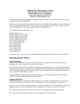
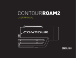
Shapes version 1.0
Users Manual for
Windows, Macintosh
and Unix Platforms
September 2000
Table of Contents
Toolbar Menus
File
Saving and Loading
Edit
Features
Help
3
4
4
6
Object Editing
Editing from the Main Modeling Window
Shape
Color
Polygon Mode
Editing from the Object Edit Box
Sliders
Shading
Outlines
Copy Menu
Link Menu
9
10
10
10
11
Global Editing
Sliders
Background Color
All Object polygon modes
All Object shading modes
13
13
13
14
Animation
15
Shapes 1.0 users manual
7
8
8
2
Toolbar Menus
The Toolbar consists of five options:
1. The File menu allows you to open, save, and print* your work, or quit the application.
2. The Edit Menu is used to manipulate the workspace and reset data.
3. The Features Menu adjusts the actual representation of the objects.
4. The Help Button turns on the floating online guide.
5. The About Button displays information about the current version of Shapes.
File Menu
The file options are Open, Save, Print*, and Quit.
Saving
You can save your work and reload it at a different time. To save your work, hit the Save
button in the file menu. You will be asked what to name the file. You may enter up to 12
characters for the filename. If the file already exists, you will be asked if you wish to
overwrite the file. The new file will be placed in the same directory as the Shapes
application, and will consist of all of the current modeling data and all of the current
animation data. (for more on animation, see Page 15)
When you want to open up your saved file, there are two requirements. (1) The file must be in the same directory as the Shapes application. (2) You must know the filename of the file you wish to open. Once these two
requirements are met, press the Open button in the file menu. Then enter in the name of the file. If the
filename requested cannot be found or opened, an error message will display. Otherwise, you will be presented
with an option to load the Model in the file, the Animation information, or both. In most cases, you would
likely want to load both the model and animation.
Print (Windows and Unix only)
You can export the current 3d display window into a postscript printer file by pressing the Print button in the
File menu. The postscript file will be created as “shapes###.ps” where ### represents a number starting from 0
and incrementing every time Print is pressed. The application will report the completion of the file and output
the filename to the screen. The postscript file can be run through a postscript reader such as Adobe Acrobat
Distiller or Ghostscript to view and print the file.
Printing at SDSC
When using the program at the San Diego Supercomputer Center, the postscript file will automatically be sent
to the color printer “Prism” when the Print button is hit. Please check with an appropriate representative to pick
up your print, and please do not hit Print more than once for each image to be printed.
Quitting the application
To exit shapes, hit the Quit button in the File menu or hit the Escape key on the keyboard. A dialog box will
appear asking to confirm that you wish to quit the program.
*printing is available on the Windows and Irix platforms only.
Shapes 1.0 users manual
3
Toolbar Menus
Edit Menu
The edit options are Show Selections, Mouse Zoom, Reset Models, and
Reset Animation.
Show Selections
This feature is on by default, and highlights a particular shape being worked on
with a wireframe bounding box around the shape. This helps identify which object
is being worked on when multiple objects exist in a scene. Clicking the Show Selections button in the Edit
menu will toggle this feature on or off. This feature can also be toggled using the “Show/Hide Outlines” box in
the Object Edit box. (see Page 4: Show Selections)
Selections Hidden
Selections Shown
Mouse Zoom
By default, the left mouse button rotates the 3d scene, while the middle mouse button zooms in and out of the
scene. By turning on Mouse Zoom in the Edit menu, the left button will become the zoom button and the
middle button will rotate the scene. This feature allows for the full range of viewing using one-button mice,
such as on the Macintosh platform. Alternatively, the “r” key on the keyboard will restore the left mouse button
to the rotate function and the “s” key will restore the mouse button to the zoom function.
Reset Models/Animation
The Reset Models button restores all the default values for the modeling palette. This does not clear any data in
the animation palette. The Reset Animation button only appears if the Animation palette is active, and clears all
data in the animation palette but leaves the modeling palette intact.
Features Menu
The features menu options are Axes On, Perspective On, Thick Wires, Hi-Res
Mode, and Animation.
Axes
By turning on the axes, you can get a better view of the placement of the models
in relation to the 3d space. The X, Y, and Z axes are placed in the positive
direction from the center. Axes can be toggled on or off using the Axes On
button in the Features menu.
*printing is available on the Windows and Irix platforms only.
Shapes 1.0 users manual
4
Toolbar Menus
Perspective Off
Perspective On
Perspective
On by default, Perspective toggles on and off with the Perspective button in the Features menu. When perspective is off, the projection is set to orthographic. The difference: when perspective is on, objects that are farther
away appear smaller towards the horizon. Having perspective on gives a representation more accurate to what
our eyes see.
Hi-Res Mode
Shapes that appear to be round consist of multiple facets that form the structure of the object. The greater the
number of facets that make up a round object, the smoother it looks. However, the more facets that an object
has, the longer it takes for the computer to draw it to the screen. Hi-Res mode is a mode that allows you to
work with more facets for each polygonal shape, improving object appearance. By default, Hi-Res mode is off
in order to maximize computer performance.
Below are examples of the same spherical object with Hi-Res mode off and Hi-Res mode on. Notice the number of patches in each mode.
Hi-Res Mode Off
Hi-Res Mode On
Animation
An advanced feature, Animation allows you to generate two sets of models and have them morph between each
other. This is off by default and is covered more extensively on Page 15.
Shapes 1.0 users manual
5
Toolbar Menus
Help Menu
The Help Menu button turns the floating Help Menu on or off. The Help Menu will
change based on the options being chosen by the user. For example, in the main window, the Help Menu has options for each of the main tools: File, Edit, and Features,
along with help information for the Object items. If Animation is on, an Animation
option appears in the Help Menu as well. If the user is editing an object’s color, the Help
Menu changes to just an option for the Color Menu.
Clicking on one of the Help Menu choices brings up a set of overlays that describe the
feature or features and the usage. In the figure below, the Objects option is selected in
the main window, describing the various features of how to manipulate objects from the
main screen.
Shapes 1.0 users manual
6
Object Editing
Up to 20 objects can be created to produce one set of models. Each object has its own color, shape, polygon
mode, and location and orientation settings which can be independent of the other objects in the scene. These
objects can be manipulated from the main object palette as well as from an object edit menu that can be accessed
from the main object palette.
When starting the Shapes program, only object # 1 is active and objects 2 through 20 are off. Every object is a
white sphere by default.
Editing from the Main Object Palette
Turning objects on and off
Clicking the number of the object turns it on or off. When the object is on, the button with the object number is
white and all of the buttons on that row are available. When an object is off, the object button is grayed out and
the remaining buttons for that object are grayed out and unavailable.
Editing the Primitive Shape of an Object
The second button in an object’s row of buttons describes the primitive shape of the object, which can be one of
Sphere, Cube, Cone, or Cylinder. Clicking the shape name brings up a dialog box showing the available shape
types. A yellow box is drawn around the name of the currently chosen shape. If Show Selections is active, a
wireframe highlight is drawn around the object in the 3d scene. Click Done when satisfied with the new shape,
or Cancel to revert to the last confirmed shape.
Shapes 1.0 users manual
7
Object Editing
Editing the Color of the Object
The third button in an object’s button row appears in the color of the object’s material properties. To edit the
color of the object, click the button and choose a new color from the available colors. A yellow box is drawn
around the currently chosen color if the current color appears in the color menu. If Show Selections is active, a
wireframe highlight of the same color of the object is drawn around the object in the 3d scene.
Transparency of an object can also be set in the Color menu. The more transparent an object is, the more you
can see through it, like glass. By default, transparency is set to zero, making the object appear completely solid.
Moving the transparency slider to the right makes it more transparent. A completely transparent object appears
practically invisible.
Click Done when satisfied with the new color and transparency settings, or Cancel to revert to the last confirmed settings.
Color Menu
Transparency Example
Editing the Polygon Mode
Each object has a polygon mode. The mode is set to polygons by default, meaning the object appears to be a set
of solid surfaces. The other main mode is wireframe, where the construction framework of the object is shown
as a wire mesh. Two wireframe modes are available, the first being a set of wires in low resolution mode while
the second wireframe mode is a wireframe set in high resolution mode. Wireframe modes are unaffected when
toggling the Hi-Res Mode option on or off in the features menu, and are controlled instead by setting the polygon mode of the object. Cubes only have one wireframe type available.
Wireframe1 (Lo-Res)
Shapes 1.0 users manual
Wireframe2 (Hi-Res)
8
Object Editing
Editing from the Object Editing Palette
Accessing the Object Editing Palette
To turn on the object editing palette, click the Edit button on
the button row of the object you wish to edit. Then the editing palette will appear in
front of the main object palette. Several editing features will now be available.
Sliders
Positioning the Object
The object can be positioned relative to the X, Y, and Z axes by using the position
sliders for each axis. Sliding to the right moves the object along the chosen axis in the
positive direction, while sliding to the left moves the object along the axis in the
negative direction.
Note: Spheres and Cubes have their position defined from the center of the object,
while cone and cylinder positions are defined at the base of the object.
Rotating the Object
Each object can be rotated along the three major axes as well. The rotation sliders
range from -180 degrees to 180 degrees. Rotations occur in the following order:
rotation about the x-axis, rotation about the y-axis, then rotation about the z-axis. Note
that rotations are made about the center of the object’s spatial location.
Object Scale
The default shape of an object can be manipulated using the Object Scale sliders. These define the multiplication of the object’s dimensions along each of the three major axes and are independent of each other. Please
note that object scale is considered before the rotation of the object.
Object Attributes
Each object type has a particular set of attributes that can be adjusted. Cubes and Spheres have a uniform radius
that can be manipulated, while Cones and Cylinders have base radius and height length that can be adjusted.
These Object Attributes are multiplied by the Object Scale sliders to create the object’s final dimensions.
Shapes 1.0 users manual
9
Object Editing
Other Object Editing Features
Shading
Each rounded type of object (sphere, cone, cylinder) is composed of a number of facets that make up a round
face. When smooth shading is not enabled, these facets are displayed as flat surfaces. When smooth shading is
on, the facets are lit as if the object were round. This is easier to see than to explain. Notice the mode settings
below and the difference that smooth shading makes, however the edges of the facets are still noticeable when
there are few facets.
Smooth Shading Off
Smooth Shading On
Show/Hide Outlines
This is the same feature that is toggleable from the Edit Menu, and turns on/off the wireframe object highlight
that surrounds the current object being worked on.
Copy Menu
This feature allows an object to copy all of the attributes that another object has. For example, say you want to
build two wheels of the exact same size and dimension, to place on a car. You could first build one cylinder and
mold it to the desired shape. Then you could duplicate it and move the duplicate to the other side of the vehicle.
Duplicating an object copies the original object’s shape type, color, polygon mode, xyz position, xyz rotation,
xyz scale, object shape attributes, and shading.
To use this feature, first click on “Copy Menu” in the Object Edit Box window. A listing of 20 objects show up,
but some are grayed out and unselectable. The remaining object numbers are colored according to the object
colors in order to assist in locating the desired original object to copy. Clicking on an object will select it to be
the desired original object. The target original is highlighted in blue and the current object is highlighted in
white. Clicking “Copy” will finalize the duplication. The current object will duplicate the original object’s
attributes and occupy the same space as the target original.
Shapes 1.0 users manual
10
Object Editing
Copy Menu Example
In the above diagram, Object #9, the orange sphere, is the object that will be copied. Note the blue highlight
designating it as the target to copy from. Object #1, which is currently a white cube, is the target to copy into,
which is highlighted in white.
Several objects may be grayed out and uncopyable for the following reasons.
1. You can only copy an active object.
2. You cannot make an object copy itself.
Advanced Feature: Link Menu
All objects are placed and rotated about their center point. However, if multiple objects need to rotate together,
like a head with a hat on it, there is no grouping feature. Instead, we create hierarchical link structures. First
click on the “Link Menu” button in the Object Edit Box window. A similar window to the Copy Menu appears.
Several objects may be grayed out and unlinkable for the following reasons.
1. You can only link to active objects.
2. You cannot link an object to itself.
3. You cannot link an object to any object hierarchy that includes itself. (i.e. 1 links to 5, 5 links to 7. 7 cannot
link back to 1 or 5.)
Shapes 1.0 users manual
11
Object Editing
Original Scene
Object 1 linked to Object 8
Object 1 linked to Object 7
An object that is linked to another object does not use the default axes (located at 0,0,0) as a reference point.
Rather, if object a links to object b, then object b’s position and rotation settings create a new set of axes for
object a to use as xyz position 0,0,0. This is more confusing in words than in pictures. Note the diagrams
above. The first image shows the basic scene we are working with. Object #1 is the white cube in the center of
the screen. We then link to the green cylinder. The green cylinder is then highlighted in blue, with a new set of
blue axes created to show the new reference point axes. The third diagram shows where the white cube would
be placed along with the new set of axes when the cube links to the orange sphere instead. The blue axes will
always show the relative reference point of the current object.
Shapes 1.0 users manual
12
Global Editing
Global Scene Editing
All of the objects in the entire scene can be manipulated in a number of ways.
This feature groups all objects together and operates on them as a single group.
This can be used to approximate a better view of the objects or to view the scene
in a different manner. To use Global scene Editing, click on the Global Scene
Edit button located a the bottom of the main modeling panel window.
Sliders
Position, rotation, and scale can all be set globally in the Global Scene Edit menu,
affecting all objects.
Background Color
The color of the background (default being black) can be set in the Global Scene
Edit menu by clicking on the current background color box. Background color
can be set similarly to how object colors are set, except that there is no transparency feature in the background color menu.
All Scene Polygons
Overrides polygon settings for all polygon shapes to Polygon, Wire1, or Wire2. Polygon will act as if all objects
are set to “Polygon” for polygon mode. Wire1 acts as if all objects are set to “Wireframe1” for polygon mode,
which uses low resolution (fewer) wires. Wire2 acts as if all objects are set to “Wireframe2” for polygon mode,
which uses high resolution (more) wires.
To use, first turn on All Scene Polys in the Global Scene Edit menu. This will turn on which polygon settings
you want to apply. Click on the polygon setting button to cycle through the options. Clicking on All Scene
Polys again will turn the feature off and restore individual object polygon settings.
All Scene Polys set to Wire1
Shapes 1.0 users manual
13
Global Editing
All Scene Shading
Overrides shading settings for all polygon shapes to either Smooth or Facet. If Smooth is selected, the scene
appears as if all objects have Smooth Shading turned on in the Object Edit Box Menu. If Facet is selected, the
scene appears as if all objects have Smooth Shading turned off in the Object Edit Box Menu.
To use, first turn on All Scene Shading in the Global Scene Edit menu. This will turn on which shading settings
you want to apply. Click on the shading setting button to toggle between the options. Clicking on All Scene
Shading again will turn the feature off and restore individual object shading settings.
All Scene Shading set to Facet
Shapes 1.0 users manual
14
Animation
You can record two frames and/or camera angles and animate between them. To use this feature, Animation
must be active in the Features Menu.
Animation Types
You can animate between different camera angles or different frames in any combination. This means your
animation can consist of:
Two camera angles and two frames of animation
One camera angle with two frames of animation
Two camera angles with one frame of models
An animation must have at least two camera angles or two frames active. To activate a frame or camera angle,
click on the button that states the name of the frame, i.e. “Frame1 Off”.
Animating Frames
A frame is the state of all 20 Objects, including the Global attributes. In the animation panel, you first have to
turn on the frame you wish to be active. Find a model set you like, then hit the Record button next to the
frame’s name. Restore loads back the frame that you recorded there. When you have two frames, you can play
the animation between them by hitting the Play button.
Animating Camera Angles
A camera angle is defined by the current rotation and zoom viewpoint. In the animation panel, you first have to
turn on the camera you wish to be active. Find a camera angle view that you like, then hit the Record button
next to the camera angle’s name. Restore loads back the angle that you recorded there. When you have two
camera angles, you can play the animation between them by hitting the Play button.
Looping
Animations can be played in forward order, reverse order, or looped. Looped animation allows for the animation to repeat in forward order (Fwd-Fwd), reverse order (Rvs-Rvs), or alternating back and forth between them
(Fwd-Rvs). Click on the Loop:... button next to the Rvs button to turn on the Loop setting. Click on the Loop
button again to change the Loop setting. Click Play to watch the loop, then click Stop when finished. Clicking
on the Fwd or Rvs buttons will deactivate the Looping.
Shapes 1.0 users manual
15