1
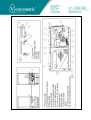
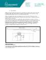
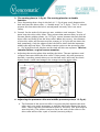
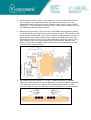
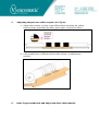
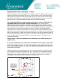
Mechanic manual Manure Belt System.
First of all, the mechanic must be fully informed about the User Manual.
Installation:
1.
Check the delivered drive and return units.
a. The drive unit (fig A): Are all parts mounted? Can you move the
bearing plates (no 8 fig A) freely, is there enough clearance on the
lock nuts? (n° 6+7 fig A) Can you move the side plate at the nonmotor side and is the motor side bolts all tight?
b. The return station (fig B): Are all parts mounted? Will the cage roller
(n°1 fig B) remove the dirt when you rotate it in the right direction? If
not, swap the cage roller end for end. The auger flighting inside
should move material to the outside edges where it will fall out of the
system.
2. Welding the belts, adjusting the Return Unit (R.U) and the Tension Unit
(T.U.) in the Drive Unit (D.U.)
a. Welding a belt.
Take care! When you weld a belt, keep the cage roller roughly in the middle of the
adjusting range.( fig B) Otherwise there is not enough space for the small scrapers
(n° 2 fig B) that are in front of the cage roller. Take care, the belts will shrink and
grow in length depending on the temperature and the length of the house.
Remind that a belt will shrink when it is getting colder in the house. Be sure to
mount the small belt plates (art.n°. 276185 of 3000200621) and bend them a little
by hand. This will prevent cutting the belt.
b. The welding:
When you loop the belt through the T.U. and the D.U. hold it tight. Take care! The
position of the cage roller must be roughly in the middle of the adjusting range.
The extension springs in the T.U. are not stretched now.
When overlapping the belts for welding, put the of the belt coming out of the
terrace sections as the bottom belt. Remove any sharp edges so nothing can hook
when the belt is running.
Put the other piece over the “section part” and overlap them 3 meters. (10 feet).
Keep both belts aligned and square with each other-this is very important! Keep the
joint above the turning plate. (n° 2 fig A) You can weld here with a sonic welder
without using an extra piece of sheet metal or wood for backing.. Tack weld the
belts with a few welds. Keep the overlap 7 cm.(3”) for 2.0 mtr. (78 “) and 2.3
mtr.(90”) type systems. For 1.15mtr. (45”) and 1.7 mtr. (67”) units 5cm. (2.5”)
overlap is enough. After welding, cut off the excess.
.
Imported things;
Keep both parts aligned.
The temperature of the house and belts must be 15°C (59°F) or higher. So, don’t
store the belts outside. After welding don’t run the belts for 4 to 6 hours. The welds
must crystallize (cure)
c. Adjusting the R.U. (preload of the belt)
How tight must the belt be adjusted? Often they are too tight. Remember this is
not a conveyor belt – drive comes from the pressure system in the drive unit, NOT
from overall belt tension! A new belt (not running and without manure) is adjusted
when the spring tension roller (n° 10 fig A) in the T.U is somewhere in the middle
of the slot. ( fig. 2 and 3) When the belt runs for the first time it will stretch a little.
After this first run the tension (slack adjustment) must be checked. (and adjusted, if
necessary)
fig 1
d. Check the adjustment of the T.U.
The scraper on the tension roller is factory set, but please double check this. Also
check the tension of the springs, they must be the same on both sides. See the
screw eyes.
fig2
fig3
3. The turning plate (n° 2 fig A). The turning plate has a double
function.
a. First: Preventing that a loop in the belt (n° 11 fig A) gets stuck between the
belt itself and the drive roller – a “double wrap”. (n° 3 fig A). The T.U. should
prevent this but when the belt is not adjusted correctly, this is an extra
safety.
b. Second: On the ends of this part are two, stainless steel scrapers. These
parts keep the drive roller clean. They prevent that manure what, in spite of
the two plastic guiding plates, (nr 12 fig A) comes between the belt and the
drive roller can build up on the drive roller. When this occurs, the diameter
of the drive roller will increase and the scraper (n° 4 fig A) will not clean the
belt completely. Only the edges of the belt will be clean and the important
middle part will stay dirty. The rubber traction strips on the pressure roller
(n° 1 fig A) will loose all traction and the belt will not run anymore. This is a
common failure, so give it extra attention.
c. Adjusting the turning plate after welding the belts. The two stainless steel
scrapers must not touch the drive roller. If they touch, this will generate a
horrible, squealing sound when you run the belt and it will scare the birds.
Always keep a small gap between the scrapers and the drive roller.
4. Adjusting the pressure roller and middle pressure point(n° 13 fig A).
a. The function of the pressure roller is to press the belt against the drive
roller and, even more important, to pull the belt firmly around the drive
roller. That’s why the circumference speed is 4% more. This also helps to
steer the belt. (The rubber cams are not at the ends of the roller so the
drive roller will act like a pair of conical (convex) pulleys)
b. If the pressure roller is dirty ( wet manure), it will not function correctly,
the traction is lost and the belt will slip and stall, therefore it is very
important to keep this roller and its rubber traction strips clean. Small
scrapers (n° 5 fig A) keep the traction strips clean. After running the belt
this should be checked and cleaned.
c. Adjusting the pressure: The pressure is adjustable through three points:
a red spring at each edge and a center pressure block. The tension must
be the same at both ends so it is best to build up the pressure evenly, so
adjust both sides evenly, step by step. When you tighten first one side
and than the other side the risk of an outbalance pressure roller is very
high. Always check the gap between the bearing plates and the side
plates. (In the latest models small center points are punched in to help
as a reference measurement)
d. The middle pressure point (n° 13 fig A) (when delivered) is already
adjusted in the factory but can be adjusted if necessary. When adjusting
or re-adjusting this device, always be sure that the pressure on the
pressure roller is even on both ends and the position is, as described in
5.
Adjusting the pressure roller scrapers (n°5 fig A):
a. Adjust the scrapers as close as possible without touching the rubber
traction strips, especially the older, glued types of pressure rollers.
b. Later models have a different device with springs, no adjustment
needed.
6.
Don’t forget to lubricate and adjust the drive chain tension.
Explanation the customer / user:
Start by making it clear that the Manure belt drive system is not a typical conveyor
belt and should not be treated like one. A conveyor belt is often equipped with a
rubber belt and this will act like a big rubber band. A conveyor belt needs a high
preload to work. When this conveyor belt stalls, the preload must be increased at
the return side. The traction will be more and the belt will run again.
This is the big difference with a manure belt drive system. The PP belt is
not rubber but acts more like a sheet metal plate. The preload (slack
adjustment) should be as little as possible, just enough to cope with the stretch
when running the belt. When the belt stalls, increasing the preload will not work.
The cage roller and the rollers in the T.U. will bend (and probably be damaged) and
the resistance to the belt running will increase. The forces on the belt will be
tremendous. Since the force on the belt is concentrated on the middle part of the
belt, (where the rubber traction strips are mounted) the material in the middle part
will be overstretched. At both ends this will not appear so the belt deforms and the
only way the stretched material can go is upwards. If you overstretch the belt even
more, the belt will run start to pull to the center and overlap. This belt is now
permantly damaged.
Always refer to the User Manual to the customer/user while doing your
explanations.
In this User Manual steering, tensioning and maintenance are clearly described but
explain him again that he can only move the carriage on the non-motor side. The
motor side is locked in place. (In case of an emergency Vencomatic personnel can
remove this blockage and steer on this side. Always check the tension of the drive
chain when you do this)
Tell the customer/ user that in particular when steering the belt a side plate will
move towards him when he tightens the nut, but will not go backwards when he
loosens the nut. When he runs the belt, after adjusting, the side plate will move
backwards most of the time (because of the force on the belt) but not always.
Sometimes he must help it with a crowbar or similar tool.
What to do when a belt stalls (and what not to do!):
When a belt stalls never increase the preload at the slack adjuster. When the belt
ran okay before, find out why it stalls now. Possible causes:
•
Too much manure on the belt. Too much weight. Too wet because of a
leaking drinking system, poor ventilation in colder seasons. It is also possible
the manure level is too high and drags on the slat bars. The resistance will
be very high.
•
The rods that support the returning (lower) belt are very dirty. Dried manure
builds up and squeezes the belt between the dry manure and the tubes
supporting the top belt. This happens often when the scrapers are not
cleaned and the belt is dirty.
•
One or both rollers in the T.U. is damaged or is out of round.
•
The cage roller is damaged or will not rotate anymore. Check why!
•
Are the keys present in the keyways from the grey plastic sprockets?
•
Temperature dropped, the belts have shrunk, but no slack adjustment to
reduce the belt tension has been made.
•
The scraper does not clean the belt.
•
Another cause, something is holding the belt back.
When you checked everything and did not find a cause, you may increase the
tension of the pressure roller. (the red compression springs) Reminder: keep the
tension on both sides even. When a middle pressure point is installed you may
increase the pressure a little. Never increase the pressures more than
necessary.
Instruct the customer again to decrease the tension at the R.U. when the
birds go out of the house and the belts will shrink. This is easy to forget!
Anthony Bal
Mechanical Engineer
Vencomatic, The Netherlands
©2008 Vencomatic b.v.
Short Checklist Drive Unit Manure Belts.
Remark: This is just a short checklist. For more information, read the manual.
Starting the drive units:
1. Safety first. Does everybody knows you want to start the drive units and cross
conveyor(s)
2. Tension the scrapers (are they clean??)
3. Run the belts and…..
4. Check the distance left and right. If adjusting is needed only adjust the side where
no moter is mounted. (because of the tension of the chaine) Adjusting always when
the drive unit is not running. One half turn at the time.
5. Check the position of the belt tension unit (tensionroller should be in the middle
of the groove)
6. Keep looking at the belts all times. A damaged belt can cause problems with the
scrapers.
7. Check the return stations. (are the belts in the middle)
After running the belts:
1. Safety first. Start cleaning when all systems are shut down.
2. Release the scrapers and keep them released.
3. Clean the scrapers, in particular the back side of the pur strip.
4. Clean the rest of the unit (don’t forget the pressure rollers)
5. Check and clean the return stations.
Don’t forget when the house is going empty
Always take care that at the moment the chickens are out of the house, the return
stations of all manure belt systems and also the return stations of the egg-belt has to be
put back in the lowest tension positioning.
When the birds are going out of the house, the temperature will drop and the belts will
shrink.
If you don’t release the return-stations to get off all tension of the belts, a lot of damage
can be done on the belt itself, cage-rollers etc.. because the basic-material PP react
enormous on temperature. As example, 10° C / 18° F. lower / reducing in a house of
100 mtr. / 109 yd. length will give a shrinkage of 35 cm./ 1 ft. of the belt.