1
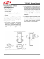
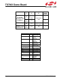
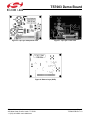
TS7003 Demo Board Evaluation with TS7003 Demo Board Only Required Equipment TS7003 Demo Board DC Power Supply Low-noise Signal Generator Stanford Research Systems Model DS360 or better w/ BNC cable Ammeter In order to evaluate the TS7003 using the TS7003 demo board only, additional input signals for the തതതത CS SCLK and തതതതതതതതത SHDN pins will be necessary along with an oscilloscope to monitor the inputs and output. The following steps are to be performed: 2) Timing signals for the TS7003 input signals AIN, തതതത SHDN, and SCLK should be set according to CS, തതതതതതതതത the desired measurement based while following the product datasheet specifications. Refer to the TS7003 product datasheet “Description of Operation” for details. Access to these pins is available through the 34-pin header, X1, labeled തതതതതതതതത, and DOUT. The as SCLK, തതതത CS, SHDN corresponding pins on X1 are 10, 8, 4, and 6, respectively. 3) To measure the supply current of the TS7003, place jumper J2 to position 2-3. Then, apply an external power supply to J1. An ammeter can now be connected in series with the power supply for a supply current measurement of the TS7003. The supply current should be approximately 950µA. Please refer to Figure 5 and table 1. 1) Set the voltage of the power supply between +2.7V and +3.6V and turn it off. Connect the positive terminal of the DC power supply to pin 12 labeled as 3.3V on the 34-pin header, X1, and the ground terminal to pin 2 labeled as GND. Refer to Figure 5. Figure 5. TS7003 Evaluation Board Circuit TS7003-EVB Rev. 1.0 Page 5