1
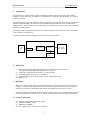
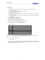
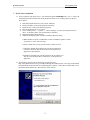
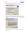
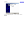
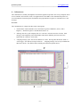
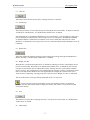
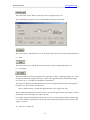
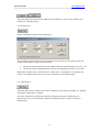
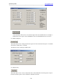
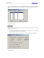
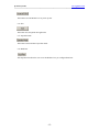
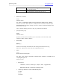
CANmunicator User Manual
QuickCAN interface program
Revision 1.8
Date: 04-01-2008
1.
Introduction ------------------------------------------------------------------------------------------------------------1
2.
Quick Start--------------------------------------------------------------------------------------------------------------1
3.
Disclaimer---------------------------------------------------------------------------------------------------------------1
4.
System requirements--------------------------------------------------------------------------------------------------1
5.
Specification ------------------------------------------------------------------------------------------------------------2
6.
QuickCAN hardware pin-out and LED indication -------------------------------------------------------------2
7.
Device driver installation --------------------------------------------------------------------------------------------3
8.
CANmunicator ---------------------------------------------------------------------------------------------------------6
9.
8.1.
Clear All ----------------------------------------------------------------------------------------------------------7
8.2.
Get Message ------------------------------------------------------------------------------------------------------7
8.3.
Enable Scan ------------------------------------------------------------------------------------------------------7
8.4.
Display live data -------------------------------------------------------------------------------------------------7
8.5.
Save----------------------------------------------------------------------------------------------------------------7
8.6.
Add message------------------------------------------------------------------------------------------------------7
8.7.
Send----------------------------------------------------------------------------------------------------------------8
8.8.
Arm Trigger ------------------------------------------------------------------------------------------------------8
8.9.
Abort Tx ws Enable Tx-----------------------------------------------------------------------------------------8
8.10.
Periodic Send-----------------------------------------------------------------------------------------------------9
8.11.
Filter Registers ---------------------------------------------------------------------------------------------------9
8.12.
Baud rate Register --------------------------------------------------------------------------------------------- 10
8.13.
Register map---------------------------------------------------------------------------------------------------- 10
8.14.
MCP2515 Status ----------------------------------------------------------------------------------------------- 11
8.15.
Reset MCP2515 ------------------------------------------------------------------------------------------------ 11
8.16.
Exit--------------------------------------------------------------------------------------------------------------- 12
8.17.
Operation mode ------------------------------------------------------------------------------------------------ 12
8.18.
Baud Rate ------------------------------------------------------------------------------------------------------- 12
USB-2-CAN Communication protocol -------------------------------------------------------------------------- 13
9.1.
Command R----------------------------------------------------------------------------------------------------- 13
9.2.
Command W ---------------------------------------------------------------------------------------------------- 14
9.3.
Command C: --------------------------------------------------------------------------------------------------- 14
9.4.
Command X----------------------------------------------------------------------------------------------------- 15
9.5.
Command I ----------------------------------------------------------------------------------------------------- 16
9.6.
Command A:---------------------------------------------------------------------------------------------------- 16
9.7.
Command T:---------------------------------------------------------------------------------------------------- 17
9.8.
Command M: --------------------------------------------------------------------------------------------------- 17
9.9.
Command D: --------------------------------------------------------------------------------------------------- 18
9.10.
Command Q: --------------------------------------------------------------------------------------------------- 18
9.11.
Command V:---------------------------------------------------------------------------------------------------- 19
9.12.
Command Z:---------------------------------------------------------------------------------------------------- 19
9.13.
Command ‘G’ -------------------------------------------------------------------------------------------------- 20
9.14.
Command ‘K’ -------------------------------------------------------------------------------------------------- 21
9.15.
Command ‘B’--------------------------------------------------------------------------------------------------- 21
9.16.
Command ‘H’ -------------------------------------------------------------------------------------------------- 22
9.17.
Command J: ---------------------------------------------------------------------------------------------------- 22
10.
Initialization ---------------------------------------------------------------------------------------------------------- 24
11.
Revision History ----------------------------------------------------------------------------------------------------- 27
Q-Proto Systems
www.qprotos.com
---------------------------------------------------------------------------------------------------------------------------------
1. Introduction
QuickCAN device provides a simple, reliable and high-performance connection between your PC and the
controller area network (CAN) via USB port. No external power is required as QuickCAN device is powered
by built-in USB port.
QuickCAN package comes with a Windows interface application program called CANmunicator. This program
initializes QuickCAN MCP2515 firmware at startup, and provides point and click access to all MCP2515
internal registers. It also provides a user-friendly interface to send and receive CAN messages that can be either
standard or extended frames.
QuickCAN package also provides the USB-2-CAN communication protocol, which offers users the flexibility
to develop their own applications.
The following block diagram illustrates the operation of the QuickCAN device.
QuickCAN device
PC
USB
Port
USB
C8051F320
Core
MCP2515
Controller
Area Network
16 MHz
Clock
2. Quick Start
2.1. Download QuickCAN Application (QuickCAN.exe) from Q-Proto system web site
www.qprotos.com/download.html and install it to your local.
2.2. Connect the QuickCAN device to the PC via USB A-B cable.
2.3. Install the Windows device driver (see chapter 6).
2.4. Launch the QuickCAN.exe from Windows <start>-<QuickCAN> menu.
2.5. Ready to use.
3. Disclaimer
While every effort has been made to ensure that the information contained in this manual is accurate and
complete, no liability can be accepted for any error and omission. Q-Proto system reserves the right to
change the specification of the hardware and software described herein at any time prior notice.
Q-Proto System shall not be liable for direct, indirect, incidental, general or consequential damage from the
use of the products from Q-Proto system. If you do not agree with these terms, do not buy the products.
4. System requirements
4.1.
4.2.
4.3.
4.4.
Windows 98SE, 2000, XP operating system
Pentium II 350MHz or above
Minimum 256M RAM
One available USB 1.1 or above port on the PC
-1-
Q-Proto Systems
www.qprotos.com
---------------------------------------------------------------------------------------------------------------------------------
5. Specification
5.1.
5.2.
5.3.
5.4.
5.5.
5.6.
High speed 8051 compatible microcontroller C8051F320 with built in USB functionality.
CAN2.0A and B support.
Microchip MCP2515 CAN controller running at 16 MHz.
Microchip MCP2551 CAN transceiver.
Self powered by USB port.
The CANmunicator initializes the MCP 2515 firmware at start up. The device is ready to send and
receive CAN messages.
5.7. Documented USB to CAN communication protocol allows users to develop their own applications for
extensive usage.
5.8. Full USB1.1 speed at 12MHz.
5.9. DB9 Male connector for CAN network.
5.10. Support loopback and listen operations.
5.11. Up to 1 M bit software selectable CAN baud rate.
5.12. Windows driver for Win98 SE, 2000 and XP is included.
6. QuickCAN hardware pin-out and LED indication
6.1. DB9 Male pin-out
Pin 1
Pin 2
Pin 3
Pin 4
Pin 5
Pin 6
Pin 7
Pin 8
Pin 9
RST (Not used for CAN bus. Do not connect this pin)
CAN Low
GND
C2D (Not used for CAN bus. Do not connect this pin)
Shield GND
GND
CAN High
C2CK (Not used for CAN bus. Do not connect this pin)
N/A
Pin 1, Pin 4 and Pin 8 are used for C8051F320 programming purpose and they shall not be used for CAN
connection. Misuse of these pins may result in damage of the QuickCAN device.
Pin 9 (V++) is not connected at this time.
6.2. LED indication
The LED performs prove-out sequence: ON->OFF->ON when the QuickCAN device is connected to the
PC. The lit LED indicates that the device is powered. Please note that the Windows device driver must be
installed before the QuickCAN is ready to be used.
-2-
Q-Proto Systems
www.qprotos.com
---------------------------------------------------------------------------------------------------------------------------------
7. Device driver installation
7.1. For new purchase, skip to the step 6.2. For Interface Program UPGRADE from 1.0 to 1.1 or later, the
following steps must be followed to ensure the QuickCAN device is working properly on the new
device driver.
1)
2)
3)
4)
5)
Detach the QuickCAN device from your PC USB port.
Remove the older version of the QuickCAN directory.
Install the new version of the Interface program.
Plug the QuickCAN device to your PC
Go to <Control panel> -> <system> -> <device manager> to remove the QuickCAN device
driver. It should be under <Universal Serial bus controller>.
6) Detach and reattach the QuickCAN.
7) Windows should pop up the <Found new hardware Wizard> dialog.
a) When Windows OS asks "Can Windows connect to Windows Update to search
for software?", Click <this time only>.
b) Select "install from a list or specific location" and click <next>.
c) Check the "include this location in the search" box and browse
to the driver directory that the driver directory that QuickCAN
application is just installed.
d) Sometimes, Windows may ask the location of the file "SiF32x.sys".
This file is also under the driver sub directory of the QuickCAN
application.
7.2. The following steps are only applied to the new purchase user.
Plug in the QuickCAN device to your USB port through the USB A-B cable. The setup wizard should
run automatically and a Welcome screen should appear as follows. Select option <Install from a list or
specified location (Advanced)>. Then click the <Next> button.
-3-
Q-Proto Systems
www.qprotos.com
--------------------------------------------------------------------------------------------------------------------------------7.3. Select option <Search for the best driver in these locations>. Set the search location to the directory
where QuickCAN driver is located, i.e. c:\QuickCAN\driver if you unzip QuickCAN.zip to
c:\QuickCAN. Then click the <Next> button.
7.4. Occasionally, you may get the following warning on some operating systems. This is because
QuickCAN device driver has not been certified from Microsoft at this time. However, this installation
should not effect the operation of your system. Click the <Continues Anyway> button to continue
installation.
7.5. Click the <Finish> button to complete the installation after the hardware wizard finishes installing
QuickCAN device driver.
-4-
Q-Proto Systems
www.qprotos.com
---------------------------------------------------------------------------------------------------------------------------------
To verify the successfully installation of the driver, open Windows <control panel> Æ <System> Æ
<Hardware> Æ <Device Manager>, the QuickCAN device shall be shown under “Universal Serial Bus
controllers” tree.
-5-
Q-Proto Systems
www.qprotos.com
---------------------------------------------------------------------------------------------------------------------------------
8. CANmunicator
The CANmunicator (formally called QuickCAN interface application) provides users an easy and quick start to
access Controller Area Network (CAN). The application uses the USB-2-CAN communication protocol to
access the MCP2515 internal registers and initialize the proper MCP2515 registers to send and receive CAN
messages.
Overview:
The CANmunicator is composed of three major control groups.
1.
Action buttons: Send command to access the internal registers of MCP2515, such as <Filter
Registers>, <Baud rate registers> and <MCP2515 status> etc.
2.
<Message Activities> pane: Displays both <Tx> and <Rx> activities across the CAN bus. Each
message is time stamped by either the Windows timer that is defined by the Timer interval in
QuickCAN.ini or firmware 16 bits timer.
3.
<Outgoing message> pane: Lists all user-defined <Tx> data. Pressing either the button <Send> or
<Arm Trigger> can send any messages in this list. <Outgoing message> list can be pre-loaded with
data from a flat file. The data file name with full path is defined in QuickCAN.ini.
-6-
Q-Proto Systems
www.qprotos.com
--------------------------------------------------------------------------------------------------------------------------------8.1. Clear All
This button removes all the activities in the <Message Activities> control list.
8.2. Get Message
This button gets all the received CAN message from the QuickCAN software FIFO. It cannot be used with
<Enable Scan> simultaneously. It is disabled when <Enable Scan> is enabled.
The QuickCAN device uses Interrupt Method to receive CAN messages. User must make sure the receive
bits in CANINTE are enabled before CAN messages can be received properly. Both RX1IE and RX0IE
are enabled when the CANmunicator is launched. Users must re-enable those 2 bits after the <Reset
MCP2515> is called before any message can be received. Other Interrupt bits shall be disabled (set to 0) in
CANINTE.
8.3. Enable Scan
This button enables the automatic scanning of the incoming CAN message from QuickCAN MCP2515.
Button <Get Msg> is disabled when <Enable Scan> is enabled.
8.4. Display live data
When this box is checked and <Enable Scan> is enabled, the <Message Activities> pane displays the run
time received CAN data. When this box is unchecked and <Enable Scan> is enabled, all received CAN
messages are stored in the memory and not shown in the <Message Activities> pane until the <Disable
Scan> is clicked. The performance for receiving data when the <Display live data> is unchecked is better
than it is checked because Windows takes some significant time to display the contents on the screen,
which slows the USB polling. The drop packet rate will be less when <Display live data> is unchecked.
The size of the memory can be specified in QuickCAN.ini file. See section 10.
Even the message receiving performance is better when <Display live data> is unchecked,
Windows may take quite amount of time to display the memory data if there is a large amount of data
stored in the memory.
8.5. Save
This button saves all the data in <Message Activities> to a file in Excel CSV format. It is disabled when
<Enable Scan> is enabled.
8.6. Add message
-7-
Q-Proto Systems
www.qprotos.com
---------------------------------------------------------------------------------------------------------------------------------
This button allows users to add a CAN message to the <outgoing message> list.
After <Add Message> button is pressed, a CAN dialog form pops up as following:
The <View registers> button allows user to see the generic data format of the CAN ID registers MCP2515.
8.7. Send
This button allows user to send the selected CAN message from the <Outgoing Messages> list.
8.8. Arm Trigger
This button sends all CAN messages that have the trigger time set in the <Outgoing Messages> list. These
messages are called Time-Triggered messages. Once a time-triggered message is transmitted, its trigger
time value is set to -1 to indicate the completion of transmission.
The trigger time and the QuickCAN application timer interval together determine when a time-triggered
message is sent. The formula is shown as below.
Time to send the message = QuickCAN application timer value * trigger time value
Where: QuickCAN application timer interval value is set in the file QuickCAN.ini (See Chapter 9), and its
default value is 10ms; the trigger time value set by users.
For example, the QuickCAN application timer value is 10 ms set in the file QuickCAN.ini, and the trigger
is set to 0x64 (decimal 100), then this CAN message will be transmitted at 1000 ms after the button <Arm
Trigger> is pressed.
8.9. Abort Tx ws Enable Tx
-8-
Q-Proto Systems
www.qprotos.com
---------------------------------------------------------------------------------------------------------------------------------
This button toggles the Global abort bit (ABAT bit) in the MCP2515. This bit can be manually set or
cleared from <Reg.Map> dialog.
8.10. Periodic Send
Enable or disable the periodic message transmission.
The first Edit box specifies the interval for transmission in a 10 mS basis. The loop count specifies the
number of times that the message will be transmitted.
•
•
The periodic message transmission will be disabled when the corresponding interval is set to zero.
The message will be transmitted infinitely when the corresponding loop counter is set to 0xFF.
Note: When <Periodic Send> is clicked while the <Enable Scan> is enabled, there is no guarantee the
request is executed because processor may be busy on scanning received CAN messages.
8.11. Filter Registers
This button allows users to edit the current values of MCP2515 reception filters and masks. It is disabled
when button <Enable Scan> is enabled.
The values of MCP2515 reception filters and masks at application startup are defined in the file
QuickCAN.ini, if any. Filters and masks changes made from the interface are NOT saved back to
QuickCAN.ini.
-9-
Q-Proto Systems
www.qprotos.com
---------------------------------------------------------------------------------------------------------------------------------
<View ID format> allows user to view the filter register into converted ID format. For example, a
standard frame, filter register value 0x5B000000 is shown as 0x000002D8 after the conversion.
8.12. Baud rate Register
This button allows users to change the baud rate registers for the customized CAN speed. It is disabled
when button <Enable Scan> is enabled.
The MCP2515 chip is running at 16MHz crystal.
8.13. Register map
This button allows users to retrieve and edit the values of all the MCP2515 internal registers except for
baud rate and filter registers. Refer to MCP2515 datasheet for details.
- 10 -
Q-Proto Systems
www.qprotos.com
---------------------------------------------------------------------------------------------------------------------------------
Note: The MCP2515 operation mode is NOT changed during this operation. Hence, the values of the baud
rate registers and filter registers may not be shown properly as they can only be updated in configuration
mode.
8.14. MCP2515 Status
This button shows the error status of CAN network. Refer to MCP2515 datasheet for details. It also shows
the status of the receiving FIFO.
•
Packet Dropped count: the number of dropped packet when the receiving FIFO is full. The QuickCAN
device has 32 software FIFOs to receive CAN messages.
•
Number of messages in the FIFO: the number of received CAN messages in the software FIFO.
8.15. Reset MCP2515
- 11 -
Q-Proto Systems
www.qprotos.com
---------------------------------------------------------------------------------------------------------------------------------
This button resets the MCP2515 to its power up state.
8.16. Exit
This button exits the QuickCAN application.
8.17. Operation mode
This button sets the MCP2515 operation mode.
8.18. Baud Rate
This dropdown list allows the users to set the MCP2515 to a pre-configured baud rate.
- 12 -
Q-Proto Systems
www.qprotos.com
---------------------------------------------------------------------------------------------------------------------------------
9. USB-2-CAN Communication protocol
The QuickCAN device provides a set of communication protocol for users to develop their own
applications. The protocol is developed with the Silicon Laboratories USBXpress driver development kits,
and allows users to easily create USB application to the QuickCAN device.
It is strongly recommended that USBXpress be used to develop applications because of its easy-to-use and
compatibility with the QuickCAN device. For details of the USBXpress, please refer to USBXpress
programmer guide from http://www.cygnal.org/.
QuickCAN application version
1.0
1.1-1.7
USBXpress version used.
USBXpress 1.4
USBXpress 2.1
The communication protocol is asynchronous, which means one command and one response. No
command shall be issued before the previous response is received.
•
•
•
•
All commands start with ‘@’ followed by QuickCAN command byte and ended with checksum.
All responses start with ’@’ followed by QuickCAN command byte plus returned data, if any, and the
checksum, except for the response to ‘J’ command. ‘J’ response does not have checksum appended.
If any error occurs during the operation, the first two bytes of the response are ‘@E’ followed by the
error code and checksum.
The user application shall check for error status from the response before proceeding to the next
operation.
The XOR checksum method is applied to all the commands and responses except for the response to ‘J’
command. For example, if a request 0x40 0x41 is sent to the device, a checksum byte 0x01 shall be
appended to the original data. Therefore the real time outgoing data is 0x40 0x41 0x01; the same XOR
method applies to responses except for the response to ‘J’ command.
In the USB-2-CAN protocol, QuickCAN command byte refers to the command sent to the QuickCAN
device. Usually, this command byte is the second byte the command packet. The MCP2515 command
byte refers to the command sent to MCP2515, which could be embedded in the whole packet.
The USB-2-CAN protocol is an extension of the MCP2515 SPI command set. It allows developers to
interface with MCP2515 through the USB interface. For detailed of the MCP2515 SPI command set, see
MCP2515 datasheet, SPI interface section (section 12).
In the USB-2-CAN protocol, even the length of the response is always 16 bytes with the exception of the
‘J’ response (multiple of 20 bytes), only first few bytes are meaningful. This is because the QuickCAN
firmware software buffer is rounded at 16 bytes. The following section depicts the details of the
commands set.
9.1. Command R
Description: Read register
Format:
Byte 0
@
Byte 1
R
Byte 2
Register address
Response:
- 13 -
Byte 3
Checksum
Q-Proto Systems
www.qprotos.com
--------------------------------------------------------------------------------------------------------------------------------Byte 0
@
Byte 1
R
Byte 2
Register value
Byte 3
Checksum
Error response:
Byte 0
@
Byte 1
E
Byte 2
Error code
Byte 3
Checksum
Error code:
1
2
3
MCP2515 Error
Invalid QuickCAN command
Invalid checksum
9.2. Command W
Description: Update register
Format:
Byte 0
@
Byte 1
W
Byte 2
Register address
Byte 3
Value
Byte 4
Checksum
Response:
Byte 0
@
Byte 1
W
Byte 2
Checksum
Error response:
Byte 0
@
Byte 1
E
Byte 2
Error code
Byte 3
Checksum
Error code:
1
2
3
MCP2515 Error
Invalid QuickCAN command
Invalid checksum
9.3. Command C:
Description: Read RX buffer
Format:
Byte 0
@
Byte 1
C
Byte 2
MCP2515 Command byte
MCP2515 Command byte (refer to MCP2515 datasheet):
y
0:
RX buffer starts from RXB0SIDH.
- 14 -
Byte 3
Checksum
Q-Proto Systems
www.qprotos.com
--------------------------------------------------------------------------------------------------------------------------------y
y
y
1:
2:
3:
RX buffer starts from RXBD0
RX buffer starts from RXB1SIDH.
RX buffer starts from RXBD1
Response:
Byte 0
@
Byte 1
C
Byte 2 ~ 9 or 2 ~ 14
Data
Byte 10 or 15
Checksum
Error response:
Byte 0
@
Byte 1
E
Byte 2
Error code
Byte 3
Checksum
Error code:
1
2
3
4
MCP2515 Error
Invalid QuickCAN command (byte 1)
Checksum
Invalid MCP2515 Command byte (byte
2)
9.4. Command X
Description: Load TX buffer
Format:
Byte 0
@
Byte 1
X
Byte 2
MCP2515
Command byte
Byte 3 ~ 15
Data (see MCP2515 datasheet)
MCP2515 Command byte:
0x40:
0x41:
0x42:
0x43:
0x44:
0x45:
TX buffer 0, start at TXB0SIDH
TX buffer 0, start at TXB0D0
TX buffer 1, start at TXB1SIDH
TX buffer 1, start at TXB1D0
TX buffer 2, start at TXB2SIDH
TX buffer 2, start at TXB2D0
Response:
Byte 0
@
Byte 1
X
Byte 2
Checksum
Error response:
Byte 0
@
Byte 1
E
Byte 2
Error code
Error code:
1
MCP2515 Error
- 15 -
Byte 3
Checksum
Byte 16
Checksum
Q-Proto Systems
www.qprotos.com
--------------------------------------------------------------------------------------------------------------------------------2
3
Invalid QuickCAN command
Invalid Checksum
9.5. Command I
Description: Get Rx status
This command is intended for QuickCAN firmware use even it is listed here. Developers should use the
Status byte in the ‘J’ command to determine the RX buffer number and matched filter.
The ISR (interrupt service routine) in the QuickCAN firmware is active all the time. It copies the RxStatus
to the software receiver FIFO along with the data when message arrives, so it can be retrieved later with the
‘J’ command. The RxStatus returned from the ‘I’ command may not be real time because this value is
refreshed each time a new message arrives.
Format:
Byte 0
@
Byte 1
I
Byte 2
Checksum
Byte 1
I
Byte 2
Status value (see MCP2515 <SPI
interface> for details)
Response:
Byte 0
@
Byte 3
Checksum
Error response:
Byte 0
@
Byte 1
E
Byte 2
Error code
Byte 3
Checksum
Error code:
1
2
3
MCP2515 Error
Invalid QuickCAN command
Invalid Checksum
9.6. Command A:
Description: Reset MCP2515
Format:
Byte 0
@
Byte 1
A
Byte 2
Checksum
Byte 1
A
Byte 2
Checksum
Response:
Byte 0
@
Error response:
- 16 -
Q-Proto Systems
www.qprotos.com
---------------------------------------------------------------------------------------------------------------------------------
Byte 0
@
Byte 1
E
Byte 2
Error code
Byte 3
Checksum
Error code:
1
2
3
MCP2515 Error
Invalid command
Invalid Checksum
9.7. Command T:
Description: Set RTS command
Format:
Byte 0
@
Byte 1
T
Byte 2
Command byte
Byte 3
Checksum
Command byte (refer to MCP2515 datasheet):
y
y
y
y
y
y
y
y
0:
1:
2:
3:
4:
5:
6:
7:
None.
TX0
TX1
TX0 & TX1
TX2
TX2 & TX0
TX2 & TX1
TX2, TX1, TX0
Response:
Byte 0
@
Byte 1
T
Byte 2
Checksum
Error response:
Byte 0
@
Byte 1
E
Byte 2
Error code
Error code:
1
2
3
4
MCP2515 Error
Invalid QuickCAN command
Invalid Checksum
Invalid MCP2515 byte (byte 2)
9.8. Command M:
Description: Send BIT modify command
Format:
- 17 -
Byte 3
Checksum
Q-Proto Systems
www.qprotos.com
--------------------------------------------------------------------------------------------------------------------------------Byte 0
@
Byte 1
M
Byte 2
Address
Byte 3
Mask
Byte 4
Data
Byte 5
Checksum
Response:
Byte 0
@
Byte 1
M
Byte 2
Checksum
Error response:
Byte 0
@
Byte 1
E
Byte 2
Error code
Byte 3
Checksum
Error code:
1
2
3
MCP2515 Error
Invalid QuickCAN command
Invalid Checksum
9.9. Command D:
Description: Get multiple bytes from MCP2515 (up to 8 bytes each time)
Format:
Byte 0
@
Byte 1
D
Byte 2
Number of byte to retrieve
Byte 3
Starting address
Byte 4
Checksum
Response:
Byte 0
@
Byte 1
D
Byte 2
Number of retrieved byte
Byte 3 ~ 10
Data
Byte 4 or 5 or …11
Checksum
Error response:
Byte 0
@
Byte 1
E
Byte 2
Error code
Byte 3
Checksum
Error code:
1
2
3
4
MCP2515 Error
Invalid QuickCAN command
Invalid Checksum
Byte 2 > 8
9.10. Command Q:
Description: Write multiple bytes to MCP2515 (up to 8 bytes each time)
Format:
Byte 0
Byte 1
Byte 2
Byte 3
- 18 -
Byte 4 ~ 11
Byte 5 or 6 or … 12
Q-Proto Systems
www.qprotos.com
--------------------------------------------------------------------------------------------------------------------------------@
Q
Number of byte
to write
Starting address
Data
Checksum
Response:
Byte 0
@
Byte 1
Q
Byte 3
Checksum
Error response:
Byte 0
@
Byte 1
E
Byte 2
Error code
Byte 3
Checksum
Error code:
1
2
3
4
MCP2515 Error
Invalid QuickCAN command
Invalid Checksum
Byte 2 > 8
9.11. Command V:
Description: Get the error status, packet dropped count from the MCP 2515
Format:
Byte 0
@
Byte 1
V
Byte 2
Checksum
Response:
Byte 0
@
Byte 1
V
Byte 2
TEC
Byte 3
REC
Byte 4
EFLG
Byte 5
Dropped
packet count
high byte
Byte 6
Dropped
packet count
low byte
Byte 7
Number of
CAN Msg in
the FIFO
Error response:
Byte 0
@
Byte 1
E
Byte 2
Error code
Byte 3
Checksum
Error code:
1
2
3
MCP2515 Error
Invalid QuickCAN command
Invalid Checksum
9.12. Command Z:
Description: Reset the MCP 2515 RX FIFO. The number of CAN messages in FIFO is also reset to zero.
Format:
- 19 -
Byte 8
Checksum
Q-Proto Systems
www.qprotos.com
--------------------------------------------------------------------------------------------------------------------------------Byte 0
@
Byte 1
Z
Byte 2
Checksum
Response:
Byte 0
@
Byte 1
Z
Byte 2
Checksum
Error response:
Byte 0
@
Byte 1
E
Byte 2
Error code
Byte 3
Checksum
Error code:
1
2
3
MCP2515 Error
Invalid QuickCAN command
Invalid Checksum
9.13. Command ‘G’
Description: Set the timers for three CAN transmit buffers. The unit of the interval is 10 milliseconds.
When the interval is set to 10, the actual interval is 100 ms (10*10ms).
Once the interval is set, the QuickCAN will automatically transmit three preloaded buffers immediately.
In order to stop the transmission, user must send this command with all three intervals set to zero.
Note that the user must load the buffers with valid data before uses this command.
The <Loop count> is the number of times the corresponding CAN buffer will be transmitted. The CAN
message will be transmitted infinitely when loop count is set to 0xFF.
Format:
Byte 0
@
Byte 1
G
Byte 5
Loop count for
TX0 buffer
Byte 2
Interval
for TX0
Byte 6
Loop count for
TX1 buffer
Byte 3
Interval
for TX1
Byte 4
Interval
for TX2
Byte 7
Loop count for
TX2 buffer
Response:
Byte 0
@
Byte 1
G
Byte 5
Checksum
Error response:
Byte 0
@
Byte 1
E
Byte 2
Error code
Byte 3
Checksum
Error code:
- 20 -
Byte 8
Checksum
Q-Proto Systems
www.qprotos.com
---------------------------------------------------------------------------------------------------------------------------------
1
2
3
MCP2515 Error
Invalid QuickCAN command
Invalid Checksum
9.14. Command ‘K’
Description: Get the current timer settings for three CAN transmit buffers.
Format:
Byte 0
@
Byte 1
K
Byte 2
Checksum
Response:
Byte 0
@
Byte 1
K
Byte 2
Interval for
TX0
Byte 3
Interval for
TX1
Byte 4
Interval for
TX2
Error response:
Byte 0
@
Byte 1
E
Byte 2
Error code
Byte 3
Checksum
Error code:
1
2
3
MCP2515 Error
Invalid QuickCAN command
Invalid Checksum
9.15. Command ‘B’
Description: Toggle LED.
Format:
Byte 0
@
Byte 1
B
Byte 2
Checksum
Response:
Byte 0
@
Byte 1
B
Byte 2
Checksum
Error response:
Byte 0
@
Byte 1
E
Byte 2
Error code
Error code:
- 21 -
Byte 3
Checksum
Byte 5
Checksum
Q-Proto Systems
www.qprotos.com
---------------------------------------------------------------------------------------------------------------------------------
1
2
3
MCP2515 Error
Invalid QuickCAN command
Invalid Checksum
9.16. Command ‘H’
Description: Get the current firmware version.
Format:
Byte 0
@
Byte 1
H
Byte 2
Checksum
Response:
Byte 0
@
Byte 1
H
Byte 2
Month
Byte 3
Date
Byte 4
Year high
Byte 5
Year low
Byte 6
Checksum
Error response:
Byte 0
@
Byte 1
E
Byte 2
Error code
Byte 3
Checksum
Error code:
1
2
3
MCP2515 Error
Invalid QuickCAN command
Invalid Checksum
9.17. Command J:
Description: Retrieve received CAN messages from QuickCAN. The QuickCAN device can store up 32
messages. The size of the packet is 17 bytes for firmware version 03-22-206 or earlier. The size of the
packet is 20 bytes for firmware version 08-25-2006 or later.
Format:
Byte 0
@
Byte 1
J
Byte 2
Checksum
Response:
Transfer up to 32 packets to the host. Note that this response has no checksum byte. The format of the
packet is shown below:
- 22 -
Q-Proto Systems
www.qprotos.com
--------------------------------------------------------------------------------------------------------------------------------For firmware version 3-22-2006 or earlier:
Byte 0
Byte 1
Byte 2
Byte 3-6
Byte 7
Byte 8 ~ 15
Byte 16
@
J
Rx Status
CAN ID
Length
Data
N/A
.
.
.
Up to 32 packets
For firmware version 8-25-2006 or later:
Byte 0
Byte 1
Byte 2
Byte 3-6
Byte 7
@
J
Rx Status
CAN ID
Length
Byte 8 ~
15
Data
Byte 16
Byte 17
Byte 18
Byte 19
Timer
tick.(high)
Timer
tick.(low)
N/A
N/A
.
.
.
Up to 32 packets
Rx Status:
Bit 7
0
0
1
1
Bit 6
0
1
0
1
Received message
No Rx
Message in RxB0
Message in RxB1
Messages in both buffers
Frame type shall be checked from the message packet
Bit 2
0
0
0
0
1
1
1
1
Bit 1
0
0
1
1
0
0
1
1
Bit 0
0
1
0
1
0
1
0
1
Filter match
RXF0
RXF1
RXF2
RXF3
RXF4
RXF5
RXF0 (roll over to RxB1)
RXF1 (roll over to RxB1)
Error response:
Byte 0
@
Byte 1
E
Byte 2
Error code
Error code:
1
2
3
5
MCP2515 Error
Invalid QuickCAN command
Invalid Checksum
No data (actually not an error)
- 23 -
Byte 3
Checksum
Q-Proto Systems
www.qprotos.com
---------------------------------------------------------------------------------------------------------------------------------
10.
Initialization
Configuration file QuickCAN.ini is used to initialize the MCP2515 when the CANmunicator is launched.
This file is located at the same directory of the QuickCAN.exe. The following parameters can be set in the
QuickCAN.ini file.
10.1. Initialization parameters
o
[SWITCH]
Format:
ON=1 or 0
When ON=1, QuickCAN.ini file is used to initialize the MCP2515
When ON=0, QuickCAN.ini file is not used at all.
o
[TIMER]
Format:
INTERVAL=<value>
Set up the CANmunicator timer interval. This interval and the trigger time value together
determine when to send a Time-Triggered CAN message from the <outgoing messages> list.
User shall carefully set the timer interval that is sufficient to process all the timer-triggered
messages in the <Outgoing Messages> list control.
o
[CONFIG]
Format:
MASK0 = <value>
MASK1 = <value>
FILTER0 = <value>
FILTER1 = <value>
FILTER2 = <value>
FILTER3 = <value>
FILTER4 = <value>
FILTER5 = <value>
CNF3 = <value>
CNF2 = <value>
CNF1 = <value>
ACCEPTANCE0 = <value>
ACCEPTANCE1 = <value>
Where MASK0, MASK1, FILTER0, FILTER1, FILTER2, FILTER3, FILTER4, FILTER5,
CNF3, CNF2, CNF1 are the mask, filter and baud rate registers of the MCP2515.
ACCEPTANCE parameter defines the type of CAN message that can be received in filter 0 or
1 respectively. See table below for detail.
ACCEPTANCE value
0
1
Message to receive
Filter is off
Receive only valid messages with extended identifiers
that meet filter criteria
- 24 -
Q-Proto Systems
www.qprotos.com
--------------------------------------------------------------------------------------------------------------------------------2
Receive only valid messages with standard identifiers
that meet filter criteria
Receive all valid messages using either standard or
extended identifiers that meet the filter criteria
3
o
[MAX_LIST_COUNT]
Format:
COUNT=<value>
The <value> is the maximum number of messages that can be displayed in the <Message
Activities> list control. When this limit is reached, the first come first out method is used.
Setting this limit to zero allows <Message Activities> control to continuously display all the
traffic without flushing.
Time to flush the <Message Activities> may vary on different OS and CPU.
o
[MAX_BUFFER_CNT]
Format:
COUNT=<value>
Specifies maximum number of buffers to store the real time received CAN data when
<Display live data> feature is disabled.
o
[SYS_TIME]
Format:
ON=<value>
Format of the time stamp associated with each message in the Bus Activities Log.
When ON=1, System time is used, timer tick is displayed otherwise.
o
[FILE]
Format:
FILE=<file name with full path>
The <name> is file name of the ASCII file that has all the TX data to be loaded into the
<Outgoing Messages> list.
Format of the file:
1.
Packet format
<TxBuf Id>, <CAN id>, <Frame type>, <length>, <data>, <triggered time>,
Each packet ends with ‘,’ followed by the carriage return.
2.
<Frame type> must be set to one of the following values:
(1) STD
(2) EXT
(3) R STD
- 25 -
Q-Proto Systems
www.qprotos.com
--------------------------------------------------------------------------------------------------------------------------------(4) R EXT
3.
A line starting with character ‘#’ is considered as comment.
4.
When <triggered time> is -1, the packet will not be transmitted when <Arm Trigger> is
active.
10.2. Examples
10.2.1. QuickCAN.ini
[SWITCH]
ON=1
[TIMER]
INTERVAL=30
Å timer interval is 30 ms. This value is used by TX trigger event.
[CONFIG]
MASK0=0x0
MASK1=0xFFFFFFFF
FILTER0=0x87654321
FILTER1=0x5B000000
FILTER2=0x12345678
FILTER3=0x12345678
FILTER4=0x12345678
FILTER5=0x12345678
CNF3=0x6
CNF2=0xf9
CNF1=0x43
;0: filter off, 1: standard 2: extended 3: standard or extended
ACCEPTANCE0=1 Å accept standard frames that meet the filter criteria
ACCEPTANCE1=3 Å accept both standard and extended frames,
[FILE]
NAME=c:\quickcan\host\debug\init.txt
[SYS_TIME]
ON=1
Å Display system time instead of the timer tick in the Bus Activity Log.
10.2.2. Example of the init.txt specified in QuickCAN.ini [FILE] option.
#TxBuf Id, CAN id, Frame type, length, data, triggered time, Å This is a comment line
0,0x2d8,R STD,0x3,0x1E,0x12,0x13,-1, Åremote standard frame, id is 0x2d8, length is 0x3 and no
time trigger
0,0x2d8,STD,0x8,0x5a,0,0,0,0,0,0,0x2d,0x567, Å standard frame, id is 0x2d8, length is 8, data
packets are 0x5a, 0, 0, 0, 0, 0, 0, 0x2d, triggered time is 0x567 count of the preset application timer
interval.
[MAX_LIST_CNT]
COUNT=10000
Å <Message Activities> will display as many as 10000 messages before
flushing.
- 26 -
Q-Proto Systems
www.qprotos.com
---------------------------------------------------------------------------------------------------------------------------------
11. Revision History
Document
Revision
1.0
1.1
PC Software
Revision
1.0
1.1
Date
Comment
11-05-2004
7-22-2005
Initial release
1) Add section 6.1 to show how to upgrade Interface
program from 1.0 to 1.1.
2) Add description for <view register> button under
<Add message> dialog.
3) The interface program is USBXpress.2.1 compatible.
1.2
1.2
4) Add <view ID format> in filter dialog to show the
converted ID format from registers values.
The QuickCAN interface program is now called
CANmunicator.
8-18-2005
Fixed the description in Section 10. Init file should now
be in the same directory of quickcan.exe file instead of
c:\windows
<Message activities> pane will not reset the content and
first in first out method is used.
1.3
1.4
1.3
1.4
11-1-2005
02-01-2006
1.5
1.5
03-22-2006
1.6
1.6
08-25-2006
1.7
1.7
05-01-2007
1.8
1.8
04/01/2008
<Abort All> button is changed to <Abort Tx> and
<Enable Tx> to toggle the ABAT bit. Users are no
longer need to clear this bit manually to re-enable the
transmission.
Add <refresh> button in the Registers map dialog.
(1) New commands ‘B’ and ‘H’.
(2) Device description returns string ‘quick—can’
instead of the firmware version. The firmware version
can be retrieved with the command ‘H’
(1) New command ‘G’ and ‘K’ for automatic message
transmission.
(2) Option to display System time for the message
timestamp.
(1) Add a 2mS-based real time timer tick in the received
CAN message at byte 16 and 17.
(2) The size of the firmware CAN message is increased
from 17 byte to 20 byte because of the added 16 bits
timer tick.
Changes in CANmunicator
(1) Fixed the incorrect baud rate display for 1Mhz bus
(2) Add the <Display live data> feature.
(3) Allowed users to send message with zero length.
(1)Removed the ‘?’ popup dialog for invalid data
(2) Change the “Save as” to CSV format
- 27 -