1
CE6000 SERIES
CUTTING PLOTTER
SETUP MANUAL
MANUAL NO.CE6000U-UM-8M2
Preface
Thank you for choosing this product. Carefully keep this manual in a handy location for quick reference as necessity
prior to use to ensure safe and correct use and also to thoroughly understand the functions and operate them
effectively.
Prior to use
Be sure to read the attached "TO ENSURE SAFE AND CORRECT USE" prior to use. Otherwise, it may cause an
unexpected accident or fire.
Notes on this Manual
(1)No part of this publication may be reproduced, stored in a retrieval system, or transmitted, in any form or by any means,
without the prior written permission of Graphtec Corporation.
(2)The product specifications and other information in this manual are subject to change without notice.
(3)While every effort has been made to provide complete and accurate information, please contact your sales
representative or nearest Graphtec vendor if you find any unclear or erroneous information or wish to make other
comments or suggestions.
(4)Notwithstanding the stipulations in the preceding paragraph, Graphtec Corporation assumes no liability for damages
resulting from either the use of the information contained herein or the use of the product.
Registered Trademarks
All names of companies, brands, logotypes, and products appearing in this manual are the trademarks or registered
trademarks of their respective companies.
Copyright
This User's Manual is copyrighted by Graphtec Corporation.
Roles of each manual
it to understand Displaying method for CE6000 User's Manual, Method for
•Setup Manual (this manual)........ Read
connecting this Cutting Plotter with the PC, Installing method for controller driver
software, and to prepare for the operation.
•User's Manual (PDF data)........... Read it to thoroughly understand the functions of CE6000.
Plotter Controller Manual (PDF data)
• Cutting
.................................................. Read it to run the software "Cutting Plotter Controller" for operation of CE6000 through
your PC.
*
*
P.000
P.00
describes the reference pages of User's Manual.
indicates the reference page in this Setup Manual.
621589821
Before starting the Setup
Make the following preparations before starting Setup.
that all of the items included in the package. (Please see
in the CE6000 User's Manual (PDF).)
•Check
For the Parts Names, please see
in the CE6000 User's Manual (PDF).
the CE6000, and set up it. For the assembling procedures, see either Manual attached to the Stand or CE6000
•Assemble
User's Manual (PDF).
•When the previous version of Cutting Master 3 was installed, uninstall it.
•To use the Cutting Master 3, previously install the Design application (Adobe Illustrator or Corel Draw) that is used.
For the latest supported version, please visit our website.
•When there are virus detection program or system resident program, terminate them beforehand.
•Upon installation, be sure to log into Windows using an account with administrator privileges on your computer.
P.1-3
P.1-2
P.1-9
CAUTION
Usage of the software
Each of the Cutting Plotter Controller/Graphtec Studio/Cutting Master 3 software is engaged in various settings on the cutting Plotter. Do
not use them at the same time.
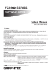
Flow of setup
Setting up the Plotter main unit
1. Attaching a Tool
The cutter blade can replaced depending on the material or thickness of the
media.
P.03
2. Loading Media (Paper or Marking Film)
Fix the media to the Plotter.
P.04
3. Aligning the Push Rollers
Adjust the position of the push roller.
P.09
4. About the Initial Setup screen
Select "Display Language" and "Length Unit".
P.10
5. Set the media type into the Plotter
Set the media type to the Cutting Plotter, depending on the set media.
P.10
6 Tool adjustment and test cutting
Adjust the protruded cutter edge length and the cutting Force depending on the material
and thickness of the media. Make test cutting for the set media to adjust the best condition.
P.11
For each software of CE6000 install them using the Installer housed in the
attached DVD-ROM.
P.14
Installing the Cutting Plotter Controller
Once Cutting Plotter Controller is installed, you can control main functions of
CE6000 through the PC.
P.15
Installing the CE6000 Driver (Cutting Plotter
Driver)
The CE6000 Driver software controls the Plotter and makes plotting according
to the data created by the PC.
P.16
Installing the Software
Launching the Start menu
A. Install CE6000 Software
The procedures vary depending on the Interface.
• To connect using the USB
Turn on the power source of Plotter in the middle of installing, and connect the USB cable.
P.16
• To connect using the RS-232C
Connect the RS-232C cable after installing is finished.
P.16
B. Setup the Graphtec Studio
Software enabling cutting data to be created through simple commands.
Create designs and edit characters/shapes using this software.
P.17
C. Setup the Cutting Master 3
Plug-in driver that enables simple cutting through direct operation from within
Adobe Illustrator and CorelDRAW.
P.18
D. Install the User's Manual
Installs the CE6000 User's Manual.
P.19
Install the software as necessity.
Setting up the Plotter main unit
1. Attaching a Tool
Attach a tool (cutter plunger, plotter pen) to the plotter.
Attaching a Tool
When mounting the tool in the tool holder, please note the following.
the tool all the way into the holder until its flange contacts the upper part of the holder and then tighten the screw
•Push
firmly.
prevent injury, avoid absolutely touching the tool immediately after the cutting plotter is turned on or whenever the tool
•To
is moving.
For details, see “Attaching a Tool” on P.2-4
in CE6000 User’s Manual.
It is explained here using cutter plunger as an example.
CAUTION
When pushing the tool holder with your fingers, the blade tip may be protruding. Take care not to cut your fingers.
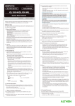
1 Loosen the tool holder screw.
Bracket to hold tool
Tool holder
Tool holder
Bracket to hold tool
Top
2 While pushing up the tool holder, push until its flange completely touches
the upper part of the holder.
Bracket to
hold tool
Flange
Tool holder
3 Make sure that the tool bracket is engaged on the tool's flange, and then tighten the screw.
Bracket to hold tool
Flange
Removing the tool
When removing the tool, turn it counterclockwise to remove the tool.
2. Loading Media (Paper or Marking Film)
Both roll media and sheet media can be used with the CE6000.
Load the media according to the instructions given for each type. Use the grit roller on the right side of the media (looking
from the front) as a guide when setting it in the media sensor. Afterwards, adjust the push roller so that it's lined up with the
side of the media.
For details, see CE6000 User's Manual (PDF).
This will be explained mainly in CE6000-120.
Loading Roll Media
1 Lower the media set lever to raise the push rollers.
Push roller
Media sensor
Media set
lever
Supplement
For more information about the position of the
push roller, see "Adjust the Push Roller" on
.
P.9
2 Set the roll media on top of the stock shaft, and then insert the roll media into the stopper. Once it's set, tighten the
stopper's screws.
3 Push the tip of the roll media forward from the back of the CE6000.
Make sure to pull it so that there is no slackening across the roll media's
route.
4 Press the media stopper to engage it, and then pull the leading edge
This stops the stock shaft from spinning when
setting in media. It is also utilized when pulling
roll media straight out.
The media stopper is attached to CE6000-60/
120 only.
Media sensors
Media stopper
Put the roll media on the roll media tray and
then push the tip of the roll media forward from
the back of the machine.
Media stopper
out of the front of the plotter, making sure that it completely covers the
media sensor.
Slide the
media
stopper
When using CE6000-40
Supplement
When actually cutting, please release the lock
from the media stopper (while pulling to the
exterior, slide it forward). (See P.7
)
5 Position the media and the push rollers to correspond with the width of
the media.
When the CE6000-40/60
The push rollers push down on either side of the media. Use the grit
roller position guide to make sure the push rollers are set on top of the
grit rollers.
Push roller
Grit roller
Grit roller position guide
Push roller
Media
Media sensor
Supplement
media must always be positioned over
•The
the media sensor.
"Aligning the Push Rollers" P.9
•See
about the position of the push rollers.
When the CE6000-120
Use the 3 push rollers to push down the sides and center of the media.
Use the grit roller position guide and make sure the push rollers are on
top of the grit rollers.
You can adjust the center push roller's hold-down force.
Push roller
Grit roller position guide
Push roller
Supplement
media must always be positioned over
•The
the media sensor.
"Aligning the Push Rollers" P.9
•See
about the position of the push rollers.
"Aligning the Push Rollers" P.9
•See
for information about push roller hold-down
force.
Grit roller
Media sensor
(The push roller is on top of the grit roller.)
(The push roller is on top of the grit roller.)
(The center push roller is not on top of the
grit roller.)
(The center push roller is near the edge.)
When Feeding Long-axis Media (at exceeds 2 meters)
Position the push rollers at least 15 mm inside the edges of the media.
Push roller
15mm
15mm
Media
When Feeding Long-axis Media (at least 2 meters)
Position the push rollers at least 5 mm inside the edges of the media.
Push roller
5mm
Media
5mm
6 Pull the media taut to make sure that there is no slack in the conveyance path, and then raise the media set lever to
lower the push rollers.
Media set lever
7 Release the lock from the media stopper (Pull the sides and slide it forward).
Release
the media
stopper
Media stopper
8 When the set lever is up (and the media is held down by the push rollers)
and the media stopper is unlocked, pull out the roll media and give it
slack.
Supplement
Dirt from the floor may stick to the media when
giving it slack, so please be careful.
Give it slack
Create the same amount of slack in the media as will be used for the
back of the machine.
When the CE6000-40
Create the same amount of slack in the media
as will be used for the back of the machine.
Step 1:Raise the set lever
and fix the media.
Step 2: Create slack.
Give it slack
Loading Sheet Media
1 Lower the media set lever to raise the push rollers.
Media sensor
Push roller
Media set lever
Supplement
See "Aligning the Push Rollers" P.9
about the position of the push rollers.
2 Make sure that the sheet media completely covers the media sensor.
Media sensor
3 Position the media and the push rollers to correspond with the width of
the media.
Supplement
Refer to the description of "Loading Roll
Media". (See P.5
and P.6
.)
When the CE6000-40/60
4 Pull the media taut to make sure that there is no slack in the conveyance path, and then raise the media set lever to
lower the push rollers.
Set the sheet media so that the paper's edges line up with the guideline on the front side.
Media set lever
Line up
When the CE6000-120
4 Pull out the front media under the media guide bar.
Media guide bar
5 You can set the media straight by stacking media you pull out and matching the edges up together.
After you check to make sure there's no slack, raise the media set lever and fixate the sheet media in the push roller.
Media set lever
Line up
Media guide bar
3. Aligning the Push Rollers
This section describes how to alignment of the push rollers.
Aligning the Push Roller
Position the left and right push rollers to correspond with the width of the media. Adjust the push rollers so that they are
positioned above both the media and the grit rollers.
Position the push rollers within the grit roller position guides ensures that they are above the grit rollers.
Push roller
Grit roller position guide
(It isn't on the grit roller.)
(It isn't on the grit roller.)
Grit roller
CAUTION
To move the push rollers, the media set lever must be in the lowered position.
Supplement
If a [confirming push roller point] message appears after setting the media and raising the media set lever, it means the right push
roller is not on the right grit roller, or that the left or center (CE6000-120) push roller is not on the proper grit roller. Make sure
everything is set correctly.
For minimum width media
Make sure that all push rollers are on the long right grit roller.Use the left side of the grit roller as a starting point and then
set the push rollers so that they're on both sides of the media.
The CE6000-40/60 can take media of 55 mm or more, and the CE6000-120 can take media of 90 mm* or more.
* When using the CE6000-120, and all push rollers are on the right grit roller (wide),
turn the center (all rollers but the side rollers) push roller hold-down force OFF.
CE6000-40/60
CE6000-120
Grit roller
Grit roller
Push roller
Push roller
Supplement
The CE6000-120 requires the center push
roller hold-down force to be set based on the
media's width and material type in order to
keep the media in place. (This only applies to
the CE6000-120)
Media sensor
Media sensor
Media
Media
Lever
Hold-down force:
Normal
Lever
Hold-down force: Low
(OFF)
Refer to "Changing the Hold-down Force" on
P.2-24 .
4. About the Initial Setup screen
The Initial Setup screen appears only when powering up the Cutting Plotter for the first time after purchase. Here, you can
set "Display Language" and "Length Unit".
After the initial setup is completed, you can also select the menu from the READY status.
See "2.6 Connecting to the Power" P.2-26 for turning on the power.
1 Once the machine is powered on (with the " | " switch) a message will be displayed after the version is displayed.
2 Use the POSITION (
3 Press the [ENTER] key.
4 Press the [1] key (METRIC) or the [2] key (INCH) to select the length unit setting.
5 Confirm the setting and press the [ENTER] key (SET).
Here, PLEASE DISPLAY LANGUAGE setting screen is displayed.
) keys to select the language.
(This manual assumes you chose the English language setting.)
After the DISPLAY LANGUAGE is selected, the LENGTH UNIT screen will appear.
Setting will be set, and the default screen is displayed.
5. Set the media type into the Plotter.
Set the media type into the Plotter depending on the preset media.
1 If you have already loaded the media, the MEDIA TYPE menu appears.
Select the media type to suit the loaded media.
CAUTION
Release the media stopper in CE6000-60/120.
Supplement
Plot starting with the edge of
media.
Plot starting with the preset
position.
Sheet media Set a sheet media.
CONTINUE When similar media is reset
Roll media
The CONTINUE menu parameter appears when
the media set lever is raised and then lowered
again after media was previously loaded, making
it possible to select the previous settings.
[1] ROLL-1 FRONT EDGE
[2] ROLL-2 CURRENT POSITION
[3] SHEET
[4] CONTINUE
2 After the media is detected, the plotter is ready to receive data for cutting
or plotting. This status is called "READY status" of the default screen.
When setting is finished, the tool carriage's location will become the
initial point.
Dfault screen is displayed.
Menu screen
(Normal mode)
Menu screen
(Simple mode)
10
Simple mode/ Normal mode
You can use the [SIMPLE] key on the default
screen to switch between Simple mode and
Normal mode. CE6000 will be reset once when
you switch.
In Simple mode you can change easy settings
from the menu screen.
In Normal mode, you will be able to change
more detailed settings.
Simple mode and Normal mode are independent
from one another. The settings of the mode
you're currently in will take precedence.
For details, see "About Simple mode" on page
P.2-54 .
6. Tool adjustment and test cutting
After setting the Tool/Speed/Force/Acceleration, make test cutting, and repeat until optimal condition is achieved.
1 Load the media for test cutting in the plotter.
2 Press the [COND/TEST] key in the default screen.
Do not touch the Tool edge when power is
turned on or during operation.
In Normal mode, CONDITION screen (1/3) is displayed.
In Simple mode, CONDITION screen (1/5) is displayed.
CONDITION screen
(Normal mode)
CAUTION
CONDITION screen
(Simple mode)
3 Set the Tool conditions (Tool, Speed, Force, Acceleration).
Setting the Tool conditions
For more information about the various cutting
conditions, see “Selecting Tool Condition” on
page P.2-35 .
Ex.) TOOLS CONDITION
Settings screen (Normal mode)
Ex.) TOOLS CONDITION
Settings screen (Simple mode)
To make 1 cut with set value
4 Make test cutting for one piece while Tool conditions are
being set.
CONDITION screen
(Normal mode)
To make 3 cuts with set value and ±1 of set value
4 Make test cutting for three pieces while Tool conditions
are being set.
CONDITION screen
(Normal mode)
CONDITION screen
(Simple mode)
CONDITION screen
(Simple mode)
(1) Press the POSITION ( ) key (CUT TEST).
(1) Press the POSITION ( ) key (CUT TEST).
CUT TEST screen is displayed.
CUT TEST screen
(Normal mode)
(2) Press the POSITION (
) key the tool carriage
to the location you wish to perform the test cutting.
CUT TEST screen
(Simple mode)
(2) Press the POSITION (
) key the tool carriage
to the location you wish to perform the test cutting.
Tool carriage
(3) Press the [1] key (FORCE).
3 cutting test patterns are cut,
with current FORCE in the
center, and 1 each of FORCE
increased and decreased for 1
Cut Order
+1
Setting
values
–1
(4) Press the [ENTER] key after completion.
It will return to CUT TEST menu screen.
Press the [ENTER] key.
Cut test pattern is cut.
(5) Press the [2] key (CUTTER OFFSET). (Normal mode
only)
CAUTION
3 cutting test patterns are cut, with current CUTTER
OFFSET in the center, and 1 each of CUTTER OFFSET
increased and decreased for 1.
When the [ENTER] key is
pressed, the tool carriage
will start moving, so take
care not to cut your fingers.
(6) Press the [ENTER] key after completion.
It will return to CUT TEST menu screen.
11
5 Check if the cut test is appropriate.
Confirm the cutting test results, and adjust to optimal setting. Repeat cutting test and adjustment until optimal cut is
achieved.
Adjustment of Offset
Check the corners of the triangles and rectangles. See "Setting the Tool"
and adjust the offset value if the corner is not cut or if it is cut
P.2-35
too much.
Adjust offsets in Normal mode.
Adjustment for Half Cutting
Peel off the triangle area, and adjust so it cuts slightly into the backing
sheet.
If the backing sheet has been cut through, either the FORCE setting is
too high or the cutter-blade tip is extended too far. If the backing sheet
shows only a few traces of the cutter blade, either the FORCE setting is
too low or the cutter blade tip is not sufficiently extended.
See "Adjusting the Blade Length" P.2-2
and "Setting the Force"
and adjust the settings.
P.2-44
How to check offset
Check if the offset value is set correctly by
following.
Not enough adjustment. Increase
the offset value.
Optimal offset value.
Too much adjustment. Decrease
the offset value.
Adjustment for Cutting Out
Adjust so the media is completely cut out.
If the media is not completely cut, either the FORCE setting is too low or the cutter blade tip is not sufficiently extended.
See "Adjusting the Blade Length" P.2-1
and "Setting the Force" P.2-44 and adjust the settings.
Adjustment When Using Plotting Pen
Adjust the FORCE so there will be no faint lines. To prolong the pen life, set the FORCE to the lowest setting without any
faint lines. See"Setting the Force" P.2-44 or setting the FORCE.
Adjust the Blade Length (Automatic Height Adjust)
Test cutting must be performed several times in order to confirm the optimal blade length setting. However, if the blade
length adjustment function is used, the optimal length can be easily set.
1 Load the media for test cutting in the plotter.
2 Press the POSITION (
3 Press the [COND/TEST] key in the default screen.
) key the tool carriage to the location you wish to perform the blade length adjustment.
Supplement
CONDITION setting screen (1/3) is displayed.
4 Press the POSITION (
Perform the settings in Normal mode.
) key.
CONDITION setting screen (3/3) is displayed.
5 Press the [3] key (BLADE ADJUST).
Message prompting to turn the blade-length adjustment knob is displayed.
12
6 As instructed, turn the blade length adjustment knob to the left to fully
retract the blade.
CAUTION
Do not touch the Tool edge when power is
turned on or or during operation.
Supplement
See "Structure of Cutter Plunger"
bladelength adjustment knob.
P.2-2
for
Blade
7 Set the cutter Plunger in Tool Holder 1 (Backward).
8 Press the [ENTER] key.
Supplement
You can calculate the height by moving the tool up and down.
TO ACHIEVE THE TARFET LENGTH screen is displayed.
Adjustment is only possible for the cutter pen
set in Tool Holder 1 (Backward). It does not
apply to Tool Holder 2 (Forward).
See "Attaching a Tool" P.3
for
instructions on setting.
9 Press the [1] key (BLADE LENGTH TARGET).
BLADE LENGTH TARGET screen (TARGET) is displayed.
10 Press the POSITION (
) key and increase or decrease the setting value.
11 Confirm the settings and press the ENTER key (SET).
The Blade Length Target will be selected, and you will return to the TO
ACHIEVE THE TARGET LENGTH screen.
12 Press the [2] key (CHECK).
You can calculate the height by moving the tool up and down.
The amount and direction to turn the adjustment knob is displayed.
13 Turn the blade-length adjustment knob and adjust the cutter blade length.
[2] Current blade length is displayed by pressing the [2] key (CHECK) , so
adjust the blade length until it matches the thickness of the media.
14 Press the [3] key (END).
Adjustment is completed and it will return to CONDITION screen (3/3).
15 Press the [COND/TEST] key.
I will be return to default screen. After completing the settings, press [ENTER] key.
13
Supplement
"T" is the target value of the blade length, and
"H" is the current blade height (amount).
Turning the blade-length adjustment knob
displays the number of turns and direction.
CAUTION
Depending on the loaded media, the blade
might sink in to the media, making accurate
measurement impossible.
Installing the Software
Install the software housed in the attached DVD-ROM into the PC that is used.
This section explains how to install the software when using a Windows 7 (32 bit) operating environment.
Note
installation, be sure to log on Windows using an account with administrator privileges on your computer.
•Upon
If you have logged on using a standard user account, an [User Account Control] screen asking you to enter the
administrator account password may appear.
•
When Using Macintosh
•*1:
Macintosh operating environments are supported by the following software.
Supported OS
This software supports the following OS environments:
Windows 8 (32 bit/64 bit), Windows 7 (32 bit/64 bit), Windows Vista (32 bit/64 bit), Windows XP (32bit/64bit),
Mac OS X (10.5.8 or later)*1 [Intel CPU (PPC is not supported)]
Proceed with installation in accordance with your operating environment.
• Graphtec Studio:Software application that enables cutting data to be created through simple commands.
• Cutting Master 3:Plug-in driver that can be directly operated from within Adobe Illustrator.
Note that Adobe Illustrator must be installed on your computer prior to use.
When installing the above software to your Macintosh operating environment, refer to the respective manual for each
included on the accompanying DVD-ROM.
•Open the pertinent manual on the accompanying DVD-ROM in the following sequence: [Manuals] > [English (Each
Language)] > [Manual According to Software]
1. Launching the Start Menu
After starting up Windows, insert the [USER GUIDE & SOFTWARE DVD] provided with the CE6000 into your computer's
DVD drive.
The below screen will appear before the Start Menu launches.
Continue with installation in accordance with the following procedures.
1 The Windows [AutoPlay] screen will appear.
Select [Run MultiSetup.exe] from the Windows [AutoPlay] screen.
*If the [AutoPlay] screen does not appear, open [Explorer] and select the DVD drive containing the software to be installed.
Open the DVD and double-click on [MultiSetup.exe].
2 Click [Yes] if you have logged on using an administrator account.
Supplement
If you have logged on using a standard user
account, an [User Account Control] screen asking
you to enter the administrator account password
may appear. Enter the password, and then click
[Yes].
14
3 The [Start] will appear.
"Use this menu to install the software you require to use the CE6000.
First-time users should proceed with installation by clicking on [Install CE6000 Software]."
Proceed with installation according to your operating environment.
A
B
C
D
A.Install CE6000 Software:
Install the [Cutting Plotter Controller] and [Plotter Driver].
The [Cutting Plotter Controller] enables various cutting conditions, plotter
settings, etc. to be controlled directly from your computer.
B.Setup Graphtec Studio:
"Software enabling cutting data to be created through simple commands.
Create designs and edit characters/shapes using this software."
C. Setup Cutting Master 3:
Plug-in driver that enables simple cutting through direct operation from
within Adobe Illustrator and CorelDRAW.
Adobe Illustrator or CorelDRAW must be installed on your computer prior
to use.
D.Install User's Manual:
Installs the CE6000 User's Manual.
A. Install CE6000 Software
If you are using the CE6000 for the first time, click on [Install
CE6000 Software] to install the device.
This operation will install the [Cutting Plotter Controller] and
[Plotter Driver].
Note
2 The [Chose Destination Location] screen will appear.
3 The [Select Program Folder] window will appear.
4 When the next screen appears, click on [Finish].
Check the installation destination folder displayed. If
there is no need to change it, click on [Next].
Simply click on [Next].
Do not connect the accompanying USB cable yet.
Doing so may prevent the [Plotter Driver] from
being installed properly.
Refer to the procedures in this User's Manual
when connecting the USB cable.
Installing the [Cutting Plotter Controller]
1 Click on [Install CE6000 Software].
The [Setup] screen to setup Cutting Plotter Controller
for CE6000 will appear momentarily.
Click on [Next].
This concludes the installation of the [Cutting Plotter
Controller].
Next, install the [Plotter Driver].
15
Installing the [Plotter Driver]
5 After installation of the [Cutting Plotter Controller] is
9 Continue with the installation process while following
the on-screen instructions.
complete, the [Setup] screen for the [Graphtec CE6000
Driver] will appear momentarily.
When it does, click on [OK].
10 The [Windows Security] screen will appear momentarily.
Click on [Install] to install the [Plotter Driver].
6 Next, check to make sure the [CE6000] is not
connected to your computer, then click on [Next].
11 Next, the [Update for the Graphtec CE6000 driver was
completed] screen will appear.
Click on [OK] to reboot your computer.
7 Click on [Next] again.
This concludes the installation of the [Plotter Driver].
After rebooting your computer, follow the below procedures
to connect the USB cable.
8 A window for selecting the [Port Name] to be used
appears.
Select [USB].
Clicking on [Next] will begin the driver installation
process.
Connecting the USB Cable
12 First, make sure that Windows 7 has been launched
Available Port Names
USB :Selected when a USB cable is used for
connection.
COM1:Selected when an RS-232C (serial) cable is
used for connection.
FILE :Selected to save outputted data (plot data) to
a file.
successfully.
Next, connect the USB cable accompanying the
CE6000 to your computer. Ensure that the CE6000 is
turned off when you do.
(1) Ensure that the Plotter's power is turned off (" "
position).
Select "USB"
(2) Connect the power cable.
Supplement (When selecting the COM1)
To select "COM1" in "Selecting Port Name", do the
installation according to the message.
After the installation is completed, connect the RS-232C
cable. ( P.1-16
For more information about connecting
the RS-232C cable, see "1.4: Connecting the computer" on
page 1-6 in CE6000 User's Manual.)
To connect the COM1 for RS-232C, the Cutting Plotter
must be set to "Normal mode". For more information about
setting the COM1, see P.2-1
"Chapter 2: Preparing to
Cut" on page 2-1 in CE6000 User's Manual.
16
16 Click on [Yes] on the next screen.
(3) Connect the USB cable.
1. Connect to your computer.
2. Connect to the
Cutting Plotter.
17 The [Your Device is ready to use] screen will appear
USB cable
13 Turn on the CE6000 unit.
This concludes the installation of the driver software.
Next, please install the software applications.
Install the software in accordance with your operating
environment.
14 A message will appear momentarily on the bottom-right
momentarily.
Click on [Close].
of your Windows screen.
Click on this message.
15 The [Driver Software Installation] screen will appear.
Click on [Skip obtaining driver software from Windows
Update].
B. Setup Graphtec Studio
Installing "Graphtec Studio"
Graphtec Studio is a software application that enables
cutting data to be created through simple commands.
Create designs and edit characters/shapes using this
software.
17
1 Click on [Setup Graphtec Studio].
The [Graphtec Studio Setup] screen will appear
momentarily.
Click on [Next].
2 The [Select Installation Folder] screen will appear.
Check the installation destination folder displayed. If
there is no need to change it, click on [Next].
4 When this screen appears, click on [Finish].
This concludes the installation of [Graphtec Studio].
3 The [Ready to Install] screen will appear.
Click on [Install] to begin installation.
C. Set Up Cutting Master 3
This plug-in driver enables simple cutting through direct
operation from within Adobe Illustrator and CorelDRAW.
Note that Adobe Illustrator or CorelDRAW must be installed
on your computer prior to use.
Installing "Cutting Master 3"
1 Click on [Setup Cutting Master 3].
The [Cutting Master 3 Setup] screen will appear
momentarily.
Click on [Next].
*On-screen prompts will be displayed in English while
installing [Cutting Master 3 Setup].
*Note that on-screen prompts will be displayed in English
during standard usage following installation.
18
2 The [Select Installation Folder] screen will appear.
3 The [Ready to Install] screen will appear.
Check the installation destination folder displayed. If
there is no need to change it, click on [Next].
Click on [Install] to begin installation.
4 When this screen appears, click on [Finish].
This concludes the installation of [Cutting Master 3].
D. Install User's Manual
Follow the below procedures to install the CE6000 User's
Manual (pdf format).
Adobe Reader must be installed on your computer in order
to read the manual.
The newly-installed [User's Manual] will be registered
under your Windows Start Menu.
Installing "User's Manual"
1 Click on [Install User's Manual].
2 When this screen appears, click on [Finish].
The [CE6000 User's Manual Setup] screen will appear
momentarily.
Click on [Next].
This concludes the installation of the [User's Manual].
19
621589821