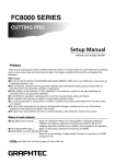
1
User’s Manual
MANUAL NO.CC100m-UM-152
PREFACE
PREFACE
Thank you for purchasing the Craft ROBO CC100. Based on cutting-plotter technology developed by Graphtec
over many years, CC 100 provides outstanding flexibility in operation. It can be used for cutting heavy cardstock,
paper and sticker film as well as pen plotting. Please read this manual thoroughly and assure proper use of the
equipment.
Warning
Only computers or peripherals (computer input/output devices, terminals, printers, etc.) certified as complying with
the limits for a Class B digital device, pursuant to Part 15 of the FCC Rules, may be attached to this product when
this product is operated in a residential environment. Operation with non-certified peripherals is likely to result in
interference to radio and TV.
Federal Communications Commission Radio Frequency Interference Statement
“This equipment has been tested and found to comply with the limits for a Class B digital device pursuant to Part
15 of the FCC Rules. These limits are designed to provide reasonable protection against harmful interference in a
residential installation. This equipment generates, uses, and can radiate radio frequency energy and, if not
installed and used in accordance with the instructions, may cause harmful interference to radio communications.
However, there is no guarantee that interference will not occur in a particular installation. If this equipment does
cause harmful interference to radio or television reception, which can be determined by turning the equipment off
and on, the user is encouraged to try to correct interference by one or more of the following measures:
– Reorient or relocate the receiving antenna.
– Increase the separation between the equipment and receiver.
– Connect the equipment into an outlet on a circuit different from that to which the receiver is connected.
– Consult the dealer or an experienced radio/TV technician for help.”
Notes on this Manual
(1) No part of this publication may be reproduced, stored in a retrieval system, or transmitted, in any form or by
any means, without the prior written permission of Graphtec Corporation.
(2) The product specifications and other information in this manual are subject to change without notice.
(3) While every effort has been made to provide complete and accurate information, please contact your sales
representative or nearest Graphtec vendor if you find any unclear or erroneous information or wish to make other
comments or suggestions.
(4) Notwithstanding the stipulations in the preceding paragraph, Graphtec Corporation assumes no liability for
damages resulting from either the use of the information contained herein or the use of the product.
Registered Trademarks
All names of companies, brands, logotypes, and products appearing in this manual are the trademarks or
registered trademarks of their respective companies.
Copyright
This User’s Manual is copyrighted by Graphtec Corporation.
I
CONTENTS
CONTENTS
PREFACE.............................................................................................................................................I
Warning ......................................................................................................................................I
Federal Communications Commission Radio Frequency Interference Statement....................I
Notes on this Manual .................................................................................................................I
Registered Trademarks..............................................................................................................I
Copyright ....................................................................................................................................I
CONTENTS.........................................................................................................................................II
CHAPTER 1. PRIOR TO USE
1.1
1.2
Check all the items................................................................................................................ 1-1
Craft ROBO Parts and Functions.......................................................................................... 1-2
Craft ROBO (CC100) ............................................................................................................ 1-2
CHAPTER 2. CONNECTION AND PREPARATION
2.1
2.2
2.3
2.4
Connecting the Power Adapter ............................................................................................. 2-1
Connecting to a Computer .................................................................................................... 2-1
Loading Media....................................................................................................................... 2-2
Loading Method .................................................................................................................... 2-2
When the Media warps up ............................................................................................... 2-3
Media Size ....................................................................................................................... 2-3
Cutting area........................................................................................................................... 2-4
Using the carrier sheet .......................................................................................................... 2-5
Using a Carrier Sheet for smaller than Letter Size media ............................................... 2-5
Using a Carrier Sheet for Letter Size media .................................................................... 2-6
Cutting area of the carrier sheet ........................................................................................... 2-7
Setting the Blade Length....................................................................................................... 2-8
Blade holder description........................................................................................................ 2-8
Blade adjustment caps and media selection......................................................................... 2-9
Changing the blade adjustment caps.................................................................................... 2-9
Installing the blade holder ................................................................................................... 2-10
Ballpoint pen installation ..................................................................................................... 2-11
Installing the ballpoint pen................................................................................................... 2-12
CHAPTER 3. CRAFT ROBO CONTROLLER
3.1
3.2
3.3
3.4
3.5
3.6
The Craft ROBO Controller ................................................................................................... 3-1
Operating Environment ......................................................................................................... 3-1
Installing the Craft ROBO Controller..................................................................................... 3-2
Starting up the Start window ................................................................................................. 3-2
Installing the Controller ......................................................................................................... 3-3
Using the Craft ROBO Controller.......................................................................................... 3-5
Starting up the Craft ROBO Controller.................................................................................. 3-5
Cutter Operation.................................................................................................................... 3-8
Craft ROBO Controller Components................................................................................... 3-11
Messages ............................................................................................................................ 3-23
Appendix A. Standard Specifications ................................................................................. Appendix-1
INDEX.........................................................................................................................................Index1
II
CHAPTER 1. PRIOR TO USE
CHAPTER 1. PRIOR TO USE
1.1 Check all the items
Referring to the list below, check to confirm that all components are included with your product. If any item is
missing, please contact your place of purchase.
AC adapter, AC adapter Power cable ....1
USB cable ....1
Craft ROBO Software CD-ROM ....1
Quick Start Instructions ....1
Quick Application Guide ....1
Media Trial Kit ....1
Standoff ring ....1
Blade holder with blade adjustment cap ....1
Ballpoint penholder ....1
Blade adjustment caps .... 2
1-1
CHAPTER 1. PRIOR TO USE
1.2 Craft ROBO Parts and Functions
Craft ROBO (CC100)
Cutting head
LED lamp
Feed knob
Ballpoint pen holder
Pinch roller
Blade holder and Clamp bracket
Standby switch
AC adapter jack
USB interface connector
Work surface
Cutting mat
Guideline
Media roller
Feed knob ..........................Manually feeds media in and out
Cutting Head ......................Drives the blade holder to the left or right
Ballpoint penholder...........Used for plotting using a ballpoint pen
Blade holder.......................Used for cutting using a blade
Clamp bracket....................Holds the blade holder/penholder and drives it up or
down
Standby switch ..................Turns on and off the cutter
LED lamp............................The light is on when unit is ready to operate and flashes
when data is received
USB interface connector...Used for connecting USB cable
AC adapter jack .................Used for connecting AC/DC power adapter cable
Pinch roller.........................White rollers that tightly holds media in place, assuring
accurate operation
Guideline ............................Used as a guide when media is loaded in
Work surface......................Used for media support and alignment
Media roller ........................Prevents media from warping
Cutting mat ........................A black strip that protects work surface from damage
caused by the blade
1-2
CHAPTER 2. CONNECTION AND PREPARATION
CHAPTER 2. CONNECTION AND PREPARATION
2.1 Connecting the Power Adapter
Connect the AC adapter jack of the cutter to the AC outlet of the rated voltage using the AC adapter included with
the Craft ROBO and turn on the power.
Always connect to the AC adapter jack before connecting to the AC outlet.
1.
Connect the power cable (included with the AC adapter) to the AC adapter.
2.
Plug the AC adapter cable into the AC adapter jack of the cutter.
3.
Plug the other end of the power cable into the AC outlet.
2.2 Connecting to a Computer
Connect the cutter to a computer via USB cable.
Use a USB cable to connect the cutter to a computer. The USB cable has different
plug shapes on the computer side and the main-unit side. Always check which plug
connects to which side.
Do not connect two or more units of the Craft ROBO to one computer. Do
not connect the Craft ROBO and a Graphtec plotter to a computer at the
same time. Otherwise, the Craft ROBO may not operate properly.
2-1
CHAPTER 2. CONNECTION AND PREPARATION
2.3 Loading Media
Loading Method
Do not load media without a backing sheet or carrier sheet, or perform a
cutting operation when there is no media; either will damage the cutting
mat.
1.
Press the standby switch, and confirm that the LED lamp is lit.
2.
If there is a loading direction printed on the sheet, load the sheet to the Craft
ROBO accordingly.
LED lamp
Standby switch
3.
While making sure the media is straight, align the left edge of the sheet with the
guideline.
Place the top edge of media against
the white pinch rollers.
Align the media with the guideline
(indented) on the work surface.
4.
Turn the feed knob counterclockwise (away from you) and feed the sheet until it
is aligned with the top edge of the black cutting mat.
Cutting mat
2-2
CHAPTER 2. CONNECTION AND PREPARATION
When the Media warps up
If the leading edge of the media is warped up and interferes with the blade tip,
continue to feed the media until it aligns with the indented guideline located behind
the cutting mat. This allows the media to feed properly but reduces the potential
cutting area by 5 mm in the feed direction.
Align the edge of the media with the
guideline (indented) at the rear of the unit.
Media Size
Vinyl and medium that already have backing sheets (liners) can be between 210 and
260 mm in width and up to 1000 mm in length. Scraps of media without backing
sheets (liners), starting from 100 mm in width, can be placed on the carrier sheet
provided with the cutter.
2-3
CHAPTER 2. CONNECTION AND PREPARATION
Cutting area
Available cutting area is shown in the diagram below. In addition, make sure that media edges are parallel with
the cutting guideline.
The possible cutting area varies with the mode you select.
In standard mode the cutting area is 190 mm in width.
In expanded mode the cutting area is 200 mm in width.
If registration marks are used the cutting area is 190 mm in width.
The above numbers are true only when media is loaded correctly along
the guideline.
10 mm
10 mm
5 mm
5 mm
5 mm
Possible cutting
area
Possible cutting
area
Media
20 mm
20 mm
Standard
2-4
5 mm
Expanded
CHAPTER 2. CONNECTION AND PREPARATION
Using the carrier sheet
The carrier sheet allows media smaller than Letter size and media without a backing sheet (liner) to be cut.
• For cutting out the media, always be sure to use the carrier sheet.
• The carrier sheet is removable, so can be used repeatedly. When its
adhesive power becomes weak, however, replace it with a new carrier
sheet.
• The carrier sheet is a consumable. Replace it after cutting
approximately 10 sheets. Using a carrier sheet for more than 10
sheets may cause misaligned cutting or other problems. Actual
number may vary depending on a type of cut media.
• Pulling out the carrier sheet without turning the feed knob may
shorten its life, causing misaligned cutting. Always be sure to turn the
feed knob to remove the media.
Using a Carrier Sheet for smaller than Letter Size media
Do not use media smaller than 100 mm.
1.
Peel off only the inside liner of the carrier sheet, so that the adhesive surface is
visible. (When using the carrier sheet, do not peel off the liner strips on both
sides.)
Liner
Peel off only the inside liner.
2.
Press the media onto the adhesive surface of the carrier sheet.
When pressing the media, be careful not to cause air bubbles or
wrinkles in the media.
Media
Adhesive surface
Carrier sheet
2-5
CHAPTER 2. CONNECTION AND PREPARATION
Using a Carrier Sheet for Letter Size media
Do not use media larger than 210 mm in width.
1.
Peel off the liner inside and on both sides of the carrier sheet, so that the
adhesive surface is visible.
Liner
Peel off the liner inside and on both
sides of the backing sheet.
2.
Press the media onto the adhesive surface of the carrier sheet, making sure that
the edges of the media are aligned with the carrier sheet.
When pressing the media, be careful not to cause air bubbles or
wrinkles in the media.
Media
Adhesive surface
Carrier sheet
2-6
CHAPTER 2. CONNECTION AND PREPARATION
Cutting area of the carrier sheet
The available cutting area of the carrier sheet is shown in the diagram below. When using media smaller than
Letter size, always place the media within the cutting area. In addition, make sure the media is set parallel to the
edges of the carrier sheet.
Do not use media smaller than 100 mm.
Cutting area
Media
Carrier sheet
2-7
CHAPTER 2. CONNECTION AND PREPARATION
2.4 Setting the Blade Length
Blade adjustment cap controls the blade length. To obtain better cutting results, select the blade adjustment cap
of the blade holder according to the type of media to be cut.
The length of the blade protruding from the cap should not exceed the
thickness of the media, otherwise the cutting mat may be damaged.
Caution
When handling the cutter blade, exercise care to prevent injuring your hand.
Blade holder description
The length of the blade protruding from the cap can be adjusted by selecting one of
the three available blade adjustment caps.
Select the blade adjustment cap best suited for the media in use. Always perform a
test cut to assure proper blade length.
Blade holder
Blade adjustment cap
Blue:
Thin film
Yellow: Thick film, thin paper
Red:
Thick paper such as a postcard
Blade
2-8
CHAPTER 2. CONNECTION AND PREPARATION
Blade adjustment caps and media selection
Select and set the blade adjustment cap best suited to the media in use
Selection guide for blade adjustment caps
Cap
Blue
Yellow
Red
Media
Thin film
Thick film, thin media
Thick media
Changing the blade adjustment caps
The blade adjustment cap is a screw-on type.
Blade
adjustment cap
Blade holder
1. Turn it in the counterclockwise direction to remove the cap.
2. Replace with the correct blade adjustment cap.
3. Turn it in the clockwise direction to tighten the cap.
Loosen
Tighten
Blade holder
Blade adjustment cap
2-9
CHAPTER 2. CONNECTION AND PREPARATION
Installing the blade holder
Insert the blade holder that has had its protruding blade length adjusted into the
cutter.
Caution
When handling the cutter blade, exercise care to prevent injury.
When using the carrier sheet, use the standoff ring included with the
Craft ROBO.
Hold the clamp bracket tightly while attaching or removing the blade
holder.
1.
Turn the lock lever to the left (OPEN direction) and remove the blade holder.
Firmly insert the blade holder in place
until this face contacts the holder.
2.
When using the carrier sheet, always use the standoff ring included with the
Craft ROBO. Standoff ring compensates for the blade depth when using the
carrier sheet. Attach the standoff ring to the blade holder before setting the blade
holder in place.
Standoff ring
3.
2-10
Lock lever
Attach the Standoff ring to the cutter
pen, and firmly insert it in place.
Insert the blade holder in the clamp bracket and turn the lock lever to the right
(CLOSE direction).
CHAPTER 2. CONNECTION AND PREPARATION
Ballpoint pen installation
The ballpoint penholder accepts cylinder pens up to 8.5 mm in diameter or hexagon
shaped pens up to 7.5 mm side-to-side and whose tips extend between 3 and 3.5
mm past the ballpoint penholder’s opening.
Thumb
screw
Cylindrical
ball-point pen
Hexagonal Ball-point pen
Tip of the pen
ball-point pen
holder
2-11
CHAPTER 2. CONNECTION AND PREPARATION
Installing the ballpoint pen
Set a ballpoint pen into the ballpoint pen holder and then into the clamp bracket.
When attaching the ballpoint pen holder, always align it with the
notched part of the clamp bracket.
1.
Loosen the thumbscrew by turning it counterclockwise.
2. Insert the ballpoint pen into the holder.
3. Confirm that the tip of the ballpoint pen protrudes from the holder 3 mm.
4.
Tighten the thumbscrew by turning it clockwise.
5.
Turn the lock lever to the left (OPEN direction)
6. Mount the ballpoint pen holder, making sure that the notched part of the holder
aligns with the opening of the clamp bracket.
Ballpoint pen
Loosen
Thumbscrew
Tighten
Align with the
notch.
7. Once the penholder is in place, turn the lock lever to the right (CLOSE direction).
2-12
CHAPTER 3. CRAFT ROBO CONTROLLER
CHAPTER 3. CRAFT ROBO CONTROLLER
3.1 The Craft ROBO Controller
The Craft ROBO Controller is for controlling the Craft ROBO media selection and other settings, as well as test cut
and other operations.
The term “media” as used in the body text of this manual refers to paper,
film, and other materials to be cut or printed on.
3.2 Operating Environment
The following lists the minimum system requirements for the software to run.
OS:
Windows 98 Second Edition, Windows Me, Windows 2000, or Windows XP
CPU:
Pentium III 600 MHz or better
Memory:
128 MB minimum (256 MB recommended)
Monitor:
Must be capable of 1024 x 768 High Color display (True Color recommended)
Mouse
CD-ROM drive
Please note that some of the images for the software used in this manual were prepared during the
development stage. Therefore, the details displayed may differ from the actual ones.
The functions and the placement of the settings are the same as the actual ones.
3-1
CHAPTER 3. CRAFT ROBO CONTROLLER
3.3 Installing the Craft ROBO Controller
Do not connect the Craft ROBO to your computer yet.
Starting up the Start window
Insert the CD included with the Craft ROBO into your computer; the “Start” window
shown below will appear.
If this window does not appear, open My Computer and double-click on CD Drive.
If the “Start” window still does not appear, execute “MultiSetup.exe” on the CD-ROM.
When the “Start” window opens, click on “Install Craft ROBO Software and Driver.”
First, the installer of ROBO Master, the software used for printing and cutting images,
is started up. When the installer of ROBO Master is finished or cancelled, the installer
of the Craft ROBO Controller will be started up.
3-2
CHAPTER 3. CRAFT ROBO CONTROLLER
Installing the Controller
Installation procedure
(1) When the installer starts up, the screen shown below is displayed first.
Click [Next] to proceed.
(2) Next, a “Choose Destination Location” screen will be displayed.
Select the folder in which the Controller is to be installed.
Unless the folder shown by default does not have sufficient free space, it is not
normally necessary to change it. If you do not want to change the default folder,
click [Next] to proceed, otherwise click [Browse] and select desired destination
folder.
3-3
CHAPTER 3. CRAFT ROBO CONTROLLER
(3) Next, a “Select Program Folder” screen will be displayed.
Select the program folder in which the program icon is to be placed.
To place the program icon in a new folder, enter a new folder name in “Program
Folders.” To add the program icon to an existing folder, select one from the list of
“Existing Folders.” A new folder named “Craft ROBO” is prepared by default; if
this is unnecessary to change, click [Next]. File copying starts.
(4) When the system has finished copying files, a “Setup Complete” screen is
displayed indicating that installation is complete.
Click [Finish] to complete the installation. If necessary, install the Craft ROBO
driver.
Follow the help displayed on the screen.
3-4
CHAPTER 3. CRAFT ROBO CONTROLLER
3.4 Using the Craft ROBO Controller
Starting up the Craft ROBO Controller
Check to confirm that the LED lamp of the Craft ROBO is lit. If it is not, press the Standby switch.
Check to confirm that the Craft ROBO and your computer are connected by a USB cable.
LED lamp
Standby switch
The Craft ROBO Controller can be started up in either of the following two ways:
(1)
Starting up from the Windows Start menu or the shortcut
The Craft ROBO Controller can be started up from the Windows Start menu.
To start it up, select “Start” Æ “(All) Programs” Æ “Craft ROBO” Æ “Craft ROBO Controller”,
assuming that program group name is “Craft ROBO”.
The Craft ROBO Controller can be also started up from the shortcut that is placed on the desktop.
3-5
CHAPTER 3. CRAFT ROBO CONTROLLER
(2)
3-6
Starting up from ROBO Master
(a)
Click [Craft ROBO…] in the File menu of ROBO Master, or [Craft ROBO] icon on the toolbar.
(b)
“Output to Craft ROBO” window will open. Click [OK] to start up the Craft ROBO Controller.
CHAPTER 3. CRAFT ROBO CONTROLLER
(c)
When the Craft ROBO Controller is started from the ROBO Master software, the [Cut] button is
displayed, enabling output from the controller, otherwise it is replaced with [Close] button.
The [Cut...] and [Cancel] buttons are displayed only when the
controller was started up from the ROBO Master software.
3-7
CHAPTER 3. CRAFT ROBO CONTROLLER
Cutter Operation
3.4.1 Test Printing
To reduce the waste of media, it is recommended to do a test plot when cutting design data for the first time
or when changing the design data.
Test plot allows to visually confirm, by plotting cut lines with a ball pen, that they will be fully output and in a
proper position.
1.
Press the standby switch of the Craft ROBO to turn the LED lamp on.
2.
Launch the Craft ROBO Controller from the Craft ROBO software. (See 3.4 Starting up the Craft ROBO
Controller (2).)
3.
Set Media Type to ”Pen”. (See 3.5.7 Media Type.)
4.
Place a commercially available ballpoint pen in the provided ballpoint penholder and place it in the Craft
ROBO.
5.
Set the Design Orientation by referring to the cutter image in the upper right corner. (If the Controller is
started from the ROBO Master, the Design Orientation is set automatically.) (See 3.5.10 Design
Orientation.)
6.
Load the media to the Craft ROBO.
7.
If necessary, change the origin by using “Blade Position” and “Set Origin” Buttons. (See 3.5.8 Blade
Position and 3.5.9 Set Origin.)
8.
Press “Cut”. The test print starts. (See 3.5.5 [Cut] Button.)
3.4.2 Performing a test cut and adjusting media settings
It is necessary to find appropriate cutting conditions by adjusting
media settings and performing a test cut.
1.
Press the standby switch of the Craft ROBO to turn the LED lamp on.
2.
Launch the Craft ROBO Controller from the Windows Start menu or from the ROBO Master Software.
(See 3.4 Starting up the Craft ROBO Controller.)
3.
In “Media Type,” select the media which seems to be the closest to the one to be used. (See 3.5.7
Media Type.)
4.
Use the “Blade Position” function to move the pen to the position on the media where the test cut is to
be performed. (See 3.5.8 Blade Position.)
5.
Select the check box, “Adjust Settings.” Conduct test cutting repeatedly while changing “Speed,”
“Thickness” and blade adjustment caps to identify the optimum conditions. (See 3.5.7-A Blade
adjustment cap, 3.5.7-B Adjusting Settings, and 3.5.7-D Test Cut.)
6.
Press the [Add Media] button, place the media and the color of the blade adjustment cap and press [OK].
The next and subsequent operations create the settings on the list for “Add Media.” (See 3.5.7-E The
[Add Media] button.)
3.4.3 Cutting Your Designs (Without Printing)
In ROBO Master software create a design composition, then draw the cutlines and open Craft ROBO
Controller for cutting the cutlines.
3-8
1.
Press the standby switch of the Craft ROBO to turn the LED lamp on.
2.
Launch the Craft ROBO Controller from the Craft ROBO software. (See 3.4 Starting up the Craft
ROBO Controller (2).)
CHAPTER 3. CRAFT ROBO CONTROLLER
3.
Select media from “Media Type” drop-down list (See 3.5.7 Media Type.)
4.
Replace the blade adjustment cap as prompted by graphical indicator. (See 3.5.7-A Blade Adjustment
Cap.)
5.
If cutting is not performed properly, adjust the cutting conditions.
Select the check box “Adjust Settings.” Conduct test cutting while changing the settings such as
“Speed,” “Thickness” and blade adjustment caps to find the optimal conditions. (See 3.5.7-A Blade
adjustment cap, 3.5.7-B Adjust Settings, and 3.5.7-D Test Cut.)
6.
Set the Design Orientation by referring to the image on the plotter. (If the Controller is launched from the
ROBO Master, the Design Orientation is set automatically.) (See 3.5.10 Design Orientation.)
7.
Load the media to the Craft ROBO.
8.
If necessary, use “Blade Position” and “Set Origin” to change the point of origin. (See 3.5.8 Blade
Position and 3.5.9 Set Origin.)
9.
Press [Cut] to start cutting. (See 3.5.5 [Cut] Button.)
3.4.4 Printing and Cutting Your Design
In ROBO Master software set the registration marks, create a design composition, then draw the cutlines,
print the design and open Craft ROBO Controller for cutting the cutlines.
The printout will contain both the registration marks and the design composition.
Cut the design as follows:
1.
Press the Craft ROBO’s standby switch to turn the LED lamp on.
2.
Launch the Craft ROBO Controller from the Craft ROBO software. (See 3.4 Starting up the Craft
ROBO Controller (2).)
3.
Select the media from “Media Type” drop-down list. (See 3.5.7 Media Type.)
4.
Replace the blade adjustment cap as prompted by graphical indicator. (See 3.5.7-A Blade Adjustment
Cap.)
5.
If cutting is not performed properly, adjust the cutting conditions.
Select the check box “Adjust Settings.” Conduct test cutting while changing the settings such as
“Speed,” “Thickness” and blade adjustment caps to find the optimal conditions. (See 3.5.7-A Blade
adjustment cap, 3.5.7-B Adjust Settings, and 3.5.7-D Test Cut.)
6.
Set the Design Orientation by referring to the image on the plotter. (If the software is started up with
ROBO Master, the Design Orientation is set automatically.) (See 3.5.10 Design Orientation.)
7.
Load the media to the Craft ROBO.
8.
Check to confirm that “Search Registration Mark” is on. (See 3.5.11-A Search Registration Mark.)
9.
Press [Cut]. The registration mark is searched for and read. When it is properly read, continue with the
cutting. (The procedure is successfully finished if cutting is started.) (See 3.5.5 [Cut] Button.)
If the system is unable to automatically read the registration marks
To read the registration marks with user’s assistance, perform the following two steps:
(1) Search for the first registration mark and set it as origin. (The first registration mark is located at the lower
left corner of the ROBO Master design area. It is shown in green on the illustration in the Craft ROBO
Controller. (See 3.5.9 Set Origin)
(2) Check the positions of the second and third registration marks using the first registration mark as a
reference.
The registration marks can generally be designated manually, even if step (1) fails.
10. Turn off “Search Registration Mark” and move the pen to the first registration mark using the Blade
3-9
CHAPTER 3. CRAFT ROBO CONTROLLER
Position function. (The first registration mark is placed at the bottom left during the design stage and is
shown in green on the illustration in the Craft ROBO Controller.) (See 3.5.11-C Registration Mark
Reading.)
11. Press the [Registration mark reading] button. It starts reading of the registration marks. (See 3.5.11-C
Registration mark reading)
12. When registration marks are found, press [Cut]. It starts cutting operation. If registration mark reading
fails, reposition the media and return to Step 10.
3-10
CHAPTER 3. CRAFT ROBO CONTROLLER
3.5 Craft ROBO Controller Components
When the Craft ROBO Controller is launched, the following screen appears.
3.5.1 Hide/Show the operation guide
When the Craft ROBO Controller is launched, the operation guide is displayed at the bottom of the window.
The [Hide/Display the Operation Guide] button turns the operation guide function on/off.
The operation guide provides step-by-step instructions for setting up and operating the Craft ROBO
Controller.
3.5.2 [Animated Instructions] Button
The animated instruction describing operation of "Craft ROBO" and "Craft ROBO controller".
3.5.3 [Help] Button
Displays quick help
3-11
CHAPTER 3. CRAFT ROBO CONTROLLER
3.5.4 [About] Button
Displays the version information of the Craft ROBO Controller currently in use
3.5.5
[Cut] Button
Start cutting with the Craft ROBO. When the automatic reading of registration marks is specified, the
registration marks are read first. When the registration marks have been read successfully, the Craft
ROBO starts cutting.
3.5.6 [Cancel / Close] Button
Exits the Craft ROBO Controller.
3.5.7 Media Type Pull Down Menu
Media Type
Select the type of media to be
Thick Media
Thin Media
Pen
cut. The setup items are listed
Select this item when paper thicker than
below.
0.13 mm is used.
Select this item when paper thinner than
0.13 mm is used.
Select this item when the Craft ROBO with a pen (ballpoint pen) attached is used to
draw a line. Use a pen (ballpoint pen) primarily for trial plotting before cutting.
3.5.7-A Blade Adjustment Cap Indicator
For each media selected from “Media Type,” the Blade Adjustment Cap Indicator shows the color of the
blade adjustment cap to be attached to the blade holder before cutting.
Blade adjustment cap color controls the blade length. The color selection depends on the thickness of
the media to be cut.
3-12
CHAPTER 3. CRAFT ROBO CONTROLLER
3.5.7-B
Adjust Settings
If the results of the test cutting indicate that the conditions need to be adjusted, select the “Adjust
Settings” check box. As shown in the screen below, “Speed”, “Thickness”, “Test Cut” and “Add media”
are displayed. They are disabled when the “Adjust Settings” box is not checked.
Speed: Adjusts the cutting speed.
Selecting “Fast” increases the cutting speed, and selecting “Slow” reduces the
speed.
The slower the cutting speed, the higher the cutting quality.
The speed can be adjusted in 10 steps.
Thickness: Specifies the thickness of the media to be cut.
3.5.7-C
Track Enhancing
Track enhancing refers to the action of moving the media back and forth several times before cutting is
started to improve the quality of cutting. It is performed automatically when the thickness exceeds a certain
value. Keep this function on during normal use. This function may be turned off to reduce the track
imprinting on the media provided you have verified that cutting is performed normally.
3-13
CHAPTER 3. CRAFT ROBO CONTROLLER
3.5.7-D Test Cut
Use the [Blade Position] button to move the blade to the position at which test cutting is to be performed,
and click [Test Cut]. A 10 mm x 10 mm test pattern will be cut.
The cutting conditions are appropriate when the results of test cutting indicate that the media is fully cut
with a slight trace of cutting on the backing material (either liner or carrier sheet). If cutting is not properly
done, such as when the backing material is cut or the media is not cut perfectly, adjust the degree to which
the cutter blade protrudes. Alternatively, change the parameters in “Media Type” or change the
“Thickness” setting.
The quality of the cutting results varies depending on the media to be cut and other conditions. To cut
media with which you are not experienced, always perform test cutting.
3.5.7-E [Add Media] Button
Clicking on “Add Media” button opens the “Add media” window. Custom media type can be created by
entering its settings and name.
3-14
CHAPTER 3. CRAFT ROBO CONTROLLER
3.5.8 Blade Position
Moves the position of the blade or the pen (ballpoint pen) of the Craft ROBO.
When the left-hand or right-hand buttons are pressed, the pen (ballpoint pen)
or the blade is moved to the left or right. When the up or down buttons are
pressed, the media is moved. Clicking the [Use Keyboard] button allows the
arrow keys on the keyboard to be used in the same way as the [Blade
Position] button.
3.5.9
Set Origin
Use this button to specify the origin position of the cutting area.
After moving the pen (ballpoint pen) or blade to the origin position using the
[Blade Position] buttons, click the [Set Origin] button and set current position
to be specified as the origin.
Do not use this function while using registration marks. Registration
marks allow finding the origin position automatically.
When cutting/plotting is performed with the media orientation set to landscape, when registration marks
are used, origin is set at a position near the red circle in the diagram below. If the media orientation is set
to portrait, origin is set at a position near the blue circle in the diagram below.
Landscape
Portrait
orientation
orientation
Note: Consider the size of the design to be cut while moving the origin. If the position of the origin is not
set correctly, part of the design may be cut/plotted off the media, as shown below.
3-15
CHAPTER 3. CRAFT ROBO CONTROLLER
Note: The Set Origin function cannot be used while the check box “Alignment” is selected.
3.5.10 Design Orientation
Select “Landscape” for a design where the media is
positioned horizontally and “Portrait” where the media is
positioned vertically.
The orientation is automatically set when output is
performed from the ROBO Master.
When Landscape or Portrait is selected, the width or height of the illustration in the Craft ROBO
Controller also changes.
Landscape
3-16
Portrait
CHAPTER 3. CRAFT ROBO CONTROLLER
3.5.11 Registration Marks
When it is called up from the ROBO Master, if registration marks are set
for a document in the ROBO Master, this parameter is automatically
turned on and cannot changed. This setting is used for cutting printed
design that has registration marks already printed.
When the check box, “Registration Marks,” is selected, the reading of
registration marks is enabled.
3.5.11-A Search Registration Mark
Craft ROBO has a function for automatically reading registration
marks (*).
Keep this function on during normal use.
When the function for reading the registration marks is on, the
registration marks are automatically searched for and read right
before cutting. When the registration marks are read normally, cutting
is performed.
The function for reading the registration marks automatically searches for the registration marks within a
fixed range from the current position of the blade/pen towards the center of the media. The registration
marks may not be automatically found if they are not located in a place that is generally used. In this case,
turn off the function and perform user-controlled reading of the registration marks.
(See 3.5.11-C
[Registration Mark Reading] for user-controlled reading of registration marks.)
*Registration marks
Registration marks are used for aligning the printed design with embedded cutlines. Registration marks are
printed along with the design and Craft ROBO reads them with its registration mark sensor, thus assuring
alignment of printed images and cutlines.
The registration marks are shaped like corners of a rectangle and are located at three corners surrounding
the image to be printed.
3-17
CHAPTER 3. CRAFT ROBO CONTROLLER
When registration marks are used, avoid placing them on or in the
vicinity of the printed image as much as possible.
When registration marks are used, it is also recommended to use an
ink-jet printer. If a laser printer is used for output, the printed media
may be distorted by heat, resulting in a misaligned cutting.
3.5.11-B
Distance between Registration Marks
These controls are displayed when Search Registration Marks
is turned off.
The distance between the registration marks is the distance
from one corner of a registration mark to the corner of the other
registration mark.
In most cases, this is automatically set from ROBO Master or
an application that is able to perform this function.
3-18
CHAPTER 3. CRAFT ROBO CONTROLLER
3.5.11-C
Registration Mark Reading
This is displayed when Search Registration Marks is turned off.
It starts manual reading of the registration marks.
(1) Use the [Blade Position] button to move the
(2) After performing Step (1), click
blade to within the range of the registration
on the [Registration Mark
mark.
Reading] button. It starts manual
The range of the registration mark is displayed
reading of the registration marks.
as a green rectangle in the illustration at the
upper right corner of the Controller. The range
of the registration mark position may change
based on the orientation of the design.
Note: When the registration marks have been read, it becomes impossible to operate the [Registration
Marks] group box and [Design Orientation]. In addition, the [Calibration] button is disabled.
To enable operation again, turn the Standby switch of the Craft ROBO off, then on again.
3-19
CHAPTER 3. CRAFT ROBO CONTROLLER
3.5.12
Calibration
Click [Calibration] to open the Calibration window. Calibration function allows to re-calibrate the registration
mark sensor.
If the “Read Registration Marks” function in the “Use Registration
Marks” section of the controller menu has been used, [Calibration]
cannot be used. In such a case, temporarily turn off the Standby switch
of the Craft ROBO and then turn it on again.
3.5.12A Registration Mark Sensor Position Correction
This function is for adjusting the cut position when the printed image and the cut position are misaligned.
This operation can adjust Incorrect reading of the registration marks.
It is normally not necessary to perform this correction.
Follow the procedure described below to perform Registration Mark Sensor Position Correction.
To perform a Registration Mark Reading Test, select Letter -size matte
white paper and install the pen into the Craft ROBO.
(1)
Install the pen into the Craft ROBO.
(2)
For the “Registration Mark Reading Test,” use paper with a cross drawn on it. Follow the procedure
described below to prepare a sheet of paper with a cross drawn on it.
Drawing a cross
Draw a cross with black lines 0.5 mm to 1 mm thick and at least 40 mm in length.
The two lines must intersect each other at right angle within the print area of the
media. Make sure the vertical and horizontal lines are as parallel to the edges of
the media as possible.
40 mm or more
Print area
At right
angles
As parallel as
possible
As parallel as
possible
40 mm or more
3-20
CHAPTER 3. CRAFT ROBO CONTROLLER
(3)
From the “Media Type” drop-down box of the Craft ROBO Controller, select the item corresponding to
the media used in the “Registration Mark Reading Test.”
(4)
When you have finished preparing the “Test paper for the Registration Mark Reading” and loaded it
into the Craft ROBO, open the “Calibration” window and move the pen to the green square part of the
diagram.
You can click [Use Keyboard] in the “Blade Position” section of the Controller, and use the arrow keys
on the keyboard to move the cutter.
(5) Click [Registration Mark Reading Test]. After reading the printed cross, the pen will draw a cross.
Intersection point of the printed or
hand-drawn cross
Intersection point of the cross drawn
by the Craft ROBO
If the position of the intersection point recognized by the Craft ROBO is not aligned with that of the
printed cross, correct it as specified below.
Use the vertical (y) or horizontal (x) scroll bar to set a correction value.
The correction value must be in the range of −40 to 40.
One step represents 0.05 mm. For example, if 20 is specified as the correction value, the line drawn
by the pen (ballpoint pen) moves 1 mm.
If the position of the intersection point recognized by the Craft ROBO is not aligned with that of the
printed cross, set a correction value in accordance with the figures shown below. The red circle in the
diagram denotes the position of the intersection point plotted by the Craft ROBO.
3-21
CHAPTER 3. CRAFT ROBO CONTROLLER
Craft ROBO
Craft ROBO
3.5.12B
Craft ROBO
Craft ROBO
Distance Correction
When the Craft ROBO moves the media, the distance by which the media is fed may not always be exactly
as expected, depending on media thickness and cutting speed. Distance Correction is used to account for
such an error.
In the range of −2% to +2%, enter a negative value if the fed distance is greater than the expected distance,
or a positive value if the fed distance is less than the expected distance.
The correction value may be calculated from the equation below.
1–
actually moved distance x 100 = correction value
distance to be moved
Concrete example
If the media needs to be moved 500 mm and the distance actually moved by the
Craft ROBO is 495 mm, then
(1 − 495 ÷ 500) × 100 = 1
Therefore, enter the value 1 for correction.
It is not normally necessary to perform correction. When registration
marks are used, correction is performed automatically.
3-22
CHAPTER 3. CRAFT ROBO CONTROLLER
3.6 Messages
The USB port is currently in use. Please wait ten seconds, and then try again.
Cannot communicate with the Craft ROBO. Check that the USB cable is connected
correctly, press the Craft ROBO's standby switch, and then confirm that the LED is lit.
Craft ROBO communication error. Press the standby switch twice.
→ Follow the instructions in the message.
GITKUSBP.DLL could not be found, and so the Craft ROBO Controller could not be
started. Please reboot your computer or re-install the Craft ROBO Controller.
The GITKUSBP.DLL functions could not be found, and so the Craft ROBO Controller
could not be started. Please reboot your computer or re-install the Craft ROBO
Controller.
→ Follow the instructions in the message.
To install the software again, first uninstall the Craft ROBO Controller currently installed.
If the problem is not solved, download the latest version of the Craft ROBO Controller
from the Craft ROBO website and install it.
The value specified for the horizontal distance between the registration marks exceeds
the specifiable range.
Please specify a distance in the range 0 to 970.0 mm.
→ Follow the instructions in the message.
Registration mark reading failure. Please reload the medium.
→ Registration mark reading failed.
Turn off the standby switch of the Craft ROBO, reset the media and turn the standby
switch on again.
The Craft ROBO Controller is already active. Please shut the controller down and perform
the operation once again.
→ This message is displayed when you duplicate starting up the Craft ROBO Controller.
Exit the currently operating Craft ROBO Controller and restart it to continue operation.
.
3-23
Appendix
Appendix
Appendix A. Standard Specifications
Item
Specification
Feeding method
Grit-rolling
Drive
Stepping motor
Cutting range
Maximum: 200 mm x 1000 mm (in expanded mode)
A4 size supported
Loadable sheet width: maximum 260 mm, minimum 210
mm unless the carrier sheet is used
10 - 100 mm per second
(10 steps of 10 mm per second per step)
1 pc.
Effective sheet width
Operating speed
Loadable number of
blades/pens
Tools
Media types that can be cut
Interface
Appendix-1
Blade with dedicated blade holder
General-purpose ballpoint pen (used only with the ballpoint
penholder)
Film Media 0.1 mm or less in thickness, liner-included
thickness of 0.3 mm or less
Inkjet or laser paper ( up to 157 g/m2)
Drawing paper, postcard
* Not all types of media can be cut.
USB 1.1 (USB 2.0 compatible)
Rated power supply
Dedicated adapter, 24 V DC (1.875 A)
Power consumption
25 W (10 W or less during standby)
Working environment
5 º - 40 ºC, 35 to 80% R.H. (No condensation)
Guaranteed operating
environment
External dimensions
(W x D x H) (mm)
Weight
16º - 32º C, 35 to 70% R.H. (No condensation)
Approx. 368 x 160 x 105 mm (not including the feed knob)
Approx.2.5 kg.
Index
INDEX
A
AC adapter jack............................................... 1-2
B
Ballpoint pen installation ............................. 2-11
Ballpoint penholder......................................... 1-2
Blade adjustment caps and media selection.. 2-9
Blade holder..................................................... 1-2
Blade holder description ................................. 2-8
C
Carrier sheet...................................... 2-5, 2-6, 2-7
Changing the blade adjustment caps............. 2-9
Check all the items.......................................... 1-1
Clamp bracket ................................................. 1-2
Connecting the Power Adapter ...................... 2-1
Connecting to a Computer .............................. 2-1
Craft ROBO Controller Components ........... 3-11
[About] Button............................................ 3-12
[Animated Instructions] Button................ 3-11
[Cancel / Close] Button .............................. 3-12
[Cut] Button ............................................... 3-12
[Help] Button.............................................. 3-11
Blade Position ............................................ 3-15
Calibration.................................................. 3-20
Distance Correction ................................ 3-22
Registration Mark Sensor Position
Correction............................................. 3-20
Design Orientation .................................... 3-16
Hide/Show the operation guide ................. 3-11
Media Type Pull Down Menu.................... 3-12
[Add Media] Button ................................ 3-14
Adjust Settings ....................................... 3-13
Blade Adjustment Cap Indicator ........... 3-12
Test Cut................................................... 3-14
Track Enhancing .................................... 3-13
Registration Marks .................................... 3-17
Distance between Registration Marks .. 3-18
Registration Mark Reading.................... 3-19
Search Registration Mark ...................... 3-17
Set Origin ................................................... 3-15
Craft ROBO Parts and Functions .................. 1-2
Cutter Operation ............................................. 3-8
Cutting Your Designs .................................. 3-8
If the system is unable to automatically
read the registration marks ..................... 3-9
Performing a test cut and adjusting media
settings ...................................................... 3-8
Printing and Cutting Your Design.............. 3-9
Test Printing ................................................ 3-8
Cutting area..................................................... 2-4
Cutting area of the carrier sheet .................... 2-7
Cutting Head ................................................... 1-2
Cutting mat...................................................... 1-2
F
Feed knob......................................................... 1-2
G
Guideline.......................................................... 1-2
I
Installing the ballpoint pen .......................... 2-12
Installing the blade holder............................ 2-10
Installing the Controller ................................. 3-3
Installing the Craft ROBO Controller ........... 3-2
L
LED lamp......................................................... 1-2
Letter Size media ............................................ 2-6
Loading Media ................................................. 2-2
Loading Method............................................... 2-2
M
Media roller...................................................... 1-2
Media Size........................................................ 2-3
Messages ........................................................ 3-23
O
Operating Environment.................................. 3-1
P
Pinch roller ...................................................... 1-2
S
Setting the Blade Length................................ 2-8
Smaller than Letter Size media ..................... 2-5
Standby switch ................................................ 1-2
Starting up the Craft ROBO Controller ........ 3-5
Starting up the Start window......................... 3-2
T
The Craft ROBO Controller............................ 3-1
U
USB interface connector ................................. 1-2
Using the carrier sheet ................................... 2-5
Using the Craft ROBO Controller.................. 3-5
W
When the Media warps up .............................. 2-3
Work surface.................................................... 1-2
Index-1
z The information contained herein is subject to change without notice.
CC100 User’s Manual
(CC100m-UM-152)
Issued
November 9, 2004
1st edition
000
Issued by Graphtec Corporation
503-10 Shinano-cho, Totsuka-ku, Yokohama, Japan