1
FC8000 SERIES
CUTTING PRO
Setup Manual
MANUAL NO.FC8000-UM-8M1
Preface
Thank you for choosing this product. Carefully keep this manual in a handy location for quick reference as necessity
prior to use to ensure safe and correct use and also to thoroughly understand the functions and operate them
effectively.
Prior to use
lBe sure to read the attached “TO ENSURE SAFE AND CORRECT USE” prior to use. Otherwise, it may cause an
unexpected accident or fire.
lAfter purchasing, carefully keep the guarantee certificate after checking that sealing and purchased date are
correctly stated in the guarantee certificate of outlet store.
lPlease register as the customer on “User registration” of our Web site or send it by fax after describing the
necessary items in the guarantee certificate.
lIt is prohibited to duplicate or reproduce part or all of this manual content without permission.
lThe contents of this manual are subject to change without previous notice.
lIf you find questionable or wrong points or omission of detail for this product and content of this manual, contact
our company.
lWe shall not be responsible for any direct or consequential damages resulting from the use of this product
regardless of the presence of trouble in this product.
lWe shall not be responsible for any direct or indirect damages of the production made by this product.
Roles of each manual
lSetup Manual (this manual)...........Read it to understand “What is the cutting plotter?”, Displaying method for
FC8000 User's Manual, Method for connecting this machine with the PC,
Installing method for controller driver software, and to prepare for the operation.
lUser's Manual (PDF data).............Read it to thoroughly understand the functions of FC8000.
lCutting Plotter Controller Manual (PDF data)
......................................................Read it to run the software “Cutting Plotter Controller” for operation of FC8000
through your PC.
*
P.000
describes the reference pages of User's Manual.
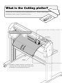
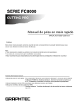
What is the Cutting plotter?
A machine that cuts the drawing, which was produced by the PC, through the Media (paper,
Marking film) without using the Cutter knife or Scissors.
Operation of Cutting plotter
Tool carriage
Media
The Media is fed back and forth, the tool moves the
Cutter from side to side, and the Tool carriage moves
up and down, so that the Media can be cut.
Tool carriage
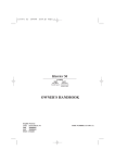
*To avoid bodily injury, handle cutter blades with care.
Blade length adjustment knob
Adjust the blade
length by turning
the Blade length
adjustment knob.
Cutter plunger
The Cutter plunger is mounted on the Tool carriage
during use. The Cutter blade is mounted on the Cutter
plunger.
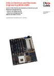
Paper
Plotting pen (Water-based fiber pen)
Backing sheet
Using the plotting pen instead of a cutter allows
the drawing and illustration to be generated.
Use it for testing before cutting.
Adjust the blade length to such a
degree that the trace of blade can
be made on the backing sheet.
Media
The media includes the film, paper and etc. Select it depending on the application.
Marking film
Sticker
using the Cutter
[STRUCTURE OF MARKING FILM]
Marking
film
Paste
Backing sheet
Paper (Roll media)
Drawing and illustration using the PEN
Pattern paper
cutting out the cut line
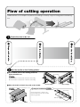
Flow of cutting operation
Introduced here as an example is the process for making a sticker by using the Cutting plotter and Marking
film.
1
Create the data to be cut.
3 Set the Condition.
2 Set the Media.
1 Prepare the data.
2
Set the media on the Cutting plotter.
aCheck which point on the Cutting plotter the
paper should be set.
P.1-5
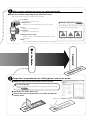
Stock rollers
When Stock roller is mounted at front of main unit : Front loading
When Stock roller is mounted at rear of main unit : Rear loading
bPlace the media on Stock tray, and set the media.
(*The illustration shows the rear loading as a case.)
P.2-6
<Front loading>
Setting the Push Roller
<Rear loading>
P.2-13
Push rollers
Fix the push rollers so that they are
positioned above both ends of media
and also grit rollers.
Grit rollers
3
Make various settings necessary for cutting the media.
lSet the tool conditions depending on the media to be used.
*This function allows each preset condition to be memorized.
Tool setting :
Set the type of tool to be used.
Setting the Force :
Adjust the force for holding down the tool on the media.
Speed :
Adjust the tool moving speed.
Acceleration :
Adjust the tool moving speed.
Adjusting the Blade Length :
Adjust the length of cutter blade protruded out of the Cutter
pen plunger.
Offset :
Adjust the distance between cutter blade edge and center of Plunger.
Running Cutting Tests
Run Cutting tests after making each setting,
and check actual cutting conditions.
Offset is small
Proper
Output the created data into the Cutting plotter, and cut the media.
aOutput the data into the cutting plotter same as printer.
To stop on the way
Plotting operation will stop temporality when [STOP] key is pressed during
plotting.
P.3-12
bCut off the cut media. (Cross cut)
cRemove the unnecessary portion of cut media, and affix the
transfer sheet.
Transfer sheet
Completed
4 Cut the Media.
4
P.2-34
Offset is large
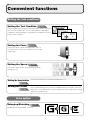
Convenient functions
Setting the tool conditions
Setting the Tool Condition
P.2-24
The tool setting allows 8 settings numbered from 1 to 8 to be memorized.
First select this condition No. to set the tool conditions. Switching the
condition No. allows plotting to run immediately according to the preset
8 types of tool conditions.
Setting the Force
P.2-29
This function allows cutting and plotting force to be set.
Set it with reference to the tool conditions for each media
and tool type.
Setting the Speed
P.2-28
This function allows the tool speed (moving speed) for
plotting to be set.
Setting the Acceleration
This function allows the acceleration for plotting to be set.
P.2-30
Setting the Offset
P.2-26
Corrects the offset of center point for betaken blade edge and plunger depending
on the cutter blade types to be used. The standard values are already set when the
blade name is selected. Besides, sensitive adjustment can be made within ± 5 range
against the standard value.
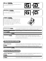
Area option
Enlarging/Shrinking
P.4-8
Enlarging/shrinking for plotting can be set.
Mirror
P.4-6
This function allows the reversing for plotting origin point
and coordinate axes to be set.
Rotation
P.3-10
This function allows the rotation for the plotting origin
point and coordinate axes to be set.
ARMS
P.5-2
A function to scan the registration mark written on the
media using sensors. The axis tilting, distance and 2
axes warp adjustment can be adjusted, besides this
function makes possible for a precise cutting when
cutting the borders of the images printed by the printer
or when cutting the media again.
Plotting range
Set the plotting range arbitrarily. Also the origin point moves according to the
plotting range. It is impossible to plot at outside of the preset range.
P.4-2
Extension of plotting range
P.4-4
width
Set the Increase/Decrease of plotting range based on the default value (edge at
inside of push roller).
Setting the cut line pattern
Set whether cutting is made using the solid or dotted line (cut line).
P.7-15
Manually adjust the position of the media and tool, specify the position of the
registration marks (adjustment marks), and adjust the tilting of the axes and
distance. When impossible to read the registration marks through the ARMS, the
precision for both cutting the borders of the images plotted by different plotter and
re-cutting the media can be improved.
Manual positioning
P.6-3
adjustment
Environmental setting
Two types of settings can be saved independently. Two-preferred sets of setting
can be stored separately if there are 2 operators, or 2 different settings for different
media can be stored, making a quick change when the media is switched.
Dual configuration
P.4-12
Apparel (AP) Mode
P.4-14
Used when this Plotter is used in combination with CAD targeted for Apparel.
Setting the Plotting quality
Distance adjustment
P.7-13
Tangent Emulation
P.7-2
Corrects the deviation in the length of cut or plotted line segments, which occurs
depending on the type or thickness of media being used.
Set it when cutting the thick media. Use this function when the blade tip gets sunk
into the media, making the blade hard to rotate so that, the start/end points are not
consistent or the corner does not get a sharp angle.
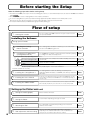
Before starting the Setup
Make the following preparations before starting Setup.
¯A
ssemble the FC8000, and set up it. For the assembling procedures, see either Manual attached to the Stand or FC8000 User's Manual
(PDF). P.1-5
¯W
hen the previous version of Cutting Master 2 was installed, uninstall it.
¯T
o use the Cutting Master 2, previously install the Design application (Adobe Illustrator or Corel Draw) that is used.
¯W
hen there are virus detection program or system resident program, terminate them beforehand.
¯T
o install, the Administrator (as Administrators group member) shall log on.
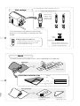
Flow of setup
For each software of FC8000 install them using the Installer housed in
the attached CD-ROM.
P.09
Installing the Cutting
2.
Plotter Controller
Once Cutting Plotter Controller is installed, you can control main
functions of FC8000 through the PC.
P.09
Installing the FC8000 Driver
3.
(Cutting Plotter Driver)
The FC8000 Driver software controls the Plotter and makes plotting
according to the data created by the PC.
P.10
1. Starting the Installer
Installing the Software
Setting up the FC8000
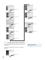
The procedures vary depending on the Interface.
Selection
To connect using the USB
Turn on the power source of Plotter in the middle of installing, and connect
the USB cable.
P.11
To connect using the Network
cable
Input the IP address of FC8000.
P.12
To connect using the RS-232C
Connect the RS-232C cable after installing is finished.
P.13
*Network (LAN) interface is a factory-installed option. It can not be retrofitted.
Install the software as necessity.
4. Installing the Cutting Master 2
The Cutting Master 2 allows the drawing created by the PC
application (Adobe Illustrator, CorelDRAW) to be directly output into
the Plotter.
P.13
5. Installing the User's Manual
Copy the User's Manual housed in the attached CD-ROM into the PC.
If you read User's Manual of CD-ROM as is or read it after printing, no
need to copy.
P.14
6. Installing the Adobe Reader
Required to read the User's Manual housed in the attached CD-ROM.
When already installed in your current PC, no need to newly install.
P.15
Setting up the Plotter main unit
1. Setting the media (paper)
Fix the media to the Plotter.
P.16
2. Setting the Plotter
Set the Plotter depending on the type of media.
P.18
3. Attaching the Tool
The cutter blade can replaced depending on the material or
thickness of the media.
P.19
4. Tool adjustment and test cutting
Adjust the protruded cutter edge length and the cutting Force
depending on the material and thickness of the media. Make test
cutting for the set media to adjust the best condition.
P.19
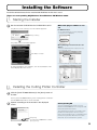
Installing the Software
Install the software housed in the attached CD-ROM into the PC that is used.
[Types of corresponding OS]:Windows Vista/Windows XP/Windows 2000
1. Starting the Installer
1 Set the attached CD-ROM into the CD-ROM Drive of PC.
The [User account control] screen of software appears.
When auto play of software is not
set
For Windows Vista :
1.Select [Run MultiSetup.exe] from [Autoplay]
Selection menu of Windows.
Click [Continue].
The [Start] screen of Installer appears.
When [Autoplay] Selection menu does not
appear :
1.Select the CD-ROM Drive from Computer, and select
[Open] with right clicked.
Start Button of Install
2.Select the [MultiSetup.exe], and double click it.
To start installing for each software, click the start button of the
Install displayed on the screen.
*Also for Windows XP/2000, take the same
manner.
2.Installing the Cutting Plotter Controller
Click the [Install FC8000 Software] in the [Start] screen of
1 Installer.
For the [Install FC8000 Software], both "Cutting Plotter Controller"
and "FC8000 Plotter Driver" will be installed.
Operate according to the instruction in the displayed
2 screen.
Click [Next].
*To install only FC8000 Driver Software,
press [Cancel].
Corresponding PC
To use the Cutting Plotter Controller, use PC of
Windows Vista/XP/2000 and connect using the USB/
LAN (Network)/RS-232C Interface.
The Cutting Plotter Controller is the software, which
provides the similar operation as that of control
panel of Plotter through the PC. If your Windows and
Interface being used are different from the above
mentioned, use the Control panel to operate.
Click [Next].
Click [Next].
Click [Finish].
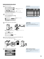
3.Installing the FC8000 Plotter Driver
Once installing of Cutting Plotter Controller is terminated, the
install screen of FC8000 Plotter Driver appears.
1 Operate according to the instruction in the screen.
Click [OK].
Click [OK].
Click [OK].
10
CAUTION
Do not connect the Interface cable between Plotter
(FC8000) and PC before installing the FC8000
Plotter Driver.
To connect using the USB cable
2 Select the Interface.
Port name
1 Select "USB" from Pull
down list.
Select the "Port name" depending on the Interface
that is used.
Interface
To connect using the USB cable
2 Click the [OK].
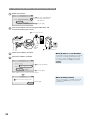
The procedures vary depending on the selected Interfaces.
3
To connect using the Network
cable
To connect using the RS-232C
cable
Install the Driver software.
To output the data for plotting into the
file without connecting to the plotter
Port
Next
name
procedure
USB
P.11
TCP/IP
P.12
COM1
P.13
FILE
-
* Network (LAN) interface is a factory-installed
option. It can not be retrofitted.
2 Click the [Install].
1 Click the [CHECK BOX].
4 Connect the Power cable of Plotter.
CAUTION
Be sure to ground the earth terminal.
If the plotter is not grounded, the operator could
suffer an electric shock in the event of current
leakage.
1Check that the Plotter power
source is turned off (the "u" side
is pressed down).
2Connect the power source
cable.
Click [OK].
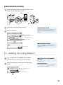
Connect the Plotter to the PC using the USB cable, and
5 turn
on the Plotter power source.
2 Connect it to the PC
1 Connect it to the
Plotter.
USB cable
3 Press Power switch "|".
6 The Device Driver will be installed.
When normally installed
"Start" → "Control panel" → "Hardware and Sound"
→ "Graphtec FC8000" appears on "Printer". (For
Windows Vista)
11
To connect using the Network cable (Factory-installed option)
2 Select the Interface.
1 Select the "Standard TCP/
IP Port: (Network)" from
Pull down list.
2 Click the [OK].
Connect the Plotter to the PC using the USB cable, and
3 turn
on the Plotter power source.
2 Connect it to the PC
1 Connect it to
the Plotter.
Network
hub
Network
cable
3 Press Power switch "|".
4 Check the IP address of Plotter.
5 Input the IP address of Plotter.
When IP address is not identified
The IP address may vary depending on the network
environment. Consult with Network administrator.
For how to check the IP address of this machine,
see "Setting Interface" in FC8000 User's Manual.
P.9-2
1 Input the IP address.
2 Click the [OK].
The IP address on the screen is only for reference.
When normally installed
Click [OK].
12
"Start" → "Control panel" → "Hardware and Sound"
→ "Graphtec FC8000" appears on "Printer". (For
Windows Vista)
To connect using the RS-232C cable
Connect the Plotter to the PC using the RS-232C cable,
2 and
turn on the Plotter power source.
2 Connect it to the PC
1 Connect it to
the Plotter.
RS-232C cable
3 Press Power switch "|".
3 Check the machine for RS-232C setting.
4 Select the Interface.
Setting the port of PC
When RS-232C is used to connect, the port setting
for between PC and this machine should be
matched. For the port setting with PC, see Help in
Windows.
1 Select "COM1:
(Communication port)"
from Pull down list.
2 Click the [OK].
When normally installed
Click [OK].
"Start" → "Control panel" → "Hardware and Sound"
→ "Graphtec FC8000" appears on "Printer". (For
Windows Vista)
4. Installing the Cutting Master 2
If you use Illustrator or CorelDRAW, click the [Setup
1 Cutting
Master 2] on the "Start" screen of Installer.
When Illustrator or CorelDRAW is
not used
No need to install
Operate according to the instruction in the displayed
2 screen.
For the Macintosh
See User's Manual contained in each language
folder inside attached CD-ROM.
1 Select "English" from Pull
down list.
2 Click the [OK].
13
Click [Next].
Click [Next].
Click [Next].
Click [Next].
Click [Yes].
Click [Yes].
Click [Finish].
Click [Next].
Click [Next].
5. Installing the User's Manual
Click the [Install User's Manual] on the "Start" screen of
1 Installer.
Operate according to the instruction in the displayed
2 screen.
Click [Next].
14
When already installed
No need to install
Click [Finish].
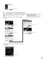
6. Installing the Adobe Reader 6
1 Click the [Adobe Reader] on the "Start" screen of Installer.
Operate according to the instruction in the displayed
2 screen.
When already installed
When Adobe Acrobat or Reader is already used in
your PC being used, no need to install.
Click [Next].
Click [Install].
Click [Next].
Click [Finish].
Click [Next].
Click [Exit] on "Start" screen of Installer to terminate all
3 installing.
Click [Exit].
15
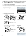
Setting up the Plotter main unit
1. Setting the media (paper)
For the FC8000, the roll media and sheet media can be used. The feeding method includes rear loading (feeding
from rear side) and front loading (feeding from front side). Select it depending on the assembled way of Plotter.
If the roll media is used
Media
Explained here is the operation method that is used for rear loading. For use in
front loading, see the column shown at right.
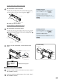
The setup methods vary depending on the media
type, width and loading method. See the page
stated in the "Next procedure" of the following
conditions table.
Media
Media width
type
1 Lower the Media set lever to raise the push rollers.
Media sensor
Loading
Next
method
procedure
Roll
160 to 540mm
F/R
P.17
media
540mm or over
F/R
P.17
Sheet
100 to 160mm
F/R
P.18
media
160mm or over
F/R
P.18
For front loading
Media set lever
Push roller
Media set lever
1 Lower the
Media set
lever.
The Stock tray is mounted at front side.
Once the Media set lever is lowered, "LOAD
MEDIA!" appears on LCD.
2 Insert the media through the bottom of push roller.
Raise the Media lock, (1), put the roll media so that the extracted
portion faces up (2), and extract the media to such a degree that it
covers the top of media sensor. (3)
For front loading
Media lock
Media lock
Media sensor
1 Raise the Media lock
(lock).
2 Put the Roll media on
the Media bracket.
3 Extract the Media.
Media bracket
Media lock
16
A stopper, which is used to prevent the stock rollers
from rotating when setting the roll media. The media
lock ensures that the media is pulled straight out
from the roll.
When the media width is 160 to 540 mm
3 Set the positions of two push rollers.
Push both ends of media so that it comes over the media sensor, and
set the push rollers so that they comes over the grit rollers. (1) Move the
push rollers, that are not used, to the Shunting position. (2)
Push roller
Standby position
For the standby position, see "Standby of Push
P.2-13
Roller" in FC8000 User's Manual.
Position of Push roller
For the adjustment of Push roller position, see
"Aligning the Push Roller" in FC8000 User's Manual.
Push roller
P.2-13
Media
Grit roller
Media sensor
After setting, go to the procedure 4.
When the media width exceeds 540 mm
3 Set the positions of three push rollers.
Push both ends and center of the media so that it comes over the media
sensor, and set the push rollers so that they comes over the grit rollers.
(1) Move the push rollers, that are not used, to the Shunting position. (2)
Standby position
For the standby position, see "Standby of Push
P.2-13
Roller" in FC8000 User's Manual.
Position of Push roller
Push roller
For the adjustment of Push roller position, see
"Aligning the Push Roller" in FC8000 User's Manual.
P.2-13
Media
Grit roller
Media sensor
Take up the slack of roll media, and fix it with the Push
4 rollers.
For front loading
Media lock
Media set lever
2 Raise the Media set lever.
Media
set
lever
1 Pull the edge to take up the slack.
3 Lower the Media
lock (Cancel).
The MEDIA FEEDING METHOD
SELECTION screen appears.
If the sheet media is used
Lower the media set lever to raise the Push rollers. (See "If
1 the
roll media is used".)
Insert the media through the bottom of Push roller. (See "If
2 the
roll media is used".)
17
When the media width is 100 to 160mm
3 Set the positions of two Push rollers.
Standby position
Push both ends of media so that it comes over the top of Media sensor,
and position the Push rollers while the left edge of grit roller is being set
as the starting point so that the Push roller come over the lengthy grit
rollers at right edge. (1) Move the Push rollers, that are not used, to the
Shunting position. (2)
Origin point
Push roller
1Set the Media and
Push rollers on the
lengthy Grit roller.
Media sensor
2 Move away the Push
roller that is not used.
Media
For the standby position, see "Standby of Push
P.2-13
Roller" in FC8000 User's Manual.
Position of Push roller
For the adjustment of Push roller position, see
"Aligning the Push Roller" in FC8000 User's Manual.
P.2-13
When the media width exceeds
161mm
See "If the roll media is used".
Grit roller
Take up the slack of roll media, and fix it with the Push
4 rollers.
(See "If the roll media is used".)
2. Set the media type into the Plotter.
Set the media type into the Plotter depending on the preset media.
1 Select the type of the loaded media.
To change the loading method
Use the keys numbered [1] to [4] of Control panel to select.
Roll media
Plot starting with the edge of media.
[1]
Plot starting with the preset position.
[2]
Sheet media
[3]
When similar media is reset
[4]
Once the media is set, the next screen appears.
It is set to rear loading in the initial setting. If setup
was made according to Front loading, change the
loading method. For the change of loading method,
see "Setting Feeding Method" in FC8000 User's
P.2-19
Manual.
Display of "CONTINUE"
Depending on the status of Plotter, the fourth option
"CONTINUE" may appear.
The MEDIA FEEDING METHOD
SELECTION screen appears.
To reset the similar media and to continue the same
setting as is during plotting, select the "CONTINUE".
It appears when Media set lever is raised/lowered
after setting the media.
Wait until the Plotter detects the media size and setting
2 completes.
Once completed, the next screen appears.
"READY" appears.
This screen is called as "Ready status".
18
Ready status
The "READY" appears on LCD when PC data
receiving enabling status is achieved in Plotter.
When power source of main unit is turned on, the
screen after version displayed is called "DEFAULT
SCREEN".
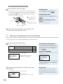
3. Attaching the Tool
Attach a tool (cutter pen, plotter pen) to the Plotter. It is explained here using cutter pen as an example.
1 Loosen the Tool holder screw.
2 Attach the tool on the Tool holder.
While pushing the Tool holder in the upward direction, push the tool all
the way into the holder until its flange contacts the upper part of the Tool
holder.
Upper part of
Tool holder
For half cutting
Flange (innermost side: Tool 1)
CAUTION
Do not touch the Tool edge when power is turned on
or or during operation.
CAUTION
When pushing the Tool holder with your fingers, the
blade tip may be protruding. Take care not to cut
your fingers.
Half cutting and Cutting out
The cutting operation is different depending on the
position of Tool holder where the Tool is inserted.
Mainly, the forward side is used for Cutting out, and
innermost side is for Half cutting.
For Cutting out and Half cutting, see "Attaching a
P.2-4
Tool" in FC8000 User's Manual.
For cutting out (forward side: Tool 3)
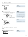
3 Fix the Tool.
CAUTION
Make sure that the Tool bracket is engaged on the tool's flange, and
then tighten the screw.
Flange
Do not over tighten the screw during fixing. When
the screw is loosened and disconnected, connect it
again.
The pouncing pen (option) should be connected on
the Tool 1 by all means.
Bracket to hold
tool
4. Tool adjustment and test cutting
After setting the Tool/Speed/Force/Acceleration, make test cutting, and repeat until optimal condition is
achieved.
1 Press the [CONDITION] key in the Default screen.
CAUTION
Do not touch the Tool edge when power is turned on
or or during operation.
CONDITION screen (1/3) appears.
19
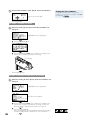
2 Set the Tool conditions (Tool, Speed, Force, Acceleration).
eg.) Screen for Tool setting
Setting the Tool conditions
For detailed setting methods of each plotting
condition, see "Selecting Tool conditions" in FC8000
P.2-24
User's Manual.
Press the [ENTER].
To make 1 cut with set value
Make test cutting for one piece while Tool conditions are
3 being
set.
CONDITION screen (1/3) appears.
1 Press the POSITION [◄] key.
2Press the POSITION (▲▼◄►) key so that the Tool carriage moves
to the location you wish to perform the test cutting.
Tool carriage
Press the [ENTER] key.
To make 3 cuts with set value and ±1 of set value
Make test cutting for three pieces while Tool conditions are
3 being
set.
CONDITION screen (1/3) appears.
1 Press the POSITION [►] key.
CUT TEST screen appears.
2Press the POSITION (▲▼◄►) key so that the Tool carriage moves
to the location you wish to perform the test cutting. (See the case
when test cutting is made for the preset value or one piece)
3Press the [1] key (FORCE).
Three cut test patterns, where the FORCE increased/decreased by 1
each time is added, will be cut with a focus on the current Force.
20
-1
Set value
+1
4Press the [ENTER] key after completion.
Go back to the TEST CUT MENU screen.
5Press the [2] key (CUTTER OFFSET).
Three cut test patterns, where the Offset value increased/decreased by
1 each time is added, will be cut with a focus on the current Offset value.
6Press the [ENTER] key.
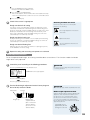
4 Check if the cut test is appropriate.
Rough standard of half cutting
Peel off the corners of the triangle(s). Ideally, only slight traces of the
cutter blade should remain on the backing sheet. If the backing sheet
has been cut through, either the FORCE setting is too high or the cutterblade tip is extended too far. If the backing sheet shows only a few
traces of the cutter blade, either the FORCE setting is too low or the
cutter blade tip is not sufficiently extended.
Rough standard of cutting out
Ideally, the backing sheet should be cut out completely. If the backing
sheet is not completely cut, either the FORCE setting is too low or the
cutter blade tip is not sufficiently extended.
Rough standard of Plotting Pen
Adjust the speed so there will be no faint lines. To prolong the pen life,
set the FORCE to the lowest setting.
Checking methods for offset
Check if the offset value is set correctly with
reference to the following.
ot enough adjustment. Increase the
N
offset value.
Optimal offset value.
oo much adjustment. Decrease the
T
offset value.
5 Repeat the setting and test cutting until optimal cut is achieved.
Blade adjusting function
To set the optimal blade length, test cutting should be done several times. This function enables the blade
length to be easily adjusted.
1 Control the panel according to the following procedures.
Press the [CONDITION] key in the Default screen.
CAUTION
Do not touch the Tool edge when power is turned on
or or during operation.
CONDITION screen (1/3) appears.
Press the POSITION [▲]key.
Press the [4] key (BLADE ADJUST).
Turn the Blade length adjustment knob of Cutter plunger to
2 the
left to fully retract the blade.
Cutter blade
Plunger-cap
Plunger
CAUTION
To avoid bodily injury, handle cutter blades with care.
Blade length adjustment knob
Blade length
adjustment knob
(Blue : For 0.9 mm
diameter blades)
(Red : For 1.5 mm
diameter blade)
Adjust the blade length by turning the Blade length
adjustment knob. To protrude the blade, turn in
the direction of "A". To retract the blade, turn in
the direction of "B". When the knob is turned by
one scale unit, the blade moves approximately
0.1 mm. One full turn of the knob moves the blade
approximately 0.5 mm.
Cutter blade moves
approximately 0.1 mm
turning one scale unit
B
A
21
3 Control the panel according to the following procedures.
Press the [ENTER] key.
BLADE LENGTH setting screen appears.
Press the [1] key (BLADE LENGTH TARGET).
BLADE LENGTH TARGET screen appears.
CAUTION
When the [1] key (BLADE LENGTH TARGET) is
pressed, the Tool carriage will start moving, so take
care not to cut your fingers.
Press the POSITION [▲▼] key to increase or decrease the setting value.
It will get set and return to BLADE LENGTH setting screen by pressing
the POSITION [◄] key (PREVIOUS).
Press the [2] key (CHECK).
CAUTION
The amount and direction for turning the
adjustment knob are displayed.
When the [2] key (CHECK) is pressed, the Tool
carriage will start moving, so take care not to cut
your fingers.
Turn the Blade length adjustment knob to adjust the cutter
4 blade
length.
Current blade length is displayed by pressing the [2] key
(CHECK), so adjust the blade length until it matches the
thickness of the media.
Press the [3] key (END).
Press the [CONDITION] key.
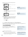
4. Actual cutting using the "Cutting Master 2".
The procedures for actual cutting are explained here using the data created by the Design application. Try it
after the setup for the Plotter and PC has been completed.
Preparation
You should previously finish assembling of "FC8000 Cutting
Plotter", connecting with PC, and installing of Design
application ("CorelDRAW" or "Adobe Illustrator") and "Cutting
Master 2". See "Flow of Setup".
The "Cutting Master 2" is compatible with the
following Design software. Install the Design
software before installing the "Cutting Master 2".
(Windows)
Corel CorelDRAW 10/11/12/X3
Adobe Illustrator 8/9/10/CS/CS2/CS3
(Macintosh)
Adobe Illustrator 10/CS/CS2/CS3
1 Plotting using the Design application.
Create the design using the corresponding Design application.
Give attention to the points shown at right during creating the
design. There are also other points that should be taken account
in creating the design. For the detail, see "Guide line for creating
the design" in Help file of "Cutting Master 2".
22
Precautions in creating the design
The bit-mapped image cannot be used. It should be
transformed into Vector object.
Do not use Pattern painting, Bit-mapped painting,
Lens effect and other customized paintings.
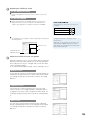
2 Displaying the CUT/PLOT screen
For the Adobe Illustrator
1Select "Cutting Master 2" from "File" menu, and then select "CUT/
PLOT".
For the CorelDRAW
1Select "CUT/PLOT" from Corel Application Launcher.The Corel
Application Launcher is the list inside the Standard tool bar. It
enables other applications to start from inside the CorelDRAW.
Icons of CorelDraw
The following icons are used for each version of
CorelDraw.
CorelDRAW 10
CorelDRAW 11
CorelDRAW 12 & X3
2The CUT/PLOT screen appears, and the Job (Design) created by the
Illustrator appears.
Preview screen
To adjust the point to be cut, drag the Job on
Preview screen.
If difficult to see the Job due to its small size, click
"DISPLAY OF ALL OBJECTS" button. All objects
inside design are zoomed/reduced so that they fall
within the Preview window.
Job
"DISPLAY OF ALL
OBJECTS" button
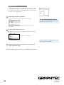
3 Actions that CUT/PLOT screen can perform
Using the CUT/PLOT screen, not only that the data is output into
Plotter, but also that media and job size can be changed, data
to be output by each layer is changed, and several same data
can be copied and output.
To set more detailed output methods, use the following screens.
Normal screen
It is possible to change the media and job (created design) size
and position, besides plural same can be output. For the detail,
see "Setting the property of normal tab" in Help file of "Cutting
Master 2".
Layering screen
It is possible to set various parameters for each layer and
color. For instance, the setting that allows cutting speed to be
changed for each layer, can be established. For the detail, see
"Setting the property of layer tab" in Help file of "Cutting Master
2".
Split screen
One job can be split into plural small tiles before outputting,
besides outputting part of them can be stopped. For the detail,
see "Setting the property of split tab" in Help file of "Cutting
Master 2".
23
Detail screen
It is possible to change the cutting sequence, besides to read
the Registration Mark for which printing was already finished on
the media. For the detail, see "Setting the property of detail tab"
in Help file of "Cutting Master 2".
4 Outputting into Plotter and plotting
Press the "Send" button at lower right of CUT/PLOT screen.
To stop during plotting (cutting)
To temporarily stop plotting during operation, press
[STOP] key of the plotter main unit.
The job will be added into Job window, and be output into Plotter
sequentially.
5 Cut off the cut media (Cross cut).
1Make sure that the Plotter is in ready status, and press the [CROSS
CUT] key on Control panel.
CROSS CUT screen appears.
2Press the [1] key (CUT).
The media will be cross-cut.
It will return to DEFAULT SCREEN without cross cut
by pressing the [2] key (CANCEL).
Remove the unnecessary portion of the cut media, and
6 attach
the Transfer sheet.
For the detailed usage of main unit, see FC8000 "User's Manual".
24
621409900