1
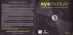
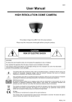
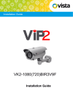
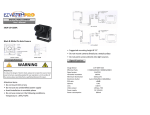
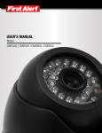
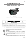
296Z
USER MANUAL
High Resolution Dome Camera
The product image may differ from the actual product.
Please read the instructions thoroughly before using the product.
FEATURES
1.
2.
3.
4.
5.
High resolution for clearer and sharper images
High sensitivity in the dark environment, 0.1 Lux / F2.0, 0Lux (IR ON)
Day and night features for 24-hour surveillance
Excellent image quality
IR LED effective range reaches up to 15 meters
PACKAGE CONTENT
IR camera with a power and video cable * 1
User Manual * 1
SPECIFICATIONS*
IR Camera
IR Dome Camera
Pick up Element
1/3" H.R. Color CCD image sensor
Number of Pixel
771(H) x 492(V) <NTSC> / 753(H) x 582(V) <PAL>
Resolution
Minimum illumination
IR LED
IR Effective Range
520 TV Lines
0.1 Lux / F2.0, 0Lux (IR ON)
21 units
Up to 15 Meters
S/N Ratio
More than 48dB (AGC OFF)
Electronic Shutter
1/60 (1/50) to 1/100,000 sec.
Lens
f3.6mm / F2.0
Lens Angle
92.6˚
IRIS Mode
AES
White Balance
ATW
Video Output
1.0Vp-p composite, 75Ω
Power Source (±10%)
Current Consumption (±10%)
Dimensions (mm)
* The specifications are subject to change without notice.
DC12V
70mA (IR OFF), 220mA (IR ON)
94.1(Θ) x 70.7(H)
** Dimensional Tolerance: ± 5mm
K133E_V1.1
INSTALLATION
1.
Open the packet and select the location where you would like to install the dome camera. Take the mounting bracket
off the dome camera.
2.
Slightly drill the supplied three screws into the three round holes on the mounting bracket and rotate the bracket
clockwise until the screws are wedged into the narrower chase (as shown in Figure 1). Tighten the fixing screws to
secure the mounting bracket to the ceiling.
3.
Drill a hole in the middle circle and let the power and video line go through (as shown in Figure 2).
1.
Mount the dome body onto the mounting bracket and rotate it until it clicks to secure (as shown in Figure 3). Adjust
the camera to the correct position and test the dome camera to make sure it is working properly.
Figure 1
Figure 2
Figure 3
CONNECTION
1.
DC12V Input Terminal
Connect the power terminal of the camera to a 12V DC regulated power supply.
Note: Please use the correct power adaptor, DC12V (regulated), to operate this unit.
The power tolerance of this unit is DC12V ± 10%. Over maximum DC 12V power input will damage this unit.
2.
Video Output Connector (VIDEO OUT)
Connect the camera video output and the monitor video input with 75Ω coaxial cable.
CAUTION
RISK OF ELECTRIC SHOCK
CAUTION:
To reduce the risk of electric shock, do not expose this apparatus to rain or moisture.
Only operate this apparatus from the type of power source indicated on the label.
The company shall not be liable for any damages arising out of any improper use, even if we have been advised of the possibility of such
damages.
The lightning flash with arrowhead symbol, within an equilateral triangle, is intended to alert the user to the presence of
uninsulated “dangerous voltage” within the product’s enclosure that may be of sufficient magnitude to constitute a risk of
electric shock to persons.
This exclamation point within an equilateral triangle is intended to alert the user to the presence of important operating and
maintenance (servicing) instructions in the literature accompanying the appliance.
ROHS Announcement
All lead-free products offered by the company comply with the requirements of the European law on the Restriction of
Hazardous Substances (RoHS) directive, which means our manufacture processes and products are strictly “lead-free”
and without the hazardous substances cited in the directive.
The crossed-out wheeled bin mark symbolizes that within the European Union the product must be collected seperately at
the product end-of-life. This applies to your product and any peripherals marked with this symbol. Do not dispose of these
products as unsorted municipal waste.
CE Mark
This apparatus is manufactured to comply with the radio interference.
The company does not warrant that this manual will be uninterrupted or error-free. We reserve the right to revise or remove
any content in this manual at any time.