1
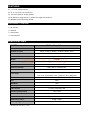
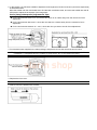
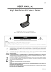
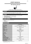
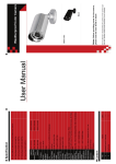
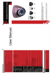
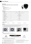
518Z USER MANUAL High Resolution IR Camera Series The product image may differ from the actual product. Please read the instructions thoroughly before using the product. alarm shop CAUTION RISK OF ELECTRIC SHOCK CAUTION: To reduce the risk of electric shock, do not expose this apparatus to rain or moisture. Only operate this apparatus from the type of power source indicated on the label. The company shall not be liable for any damages arising out of any improper use, even if we have been advised of the possibility of such damages. The lightning flash with arrowhead symbol, within an equilateral triangle, is intended to alert the user to the presence of uninsulated “dangerous voltage” within the product’s enclosure that may be of sufficient magnitude to constitute a risk of electric shock to persons. This exclamation point within an equilateral triangle is intended to alert the user to the presence of important operating and maintenance (servicing) instructions in the literature accompanying the appliance. ROHS Announcement All lead-free products offered by the company comply with the requirements of the European law on the Restriction of Hazardous Substances (RoHS) directive, which means our manufacture processes and products are strictly “lead-free” and without the hazardous substances cited in the directive. The crossed-out wheeled bin mark symbolizes that within the European Union the product must be collected separately at the product end-of-life. This applies to your product and any peripherals marked with this symbol. Do not dispose of these products as unsorted municipal waste. CE Mark This apparatus is manufactured to comply with the radio interference. Warning This is a class A product. In a domestic environment this product may cause radio interference in which case the user may be required to take adequate measures. The company does not warrant that this manual will be uninterrupted or error-free. We reserve the right to revise or remove any content in this manual at any time. 167_V0.9 FEATURES (1) 1/3" H.R. Image sensor (2) f3.8 ~ f9.5mm vari-focal lens (3) 700 TVL superior image quality (4) IR effective range up to 15 meters for night surveillance (5) Weather-proof housing design PACKAGE CONTENT IR camera Bracket Desiccants User Manual SPECIFICATIONS* MODEL IR Vari-focal Camera Pick-up Element 1/3" H.R. Color CCD image sensor Number of Pixels 976(H) x 494(V) <NTSC> / 976(H) x 582(V) <PAL> 700 TVL Resolution alarm shop 0.1 Lux; 0 Lux (IR ON) Min. Illumination IR LED 17 units Up to 15 meters IR Effective Range S/N Ratio More than 48dB (AGC OFF) 1/60 (1/50) to 1/100,000 sec. Electronic Shutter f3.8mm ~ f9.5mm Lens Lens Angle Wide: 71.4° (Horizontal) / 52° (Vertical) / 92.8° (Diagonal) Tele: 31.8° (Horizontal) / 23.9° (Vertical) / 39.8° (Diagonal) White Balance ATW AGC Auto IRIS Mode AES IP Rating IP66 Video Output Operating Temperature Power Source (±10%) Current Consumption (±10%) Dimensions (mm)** Net Weight (g) * The specifications are subject to change without notice. ** Dimensional Tolerance: ± 5mm 1.0 Vp-p composite, 75Ω -10˚C~40˚C DC12V 70mA(IR OFF), 220mA (IR ON) 97(Ø) × 60(H) 300 INSTALLATION 1. Use the supplied three screws to attach and fix the bracket to wall. 2. Remove the Joint Lock from the bracket by turning it counterclockwise. Then, connect the Joint Lock to the backside of the camera (turn clockwise). NOTE: There are two screw holes on the backside of the camera. Please choose the proper one which best suits your installation environment. 3. Connect the camera with the Joint Lock connected to the bracket. After that, secure the Joint Lock to fix. Figure 1 Figure 2 Figure 3 4. Connect the camera video output to DVR’s video input with a 75Ω coaxial cable. Then, connect the camera to power with a DC 12V power supply. 5. After installation, please follow the next section below to start selecting focal length and adjusting focus. For further camera angle change, the tilt angle of the camera is limited to 30 degrees and the right/left pan angle is limited to 15 degrees each. NOTE: Please use the correct power adaptor, DC12V (regulated), to operate this unit. The power tolerance of this unit is DC12V ± 10%. Over maximum DC 12V power input will damage this unit. alarm shop NOTE: To ensure the camera has sufficient protection against moisture, an extra waterproof measure, such as by using an insulating tape, must be used to cover the power and video connectors after connection. FOCAL LENGTH SELECTION AND FOCUS ADJUSTMENT NOTE: The appropriate temperature for focal length selection and focus adjustment is 0˚C ~ 40˚C. 1. Rotate the front cover to remove it. Note: The camera front cover must be removed for focal length selection and focus adjustment: Please finish focal length selection and focus adjustment ASAP and replace the front cover back as described in the following steps. Please prevent doing this in the high moisture environment. If it’s inevitable, please finish it ASAP. 2. In the camera, you’ll find two handles to adjust the focal length (from f3.8mm to f9.5mm) and focus respectively, as illustrated below. Move the handle near the main board first to find the best surveillance area, and move the handle near the IR LED panel to adjust the sharpness of the image later. Focus (Image Sharpness) Adjustment Tips: For the environment below 15°C, aim at the view which is 15 meters away from the camera for focus adjustment. For the environment above 35°C, aim at the view which is 5 meters away from the camera for focus adjustment. For the environment between 15 ~ 35°C, aim at the view you want to see for focus adjustment. 3. Find the desiccants supplied in the sales package, and place them into the camera as shown below. NOTE: Please finish step 4 ~ 5 in 10 minutes in case the desiccants absorb too much moisture before the installation is completed and are unable to keep the air dry in the camera anymore. alarm shop 4. Replace the front cover. NOTE: Make sure the front cover is fastened well. 5. Slide to mount the shield on the camera.