1
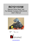
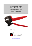
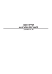
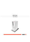
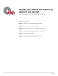
RCY21151
Manual Crimp Hand Tool
For Minitek Contacts AWG 26-30
User’s Manual
Revision
Date
: 02
: August 14, 2007
www.foehrenbach.be
1. Purpose
Crimping of Minitek AWG 26-30 contacts onto dedicated stranded wire.
2. Tool description
-
Cat. No.: RCY21151
-
Single head crimp tool. The tool crimps one contact per cycle.
-
Short set-up times.
-
Releasable ratchet ensures the complete crimping process.
-
Ergonomically handles for comfortable working.
-
Optimal force transmission ratio.
-
The hand tool features a terminal guide that accepts Minitek contacts on a
regular carrier strip. During each crimping cycle, the tool separates the
contact in process from the carrier strip.
The tool kit consists of:
-
The hand tool
-
This user’s manual
-
A plastic protection case
-
Tool release key size 6 – 7 (DIN 895)
RCY21151 User’s Manual
Date: August 14, 2007
Page 2/11
Rev.: 02
www.foehrenbach.be
3. Selecting the wire size
Be sure that the tool is open. If not, close the handles until the ratchet releases.
Further you must open the handles of the tool.
The crimper of this hand tool has two crimping areas. Each of which is
applicable to a different range of wire. The crimping area can easily be
selected by following the following procedure.
Unlock the set screw as shown in the picture.
Remove the rod.
The crimper has marks showing AWG size applicable each crimping area.
For the selection of the appropriate crimping area, please refer to the table.
RCY21151 User’s Manual
Date: August 14, 2007
Page 3/11
Rev.: 02
www.foehrenbach.be
Terminal
P/N
Wire range
AWG (mm²)
77138-001
#26 -#28
(0.13–0.08)
#28-#30
(0.08-0.05)
Wire barrel
Width
Height
(mm)
(mm)
0.600.65
1.0
0.570.62
Ins. Barrel
Width Height
(mm)
(mm)
1.5
MAX
1.4
MAX
Crimp
strength (kg)
1.2 MIN
0.7 MIN
According to your application, position the crimper with the selected crimping
area towards the anvil.
Position the rod with the flattened side behind the set screw.
Lock the set screw.
RCY21151 User’s Manual
Date: August 14, 2007
Page 4/11
Rev.: 02
www.foehrenbach.be
4. The process
Be sure that the tool is open. If not, close the handles until the ratchet releases.
Further you must open the handles of the tool.
Insert a strip of contacts (cut to the proper length) into the terminal guide of the
tool.
Take care that the insulation crimp area of the contacts are properly positioned
into the appropriate slot of the terminal guide.
Feed a terminal into the crimping area of the hand tool. Take care that the
carrier strip of the terminals is guider in the slot of the cutter.
As shown on the picture, insert a stripped and straightened wire into the wire
barrel of the terminal.
Make sure that the stripped length of the wire is in the range of 1.2 to 2.2 mm.
Be careful not to make cuts or nicks in the strands during the stripping
operation.
The use of improperly prepared wire may cause insufficient crimp
performance obtained.
RCY21151 User’s Manual
Date: August 14, 2007
Page 5/11
Rev.: 02
www.foehrenbach.be
Whilst keeping carefully the wire in position, close the handles until the ratchet
releases.
Open the tool and take the crimped wire.
The tool cuts during each crimping cycle one part of the terminal carrier strip.
RCY21151 User’s Manual
Date: August 14, 2007
Page 6/11
Rev.: 02
www.foehrenbach.be
Before making the next crimp, feed terminal by one pitch.
5. Adjustments
-
The tool is adjusted by Föhrenbach Application Tooling engineers. In order to
maintain the performance of the tool, don’t carry out any adjustments.
-
During the life time of the tool, it could be possible that the ‘index’ position of
the contacts has to be adjusted. A spring loaded device is gripping into the
feeding holes of the contact strip. As such, you get a feed back (feeling) if the
contact is slide in position. Turning the screw counter clock wise will reduce
the feeling. Turning the screw too much clock wise, will block the contact strip.
This is not good!
-
For any support, please contact Föhrenbach Application Tooling:
Föhrenbach Application Tooling
Krijgsbaan 128
B – 2640 Mortsel
Belgium
Tel
Fax
e-mail
Website
RCY21151 User’s Manual
Date: August 14, 2007
: +32 (0)3 216 19 98
: +32 (0)3 216 15 07
: [email protected]
: www.foehrenbach.be
Page 7/11
Rev.: 02
www.foehrenbach.be
6. General specifications
-
Colour
Weight
Size (protective box)
: Black metal with red levers.
: 1,3 kg
: l: 265 mm x w: 230 mm x h: 53 mm
7. Input material and functional requirements
7.1. Wire
-
Stranded wire dedicated for the mentioned contacts. AWG 26-30 (0.13 – 0.05
mm2).
7.2. Components
- Minitek contacts type 77138-001.
8. Process output
-
Due to the manual process, the output capacity is highly depended on the
skills of the operator.
9. Safety and ergonomics
-
Apply the tool only for the target as mentioned in chapter 1. Purpose.
-
For operator safety, it’s necessary to apply eye protection.
-
Apply the tool only in a dry and clean environment.
-
Apply the tool only in a well lighted environment (1000 Lux).
-
Only skilful operators who are trained by Föhrenbach Application Tooling
engineers are allowed to apply the tool.
RCY21151 User’s Manual
Date: August 14, 2007
Page 8/11
Rev.: 02
www.foehrenbach.be
-
In normal operation, the hand tool can only be opened after a complete
closing cycle. In order to open the tool before completing the entire crimp
cycle, turn the release handle, by means of the release key (DIN 895), in the
clock wise direction.
10. Environmental conditions
10.1. Ambient temperature
The ambient temperature is measured at a height of 1.5 m above the floor.
a.
b.
c.
Normal range
Average value
Maximum variation within a 5 min. period
: + 15 to +30°C
: ± 23°C
: ± 5°C
10.2. Humidity
a.
b.
Normal range (no condensation)
Range not resulting in constantly
reduced operation
: 40 to 70% R.H.
: 10 to 90% R.H.
10.3. Atmospheric pressure
Normal range: 533 - 1060 m bar.
11. Power connections
11.1. Electrical
No electrical supply required.
11.2. Pneumatic
No air supply required.
RCY21151 User’s Manual
Date: August 14, 2007
Page 9/11
Rev.: 02
www.foehrenbach.be
12. Warranty
Please refer to our Terms and Conditions of Sale.
13. Spare parts
-
wire crimp
insulation crimp
anvil wire crimp
anvil insulation crimp
RCY21151 User’s Manual
Date: August 14, 2007
: RCY21151A2
: RCY21151A3
: 411218
: 411220
Page 10/11
Rev.: 02
www.foehrenbach.be
Appendix A: Crimp conditions
The wire specified by UL-1007 (AWG # 26-#30) or equivalent wires shall be
crimped in accordance with the following conditions.
No.
Terminal
P/N
Wire range
AWG (mm²)
77138-001
#26 -#28
(0.13–0.08)
#28-#30
(0.08-0.05)
2
3
4
Item
Bend up
Bend down
Twist
Rolling
Bell mouth
Cut off tab length
Exceeded conductor length
5
Seam
1
Wire strip length (REF.)
Wire barrel
Width
Height
(mm)
(mm)
0.600.65
1.0
0.570.62
Ins. Barrel
Width Height
(mm)
(mm)
1.5
MAX
1.4
MAX
Crimp
strength (kg)
1.2 MIN
0.7 MIN
Requirement
3° MAX
3° MAX
3° MAX
8° MAX
0.1 – 0.4 mm
0 – 0.3 mm
0 – 0.8 mm
No evidence of seam opening. No strands exist out
of wire barrel.
1.2 - 2.2mm
Appendix B:
In order to apply the mentioned Minitek contacts, Föhrenbach Application
Tooling provides also mini-applicators and other dedicated semi-automatic
equipment.
The technical data in this publication has been carefully checked and assembled. No liability from inaccuracies or errors is assumed. The right
to change or improve this document without notice is reserved.
RCY21151 User’s Manual
Date: August 14, 2007
Page 11/11
Rev.: 02
www.foehrenbach.be