1
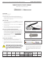
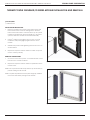
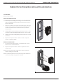
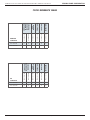
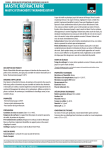
ASSEMBLY, INSTALLATION, AND REMOVAL OF
CONTACTS AND MODULES
FOR THERMOCOUPLE CONTACTS AND MODULES
Table of Contents
SECTION 1 RECEIVER CONTACT ASSEMBLY INSTRUCTIONS
SECTION 2 ITA CONTACT ASSEMBLY INSTRUCTIONS
SECTION 3 CONTACT INSTALLATION AND REMOVAL INSTRUCTIONS
SECTION 4 MODULE INSTALLATION AND REMOVAL INSTRUCTIONS
SECTION 5 CROSS REFERENCE TABLES
SECTION 6 PRODUCT PERFORMANCE SPECIFICATIONS
11/24/09
VIRGINIA PANEL CORPORATION
THERMOCOUPLE CONTACTS AND MODULES USER’S MANUAL: SECTION 1
THERMOCOUPLE RECEIVER CONTACT ASSEMBLY
PART # 610 113 131 / 610 113 132
TOOLS REQUIRED
Crimp Tool, Part # 910 101 102
Locator, Part #910 104 134
NOTE: Thermocouple contacts should be used in pairs with K Type
Thermocouple wire. 610 113 131 is Chromel and should be used with
the yellow or positive wire and 610 113 132 is Alumel and should be
used with the red or negative wire.
CRIMP TOOL SETUP
Set up the Crimp Tool, Part # 910 101 102 (Figure A), by loosening
the latch locking screw. Turn counter-clockwise to loosen. Remove
any previously used locator.
1.
Insert the open end of the Locator, Part # 910 104 134 (Figure B),
into the locator retainer.
2.
3.
RETAINING LATCH ASSEMBLY
AND LOCKING SCREW
LOCATOR
RETAINER
MICROCRIMP
ADJUSTING KNOB
Slide the retaining latch toward the locator until the locator is
securely locked into place. Tighten the latch locking screw.
MICROCRIMP
INDICATOR
CRIMP TOOL ADJUSTMENT AND WIRE PREPARATION
1.
Adjust the crimp tool setting by pulling the microcrimp adjusting
knob and turning it at the same time (clockwise increases, counterclockwise decreases setting) until the desired setting is achieved
on the microcrimp indicator (Table 1). Verify with pin gauge. For
more information about gauge pins, visit vpc.com/gaugepins. See
calibration instructions for Part # 910 101 102/103 for pin gauge
verification instructions.
2.
Strip wire to the appropriate length (Table 1).
Figure B. Locator, Part # 910 104 134.
CONTACT SETUP AND CRIMPING
1.
Figure A. Crimp Tool, Part # 910 101 102.
Insert the contact into the crimp tool and squeeze the handle
slightly to hold the contact in position for wire insertion.
2.
INSPECTION HOLE
SHRINK TUBING
Insert stripped wire fully into the contact and squeeze the crimp
tool handle until a positive stop is reached. The tool will release and
return into a fully “open” position. Remove crimped contact and
wire.
OBSERVE PRECISION RATCHET ACTION BY OPENING
AND CLOSING CRIMP TOOL FULLY SEVERAL TIMES.
NOTE THAT TOOL CANNOT BE OPENED WITHOUT
COMPLETING A CYCLE. NEVER ATTEMPT TO
DISASSEMBLE TOOL. NEVER TIGHTEN OR LOOSEN STOP
NUTS ON BACK OF TOOL.
Figure C. Final assembled contact.
3.
VPC recommends applying 0.093” [2.40 mm] diameter
shrink tubing, 0.625” [16 mm] long to all Thermocouple
crimps. The shrink tubing should be applied over the
larger diameter on the rear of the contact, as shown
(Figure C).
Table 1. Crimp Settings.
CONTACT
610113131
610113132
1-1
CRIMP TOOL
910101102
LOCATOR
DIE
910104134
STRIP LENGTH
(IN [MM])
WIRE GAUGE
CRIMP SETTING (IN [MM])
MAX
MIN
0.250
[6.35]
20
0.047 [1.19]
0.046 [1.17]
24
0.033 [0.84]
0.029 [0.74]
For more information visit vpc.com
PULLOUT FORCE
(LBS [N])
EXTRACTION
TOOL
10
[44.5]
910110102
11/24/09
VIRGINIA PANEL CORPORATION
THERMOCOUPLE CONTACTS AND MODULES USER’S MANUAL: SECTION 2
THERMOCOUPLE ITA CONTACT ASSEMBLY
PART # 610 113 133 / 610 113 134
TOOLS REQUIRED
Crimp Tool, Part # 910 101 102
Locator, Part #910 104 135
NOTE: Thermocouple contacts should be used in pairs with K Type
thermocouple wire. 610 113 133 is Chromel and should be used with
the yellow or positive wire and 610 113 134 is Alumel and should be
used with the red or negative wire.
CRIMP TOOL SETUP
1.
Set up the Crimp Tool, Part # 910 101 102 (Figure A), by loosening the
latch locking screw. Turn counter-clockwise to loosen. Remove any
previously used locator.
2.
Insert the open end of the Locator, Part # 910 104 135 (Figure B), into
the locator retainer.
3.
Slide the retaining latch toward the locator until the locator is
securely locked into place. Tighten the latch locking screw.
RETAINING LATCH ASSEMBLY
AND LOCKING SCREW
LOCATOR
RETAINER
MICROCRIMP
ADJUSTING KNOB
CRIMP TOOL ADJUSTMENT AND WIRE PREPARATION
1.
Adjust the crimp tool setting by pulling the microcrimp adjusting
knob and turning it at the same time (clockwise increases, counterclockwise decreases setting) until the desired setting is achieved
on the microcrimp indicator (Table 1). Verify with pin gauge. For
more information about gauge pins, visit vpc.com/gaugepins. See
calibration instructions for Part # 910 101 102/103 for pin gauge
verification instructions.
MICROCRIMP
INDICATOR
Figure A. Crimp Tool, Part # 910 101 102.
Strip wire to the appropriate length (Table 1).
2.
CONTACT SETUP AND CRIMPING
Figure B. Locator, Part # 910 104 135.
1.
Insert the contact into the crimp tool and squeeze the handle
slightly to hold the contact in position for wire insertion.
2.
Insert stripped wire fully into the contact and squeeze the crimp
tool handle until a positive stop is reached. The tool will release and
return into a fully “open” position. Remove crimped contact and
wire.
INSPECTION HOLE
OBSERVE PRECISION RATCHET ACTION BY OPENING
AND CLOSING CRIMP TOOL FULLY SEVERAL TIMES. NOTE
THAT TOOL CANNOT BE OPENED WITHOUT COMPLETING
A CYCLE. NEVER ATTEMPT TO DISASSEMBLE TOOL.
NEVER TIGHTEN OR LOOSEN STOP NUTS ON BACK OF
TOOL.
SHRINK TUBING
Figure C. Final assembled contact.
3.
VPC recommends applying 0.093” [2.40 mm] diameter
shrink tubing, 0.625” [16 mm] long to all Thermocouple
crimps. The shrink tubing should be applied over the
larger diameter on the rear of the contact, as shown
(Figure C).
Table 1. Crimp Settings.
CONTACT
610113133
610113134
2-1
CRIMP TOOL
910101102
LOCATOR
DIE
STRIP LENGTH
(IN [MM])
WIRE GAUGE
910104135
0.250
[6.35]
CRIMP SETTING (IN [MM])
MAX
MIN
20
0.047 [1.19]
0.046 [1.17]
24
0.033 [0.84]
0.029 [0.74]
For more information visit vpc.com
PULLOUT FORCE
(LBS [N])
EXTRACTION
TOOL
10
[44.5]
910110102
11/24/09
VIRGINIA PANEL CORPORATION
THERMOCOUPLE CONTACTS AND MODULES USER’S MANUAL: SECTION 3
THERMOCOUPLE RECEIVER CONTACT INSTALLATION AND REMOVAL
PART # 610 113 131 / 610 113 132
TOOLS REQUIRED
5
/64 Allen Wrench
Phillips Head Screwdriver (for iCon Modules)
Thermocouple Receiver/ITA Extraction Tool, Part # 910 110 102
CONTACT INSTALLATION INSTRUCTIONS
1.
Assemble the contact to the respective wire.
NOTE: For more information concerning the process of crimping the
contact please see contact assembly instructions in Section 1 of this User’s
Manual.
2.
Insert the assembled contact into the back (wiring side) of the assembled
module (Figure A). The contact can only go into one side. Push the
contact forward. Once in place, pull the wire slightly to ensure that the
contact is seated.
CONTACT REMOVAL INSTRUCTIONS
1.
Remove the module from the receiver frame.
NOTE: For more information concerning the process of removing the
module from the receiver frame, see module installation and removal
instructions in Section 4 of this User’s Manual.
2.
Use a 5/64 Allen wrench or Phillips head screwdriver to remove the two 2-56
screws located at the top and bottom of the module (Figure B).
3.
Grasp the module halves and apply force in opposite directions, rocking
the ends of the module while slightly pulling the top of the module away
from the mating bottom section. Be sure to open both sides of the module
simultaneously or contacts could be damaged.
4.
Place the Thermocouple Receiver/ITA Extraction Tool, Part # 910 110 102,
over the contact to be removed/replaced (Figure C). Use care to keep
the tool perpendicular to the surface of the module, otherwise the tool or
the contact could be bent.
5. Once the extraction tool is seated and the retaining ring tabs on the
contact are compressed, push the tool into the module. The contact will
be pushed out of the rear of the module.
Figure A. Contacts inserted into the module.
MODULE MOUNTING
SCREW
MODULE MOUNTING
SCREW
2-56 SCREW
2-56 SCREW
Figure B. Open both sides of the module
simultaneously or pins could be damaged.
EXTRACTION TOOL
DO NOT PUSH THE TOOL INTO THE MODULE UNTIL THE TIP OF
THE EXTRACTION TOOL HAS FULLY SEATED INTO THE MODULE
AND COMPRESSED THE RETAINING RING TABS ON THE
CONTACT.
6.
7.
On the opposite side of the module from the extraction tool, grasp the
contact and hold it while removing the extraction tool. This will prevent
the contact from being pulled back into the module while the tool is
being removed.
A
Replace the module cap using both hands to push the separated
halves together. Replace and tighten the module retaining screws to a
maximum torque of 2 in-lbs [0.23 Nm].
NOTE: The process shown here uses standard/90 Series modules. The same
process is used for modules from other series.
NOTE: If you are using a hybrid module, you may need to reference the User’s
Manual for the other contact type for extraction instructions.
3-1
DETAIL A
Figure C. Ensure that the tool is kept perpendicular
to the module face to avoid damage to the contact
or tool.
For more information visit vpc.com
11/24/09
THERMOCOUPLE CONTACTS AND MODULES USER’S MANUAL: SECTION 3
VIRGINIA PANEL CORPORATION
THERMOCOUPLE ITA CONTACT INSTALLATION AND REMOVAL
PART # 610 113 133 / 610 113 134
TOOLS REQUIRED
Thermocouple Receiver/ITA Extraction Tool, Part # 910 110 102
CONTACT INSTALLATION INSTRUCTIONS
1.
Assemble the contact to the respective wire.
NOTE: For more information concerning the process of crimping the
contact please see contact assembly instructions in Section 2 of this
User’s Manual.
2.
Insert the assembled contact into the back (wiring side) of the
assembled module (Figure A). Push the contact forward. Once in
place, pull the wire slightly to ensure that the contact is seated.
CONTACT REMOVAL INSTRUCTIONS
1.
Remove the module from the ITA frame.
NOTE: For more information concerning the process of removing the
module from the ITA frame, see module installation and removal
instructions in Section 4 of this User’s Manual.
2.
Place the Thermocouple Receiver/ITA Extraction Tool, Part # 910 110
102, over the contact to be removed/replaced (Figure B). Use care
to keep the tool perpendicular to the surface of the module as not to
bend the tool or the contact to be removed. Rotate the tool slightly
while pushing it into the counter bore on the mating side of the
module.
3.
Once the extraction tool is seated properly and the retaining ring
tabs on the contact are compressed, push the tool into the module.
The contact will be pushed out of the rear of the module.
Figure A. Contacts inserted into the module.
EXTRACTION TOOL
DETAIL A
DO NOT PUSH THE TOOL INTO THE MODULE UNTIL THE TIP
OF THE EXTRACTION TOOL HAS BEEN FULLY SEATED INTO
THE MODULE AND COMPRESSED THE RETAINING RING
TABS ON THE CONTACT.
4.
On the opposite side of the module from the extraction tool, grasp
the contact and hold it while removing the extraction tool. This will
prevent the contact from being pulled back into the module while
the tool is being removed.
Figure B. Ensure that the tool is kept perpendicular to the
module face to avoid damage to the contact or tool.
NOTE: The process shown here uses standard/90 Series modules. The
same process is used for modules from other series.
NOTE: If you are using a hybrid module, you may need to reference the
User’s Manual for the other contact type for extraction instructions.
3-2
For more information visit vpc.com
11/24/09
THERMOCOUPLE CONTACTS AND MODULES USER’S MANUAL: SECTION 4
VIRGINIA PANEL CORPORATION
THERMOCOUPLE STANDARD/90 SERIES MODULE INSTALLATION AND REMOVAL
TOOLS REQUIRED
3
/32 Allen Wrench
INSTALLATION INSTRUCTIONS
1.
Place the module in the receiver or ITA until the upper and
lower module screws touch the mating holes in the inner
frame. Ensure that Position 1 is located at the top for systems
in which the modules are oriented vertically or to the left for
systems in which the modules are oriented horizontally.
2.
Using a 3/32 Allen wrench, tighten the top screw 1 to 2 full
revolutions, while pushing lightly against the face of the
module.
3.
Maintain this pressure while tightening the bottom screw 1 to
2 full revolutions.
4.
Repeat this sequence until the module is seated. Torque the
screw to 4 in-lbs [0.45 Nm].
POSITION 1
REMOVAL INSTRUCTIONS
1.
To remove, loosen the top screw 1 to 2 full revolutions. Loosen
bottom screw 1 to 2 full revolutions.
2.
Repeat this sequence until the module is separated from the
receiver or ITA.
Figure A. Receiver Module.
NOTE: Push or pull the module evenly from the top and bottom to
prevent damage to the module.
NOTE: For optimum performance and system longevity, distribute
the contact load evenly throughout the module.
Figure B. ITA Module.
4-1
For more information visit vpc.com
11/24/09
VIRGINIA PANEL CORPORATION
THERMOCOUPLE CONTACTS AND MODULES USER’S MANUAL: SECTION 4
THERMOCOUPLE ICON MODULE INSTALLATION AND REMOVAL
TOOLS REQUIRED
Phillips Head Screwdriver
INSTALLATION INSTRUCTIONS
NOTE: The receiver strain relief plate or the ITA cover may need to be
removed prior to installing or removing an iCon module. Please
refer to the appropriate User’s Manual for instructions on how to
perform these steps.
1.
Place the module in the receiver or ITA until the upper and lower
module screws touch the mating holes in the inner frame. Install
modules such that Position 1 is located at the top of the ITA/
receiver frame.
2.
Using a Phillips head screwdriver, tighten the top screw 1 to 2 full
revolutions, while pushing lightly against the face of the module.
3.
Maintain this pressure while tightening the bottom screw 1 to 2 full
revolutions.
4.
Repeat this sequence until the module is seated. Torque the
screw to 1.5 in-lbs [0.16 Nm].
REMOVAL INSTRUCTIONS
1. To remove, loosen the top screw 1 to 2 full revolutions. Loosen
bottom screw 1 to 2 full revolutions.
2.
Figure A. Receiver Module.
Repeat this sequence until the module is separated from the
receiver or ITA.
NOTE: Push or pull the module evenly from the top and bottom to
prevent damage to the module.
NOTE: For optimum performance and system longevity, distribute the
contact load evenly throughout the module.
Figure B. ITA Module.
4-2
For more information visit vpc.com
11/24/09
5-1
ICON
MODULE
CRIMP TOOL
LOCATOR
EXTRACTION
510 161 110
910 101 102
910 104 135
910 110 102
STANDARD/
90 SERIES ITA
MODULES
510 108 245
ITA
CONTACTS
510 108 124
ICON
MODULE
CRIMP TOOL
LOCATOR
EXTRACTION
510 160 110
910 101 102
910 104 134
910 110 102
STANDARD/
90 SERIES
RECEIVER
MODULES
510 104 261
RECEIVER
CONTACTS
510 104 133
THERMOCOUPLE CONTACTS AND MODULES USER’S MANUAL: SECTION 5
610 113 131
X
X
X
X
X
X
610 113 132
X
X
X
X
X
X
610 113 133
X
X
X
X
X
X
610 113 134
X
X
X
X
X
X
For more information visit vpc.com
VIRGINIA PANEL CORPORATION
CROSS REFERENCE TABLES
11/24/09
VIRGINIA PANEL CORPORATION
THERMOCOUPLE CONTACTS AND MODULES USER’S MANUAL: SECTION 6
THERMOCOUPLE CONTACT ELECTRICAL SPECIFICATIONS
[21.59]
0.85
[23.11]
0.91
[2.67]
ø.11
[2.67]
ø.11
Receiver Contact
Part # 610 113 131
ITA Contact
Part # 610 113 133
Dimensions shown: [millimeters]
inches
Electrical Specifications
ANSI TYPE
K
TC TEMPERATURE RANGE
Chromel® and Alumel®
-200ºC to 1250ºC
EMF
-5.97 to +50.63 mV
POLARITY
Chromel® +
Alumel® _
Mechanical Characteristics
CYCLE LIFE
20,000
MATING FORCE
4 oz [0.11 kg]
OUTER SHIELD
Base
THERMOCOUPLE PAIR MATERIALS
Chromel® and Alumel®
Material
6-1
For more information visit vpc.com
11/24/09