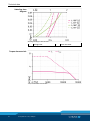
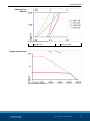
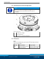
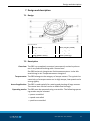
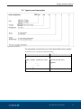
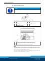
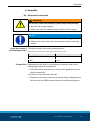
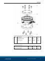
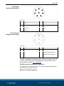
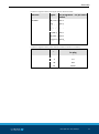
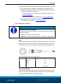
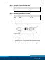
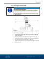
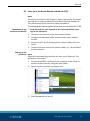
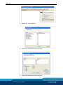
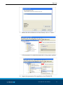
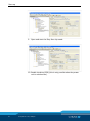
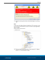
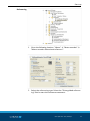
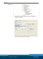
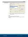
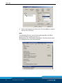
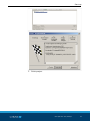
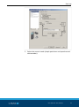
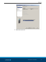
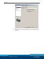
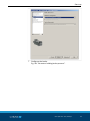
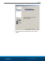
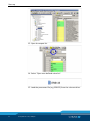
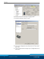
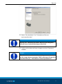
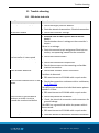
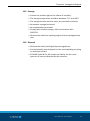
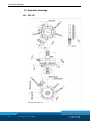
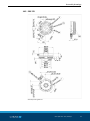
1
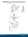
Translation of Original Operating Manual Electric rotary module ERS 135 - 210 / 560V Assembly and Operating Manual Superior Clamping and Gripping Imprint Imprint Copyright: This manual remains the copyrighted property of SCHUNK GmbH & Co. KG. It is solely supplied to our customers and operators of our products and forms part of the product. This documentation may not be duplicated or made accessible to third parties, in particular competitive companies, without our prior permission. Technical changes: We reserve the right to make alterations for the purpose of technical improvement. Document number: 0389064 Edition: 01.07 |13/04/2015|en © SCHUNK GmbH & Co. KG All rights reserved. Dear customer, congratulations on choosing a SCHUNK product. By choosing SCHUNK, you have opted for the highest precision, top quality and best service. You are going to increase the process reliability of your production and achieve best machining results – to the customer's complete satisfaction. SCHUNK products are inspiring. Our detailed assembly and operation manual will support you. Do you have further questions? You may contact us at any time – even after purchase. Kindest Regards Yours SCHUNK GmbH & Co. KG Spann- und Greiftechnik Bahnhofstr. 106 – 134 D-74348 Lauffen/Neckar Tel. +49-7133-103-0 Fax +49-7133-103-2399 [email protected] www.schunk.com 2 01.07|ERS 135 - 210 / 560V|en Table of Contents Table of Contents 1 About this manual .................................................................................................... 5 1.1 Warnings ................................................................................................................... 5 1.2 Applicable documents .............................................................................................. 6 2 Basic safety notes .................................................................................................... 7 2.1 Intended use ............................................................................................................. 7 2.2 Not intended use ...................................................................................................... 7 2.3 General safety notes ................................................................................................ 7 2.4 Ambient conditions and operating conditions......................................................... 9 2.4.1 Electromagnetic compatibility ...................................................................... 9 2.4.2 Environmental conditions ........................................................................... 11 2.5 Personnel qualification ........................................................................................... 13 2.6 The use of personal protective equipment ............................................................ 13 2.7 Notes on particular risks......................................................................................... 14 3 Warranty ................................................................................................................. 18 4 Scope of delivery ..................................................................................................... 19 5 Accessories .............................................................................................................. 19 6 Technical data ......................................................................................................... 20 6.1 Basic Data ............................................................................................................... 20 6.1.1 Data ERS 135 560V ...................................................................................... 20 6.1.2 Data ERS 170 560V ...................................................................................... 23 6.1.3 Data ERS 210 560V ...................................................................................... 26 6.2 SCHUNK power and sensor cable ........................................................................... 29 6.3 Optional holding brake ........................................................................................... 29 6.4 Pneumatic/electrical feed-through option ............................................................ 30 6.5 IP54 version ............................................................................................................ 30 7 Design and description ............................................................................................ 31 7.1 Design ..................................................................................................................... 31 7.2 Description ............................................................................................................. 31 7.3 Mechanische Schnittstellen ................................................................................... 32 7.4 Electrical interfaces ................................................................................................ 32 7.5 Type key and name plate ....................................................................................... 33 7.6 Optional holding brake ........................................................................................... 34 8 Assembly ................................................................................................................. 35 8.1 Mechanical connection .......................................................................................... 35 8.2 Electrical connection .............................................................................................. 38 01.07|ERS 135 - 210 / 560V|en 3 Table of Contents 8.3 Optional holding brake ........................................................................................... 42 8.3.1 Electrical connection ................................................................................... 43 8.3.2 Dismantling micro valve .............................................................................. 44 8.3.3 Installing and connecting the micro valve .................................................. 45 8.3.4 Realigning the connection cable ................................................................. 47 9 Start-up ................................................................................................................... 48 9.1 Start-up of the Bosch Rexroth IndraDrive C/CS ..................................................... 49 9.2 Start-up of the Siemens Sinamics S120 CU310/CU320 .......................................... 58 9.3 Inbetriebnahme des ERS mit einem beliebigen Umrichter ................................... 79 10 Control parameters ................................................................................................. 80 10.1 Bosch Rexroth IndraDrive C/CS-Basic setting ........................................................ 80 10.2 Siemens Sinamics S120 - series .............................................................................. 81 11 Trouble shooting ..................................................................................................... 85 11.1 ERS dreht sich nicht ................................................................................................ 85 11.2 ERS has regulation difficulties ............................................................................... 86 11.3 ERS oscillates .......................................................................................................... 86 11.4 Bearing noise .......................................................................................................... 86 11.5 Error message for the winding temperature ......................................................... 87 12 Maintenance and care ............................................................................................. 88 12.1 Maintenance and lubrication intervals .................................................................. 88 12.2 Module Servicing .................................................................................................... 89 12.3 Modul zerlegen ....................................................................................................... 89 13 Transport, storage and disposal ............................................................................... 90 13.1 Transport ................................................................................................................ 90 13.2 Packaging ................................................................................................................ 90 13.3 Storage .................................................................................................................... 91 13.4 Disposal................................................................................................................... 91 14 Assembly drawings .................................................................................................. 92 14.1 ERS 135 ................................................................................................................... 92 14.2 ERS 170 ................................................................................................................... 93 14.3 ERS 210 ................................................................................................................... 94 15 Translation of original declaration of incorporation ................................................ 95 15.1 Annex to Declaration of Incorporation .................................................................. 96 4 01.07|ERS 135 - 210 / 560V|en About this manual 1 About this manual This instruction is an integral part of the product and contains important information for a safe and proper assembly, commissioning, operation, maintenance and help for easier trouble shooting. Before using the product, read and note the instructions, especially the chapter "Basic safety notes". 1.1 Warnings To make risks clear, the following signal words and symbols are used for safety notes. DANGER Danger for persons. Non-compliance will inevitably cause irreversible injury or death. WARNING Dangers for persons. Ignoring a safety note like this can lead to irreversible injury and even death. CAUTION Dangers for persons. Non-observance can cause minor injuries. NOTICE Material damage Information about avoiding material damage. WARNING Warning about dangerous electrical voltage WARNING Warning about hot surfaces 01.07|ERS 135 - 210 / 560V|en 5 About this manual 1.2 Applicable documents • General terms of business • Catalog data sheet of the purchased product • Assembly and Operating manuals of the accessories • SCHUNK CD with: – Parameterfiles for controller Bosch Rexroth IndraDrive C/CS – Parameterfiles for controller Siemens Sinamic S 120 CU310DP and S 120 CU320-DP The documents listed here, can be downloaded on our homepage www.schunk.com 6 01.07|ERS 135 - 210 / 560V|en Basic safety notes 2 Basic safety notes 2.1 Intended use The product was designed to rotate loads, workpieces and objects. The poduct may only be operated in combination with a controller. The product is intended for installation in a machine/system. The requirements of the applicable guidelines must be observed and complied with. The product may be used only in the context of its defined application parameters ( 6, Page 20). The product is designed for industrial use. To use this unit as intended, it is also essential to observe the technical data and installation and operation notes in this manual and to comply with the maintenance intervals. 2.2 Not intended use Use which is not specified as an intended use is for instance when the product is for example used as a pressing tool, stamping tool, lifting tool, guide for tools, cutting tool, tensioning mean, boring tool. 2.3 General safety notes • Observe these safety notes and supplementary instructions for use prior to starting work with the product. • Carefully read through all the documents supplied before starting up or using the product. • Please refer to the documentation for the connecting and installing conditions and the technical data and restrictions and observe these at all times. Every person called upon by the operator to work on the product must have read and understood the complete assembly and operating manual. This applies in particular to occasional personnel, such as maintenance personnel. • The product may pose a danger, for instance in the following situations: – When the product is not used in accordance with its appropriate use. – When the product is not installed or maintained properly. – When the safety notes or assembly instructions are not observed. 01.07|ERS 135 - 210 / 560V|en 7 Basic safety notes • Avoid any manner of working that may interfere with the functioning and operational safety of the product. • Do not start up a damaged or faulty product. • Only use spare parts and accessories that have been authorized by SCHUNK. Leave the hardware components in their original state and do not manipulate them or the software without the express consent from SCHUNK. Additional bore holes, threads or attachments, that are not offered by SCHUNK as accessories, may impair the safety of the product and are only permitted with the approval of SCHUNK. • Error-free and safe operation of the product requires proper transportation and storage, observation of the assembly and installation regulations that apply to the product, as well as careful and responsible operation and servicing. • Improper handling of the product, failing to observe the safety notes and manipulating the maintenance products may damage the product and also cause serious injury. • A risk assessment must be created for the system or machine into which the product is to be installed. The operator must product monitoring strategies and superordinate measures for personal protection based on the risk analysis. In this the safety rules that apply to the entire system or machine must be taken into account. 8 01.07|ERS 135 - 210 / 560V|en Basic safety notes 2.4 Ambient conditions and operating conditions • The module may be used only in the context of its defined application parameters.( 6, Page 20). • Operate the procuct protected against splashes,, fumes, polltion and EMC influences. 2.4.1 Electromagnetic compatibility The module fulfills the requirements of the EMC law of the Single European Market. The devices passed the EMC test in accordance with the following standards: Standard Title EN 61000-6-2 (2006) EMC: Generic standard – Immunity in industrial environments EN 61000-6-3 (2011) EMC: Generic standard – Emission standard for residential and light industrial environments The EMC-compliant installation of the product and the use of interference resistant wiring are necessary for trouble-free operation. Interference variables: Pulsed interference variables: The following table shows the electromagnetic compatibility with respect to pulsed interference variables. Pulsed interference variable Tested with Corresponds to intensity Electrostatic discharge according to Air discharge: 8 kV EN 61000-4-2 (2008) Contact discharge: 4 kV 3 Burst pulse, fast transient Supply line: + - 2 kV interference variables according to On signal, data and control line: + -1kV EN 61000-4-4 (2008) 3 High-energy single pulse (surge) EN 61000-4-5 1 + - 500V, surge symmetrical, + - 500V, surge asymmetrical (length of lead > 30 m) 01.07|ERS 135 - 210 / 560V|en 9 Basic safety notes Sinusoidal interference variables: The following table shows the electromagnetic compatibility with respect to sinusoidal interference variables Sinusoidal interference variable Test values Correspo nds to intensity HF irradiation (electromagnetic fields) according to EN 61000-4-3 80 % amplitude modulation at 1kHz to 10 V/m in the range from 80 … 1000 MHz to 3 V/m in the range from 1.4 … 2 GHz to 1 V/m in the range from 2 … 2.7 GHz 3 HF energizing on lines and shields according to EN 61000-4-6 Test voltage 10 V with amplitude modulation 3 80 % of 1 kHz in the range from 150 kHz … 80 MHz Emission of radio The emission was tested according to EN 61000-6-3 and coninterference firmed. Wire conducted emission Value 0.15 … 0.5 MHz < 66 dB (µV) quasi peak, < 56 dB (µV) mean value 0.5 … 5 MHz < 56dB (µV) quasi peak, < 46 dB (µV) mean value 5 … 30 MHz < 60 dB (µV) quasi peak, < 50 dB (µV) mean value The following table shows the emission of electromagnetic fields according to EN 55011:2009, limit class A, group 1, measured at a distance of 10 m Interference variable Value 30 … 230 MHz < 30 dB (µV) quasi peak, measured at 10 m 230 … 1000MHz < 37 dB (µV) quasi peak, measured at 10 m 10 01.07|ERS 135 - 210 / 560V|en Basic safety notes 2.4.2 Environmental conditions Requirements for This product exceeds the requirements of IEC 61131-2:2007 with transport and storage respect to permissible environmental conditions. The following information applies if the product is transported and stored in the original package. Mechanical environmental conditions Standard: IEC 60721-3-2 (version 1. 3. 1997) Title: Classification of environmental conditions – Part 3: Classification of groups of environmental parameters and their severities, Section 2: Transportation. Class 2M2 applies. Climatic environmental conditions Standard: IEC 60721-3-2 (version 1. 3. 1997) Title: Classification of environmental conditions – Part 3: Classification of groups of environmental parameters and their severities, Section 2: Transportation. Class 2K4 applies. The aforementioned standards result in the following parameters for the essential environmental conditions. The information applies if the product is transported and stored in the original package. Environmental condition Value Note Free fall EN 60068-2-32 <= 0.3 m In the transport package: 5 g Temperature EN 60068-2-2 +70° C Test Bb, dry heat, storage Temperature EN 60068-2-1 -40° C Test Ab, cold, storage Temperature shock EN 60068-2-14 Test Na, holding time 3 h, 5 cycles -40 … +70° C Air pressure IEC 60068-2-13 1140 … 660 hPa Corresponds to an elevation of -1000 … 3500 m 01.07|ERS 135 - 210 / 560V|en 11 Basic safety notes Requirements during The following overview shows the permissible environmental conoperation ditions for the product. Mechanical environmental conditions Standard: IEC 60721-3-2 (version 1. 3. 1997) Title: Classification of environmental conditions – Part 3: Classification of groups of environmental parameters and their severities, Section 3: Stationary use at weatherprotected locations. Class 3M3 applies. Climatic environmental conditions Standard: IEC 60721-3-2 (version 1. 3. 1997) Title: Classification of environmental conditions – Part 3: Classification of groups of environmental parameters and their severities, Section 3: Stationary use at weather-protected locations. Class 3K3 applies The aforementioned standards result in the following parameters for the essential environmental conditions. Environmental condition Value Note Temperature EN 60068-2-2 +55° C Relative humidity 55 , non-condensing, dry heat, in operation Temperature EN 60068-2-1 0° C Cold, storage, in operation Temperature EN 60068-2-30 +25 … +55° C Humid heat, cyclic The product may be used at the following locations only if additional measures are taken: • locations with high content of ionizing radiation • locations with extreme operating conditions, such as caustic vapors, gases, oils or chemicals • systems requiring special monitoring, such as high-risk rooms In addition, the product is not approved for use in potentially explosive zones. If the product is subjected to excessively high jolts or vibrations, suitable measures must be taken to damp the amplitudes or accelerations of these interference factors. In such cases, use systems to damp or eliminate the vibrations. 12 01.07|ERS 135 - 210 / 560V|en Basic safety notes Tests under environ- Tests with respect to mechanical environmental conditions mental conditions The following table shows the type and scope of inspections for which the product was tested with respect to mechanical environmental conditions. Test Physical variable Vibrations EN 60068-2-6 Vibration (Version 2008) Frequency range Value, comment Sinus 5 … 500 Hz Deflection 10 mm 5 … 500 Hz Vibration acceleration 30 m/s2 Shock EN 60068-2-27 (Version 2009) Shock form Half-sine Peak acceleration 250 m/s2 Pulse duration 11 ms Number of shocks per direction 50 per axis Number of axes 3 2.5 Personnel qualification • Only qualified personnel may operate the product or work in its vicinity. • Personnel must be familiar with the required safety equipment, know how to use it and be trained in First Aid. • Work on the electrical installations shall only be performed by electricians or instructed personnel under the guidance and supervision of an electrician, and in accordance with the electrical standards. • Observe the national accident prevention regulations and the general safety notes. 2.6 The use of personal protective equipment When installing or removing the product, observe the relevant health and safety at work rules and use the required personal protective equipment (protective gloves, safety boots and safety goggles). 01.07|ERS 135 - 210 / 560V|en 13 Basic safety notes 2.7 Notes on particular risks General information • Observe safe distances. • Observe the minimum safety requirements for the use of equipment. • Never take maintenance product out of operation. • Install the provided protective product in the danger zone before switching the product on. • Remove the energy supplies before installation, modification, maintenance, or adjustment work. Ensure that no residual energy remains in the system. • Do not move parts by hand when the energy supply is connected. • Do not reach into the open mechanism or the movement area of the unit. • Perform maintenance, modifications, and additions outside the danger zone. • During all work, secure any product attached to controller against accidental operation. • Take particular care during maintenance and disassembly. • Only trained staff may perform disassembly work. Protection during handling and assembly • There is a risk of injury when handling the product incorrectly. Only trained staff may perform maintenance and assembly work. For all work, secure the product against accidental operation. • Observe the relevant accident prevention rules. • Use suitable assembly and transport equipment and take precautions to prevent jamming and crushing. 14 01.07|ERS 135 - 210 / 560V|en Basic safety notes Protection against dangerous movements Dangerous movements may be caused by faulty actuation of drives that are connected Dangerous movements may be caused by operating mistakes or faulty parameterization during start-up or by software errors. • Never rely merely on the response of the monitoring function to avert danger. Assume that the drive movement is faulty as long is the installed monitors are not effective, since the effect depends on the control and the current operating state of the drive. Perform maintenance, modification and attachment work outside of the danger zone defined by the movement range. • To avoid accidents and/or material damage, access to the movement area of the machine must be restricted. Restrict accidental access of persons in this area, e.g. by providing a protection cover, a protective fence or a photoelectric barrier. The protection cover and the protective fence must have sufficient stiffness to withstand the maximum possible movement energy. EMERGENCY STOP switches must be easily accessible. Before starting up the machine or system, check that the EMERGENCY STOP system is working. Prevent operation of the machine if this protective equipment does not function. Electric components • Work on the electrical installations shall only be performed by electricians or instructed personnel under the guidance and supervision of an electrician, and in accordance with the electrical standards. • Observe the general set-up and safety rules applicable when performing work on power plants. • Lay electric lines according to the rules of the profession, e.g. in a cable duct or a cable bridge. Observe cable laying standards. • Before connecting or disconnecting electric cables, switch off the power supply and check that lines are dead. Secure power supply against reactivation. 01.07|ERS 135 - 210 / 560V|en 15 Basic safety notes • Disconnect the product from the mains prior to commencing work on it and wait for at least 15 minutes for dangerous voltages to disappear (capacitor charge). Check that the product is deenergized before you start work. • Before switching on the product, check whether the protective conductor on all electric components has been installed correctly and according to the connection diagram. • Check whether covers and protective equipment have been attached to prevent touching live components. • Do not touch the connecting elements of the product, when the power supply is switched on. Magnetic and electromagnetic fields • Persons with pace-makers, metal implants, metal shards or hearing aids require the consent of a physician before entering areas in which components of the electric drive and control systems are mounted, started up and operated. • Persons with pace-makers, metal implants, metal shards or hearing aids required the consent of a physician before entering areas in which motor parts with permanent magnets are stored, repaired or assembled. • Do not operate high-frequency or radio products in the proximity of electric components of the drive system and their feed lines. If using such devices is necessary: Check the machine or system for possible failures when using such devices at different intervals and in different states of the control system when starting-up of the electric drive and control system. You may need to carry out an additional specific EMC control if the system's risk potential is high. Hot surfaces • Do not touch hot surfaces (e.g. brake resistors, heat sinks, drive units, windings and sheet packets). It may take up to one hour for some components to cool off after they have been switched off. If necessary, wear personal protective equipment (gloves). 16 01.07|ERS 135 - 210 / 560V|en Basic safety notes DANGER Risk of electric shock due to contact with live parts! • Before conducting work on the machine and the auxiliary equipment, disconnect them from the power supply and make sure they cannot be switched back on again. • Wait until the frequency controller is discharged. WARNING Risk of injury from objects falling and being ejected • The danger zone must be surrounded by a safety fence during operation. WARNING Risk of injury due to moving parts if these are controlled incorrectly! Possible causes for control errors: • Incorrect cabling or wiring • Removal of safety devices • Software errors • Sensor and signal transmitter errors • Entry of incorrect parameters prior to start-up • Defective module WARNING Risk of burns due to contact with hot surfaces! During operation, the surface temperature may exceed 105°C (221°F). • Allow the module to cool down to at least 40°C (104°F) before working on the module. • Measure the surface temperature before touching the module. • Wear protective gloves, if necessary. 01.07|ERS 135 - 210 / 560V|en 17 Warranty 3 Warranty If the product is used as intended, the warranty is valid for 24 months from the date of delivery from the production facility under the following conditions: • Observance of the ambient conditions and operating conditions ( 2.4, Page 9) • Observe the mandatory maintenance and lubrication intervals.( 12, Page 88) Parts touching the work piece and wearing parts are not part of the warranty. 18 01.07|ERS 135 - 210 / 560V|en Accessories 4 Scope of delivery The scope of delivery includes • Electric rotary module ERS in the ordered model. • SCHUNK CD with: – Parameter files for Bosch Rexroth IndraDrive C/CS converter – Parameter files for Siemens Sinamic S 120 CU310-DP and S 120 CU320-DP converters • Accessory pack 5 Accessories The following accessories that are required for the module must be ordered separately: • Cable set (power/sensor cables) • Y-junction ID-No. 9957232 • Sensor cable ID-No. 9957233 The following accessories are required for the module: • Controller: Bosch IndraDrive C /CS incl. User's Manual or Siemens Sinamics S 120 CU310-DP or S 120 CU320-DP incl. User's Manual For information about which accessories can be used with the appropriate product version ☞ catalog. 01.07|ERS 135 - 210 / 560V|en 19 Technical data 6 Technical data 6.1 Basic Data More technical data are included in the catalog data sheet. Whichever is the latest version. 6.1.1 Data ERS 135 560V NOTE The Rotary Module ERS has to be mounted on a thermally wellconducting surface. Mechanical operating data Heat conduction surface [mm²] 57686 Weight [kg] 2.7 Dimension 135 x 63 Center bore (Ø) [mm] 15 Ambient temperature [°C] Min. +5 Max. +55 Mass moment of inertia of rotating parts [kgm²] 0.001431 Max. permissible mass moment of inertia [kgm²] 0.072 Rotation range [°] >360 (turning endlessly) Repeat accuracy [°]* 0.01 * Distribution of the end positions of 100 successive motions. When approaching from the same direction. Measuring system Incremental IP rating 40 Permissible operating mode S1 - continuous operation** ** Applies only if the preconditions in chapter "Mechanical connection" ( 8.1, Page 35) are fulfilled. Otherwise, S6 - continuous mode with intermittent load is the permitted operating mode. Specifications for the integrated motor Motor type Synchronous Circuit Star Temperature sensor (type) KTY84-130 Max. permissible operating temperature [°C] +95 20 01.07|ERS 135 - 210 / 560V|en Technical data Insulation class Class F DIN 57530 Output shaft power Pn [kW] 0.24 Intermediate circuit voltage UZK [V] 560 Rated torque Mn [Nm] 2.5 Nominal current [Arms] 1.2 Peak current Imax [Arms] 3.8 Torque constant K [Nm/Arms] 1.9 Rated speed nn [rpm] 1000 Max. speed nmax [rpm] 2300 Winding resistance (phase-phase) R20 [ohm] 26.5 Winding inductivity (phase-phase) L20 [mH] 42.68 Number of pole pairings N 15 Specifications for the integrated measuring system Type 1V sin-cos signal (analog), magnetic measuring system with reference track Power supply [VDC] 5 ±10% Mean current input [mA] 25 Number of poles 160 01.07|ERS 135 - 210 / 560V|en 21 Technical data Swiveling time diagram Swiveling time diagram ERS 135 560V ts swing time Torque characteristic Torque characteristic ERS 135 560V 22 01.07|ERS 135 - 210 / 560V|en tp pulse off time Technical data 6.1.2 Data ERS 170 560V NOTE The Rotary Module ERS has to be mounted on a thermally wellconducting surface. Mechanical operating data Heat conduction surface [mm²] 49302 Weight [kg] 4.7 Dimension 170 x 66 Center bore (Ø) [mm] 32 Ambient temperature [°C] Min. +5 Max. +55 Mass moment of inertia of rotating parts [kgm²] 0.003859 Max. permissible mass moment of inertia [kgm²] 0.20 Rotation range [°] >360 (turning endlessly) Repeat accuracy [°]* 0.01 * Distribution of the end positions of 100 successive motions. When approaching from the same direction. Measuring system Incremental IP rating 40 Permissible operating mode S1 - continuous operation** ** Applies only if the preconditions in chapter "Mechanical connection" ( 8.1, Page 35) are fulfilled. Otherwise, S6 - continuous mode with intermittent load is the permitted operating mode. Specifications for the integrated motor Motor type Synchronous Circuit Star Temperature sensor (type) KTY84-130 Max. permissible operating temperature [°C] +95 Insulation class Class F DIN 57530 Output shaft power Pn [kW] 0.37 Intermediate circuit voltage UZK [V] 560 Rated torque Mn [Nm] 5.0 Nominal current [Arms] 1.6 Peak current Imax [Arms] 5.65 01.07|ERS 135 - 210 / 560V|en 23 Technical data Torque constant K [Nm/Arms] 3.1 Rated speed nn [rpm] 700 Max. speed nmax [rpm] 1600 Winding resistance (phase-phase) R20 [ohm] 17.1 Winding inductivity (phase-phase) L20 [mH] 24.9 Number of pole pairings N 15 Specifications for the integrated measuring system Type 1V sin-cos signal (analog), magnetic measuring system with reference track Power supply [VDC] 5 ±10% Mean current input [mA] 25 Number of poles 216 24 01.07|ERS 135 - 210 / 560V|en Technical data Swiveling time diagram Swiveling time diagram ERS 170 560V ts swing time tp pulse off time Torque characteristic Torque characteristic ERS 170 560V 01.07|ERS 135 - 210 / 560V|en 25 Technical data 6.1.3 Data ERS 210 560V NOTE The Rotary Module ERS has to be mounted on a thermally wellconducting surface. Mechanical operating data Heat conduction surface [mm²] 37363 Weight [kg] 7.8 Dimension 210 x 77 Center bore (Ø) [mm] 40 Ambient temperature [°C] Min. +5 Max. +55 Mass moment of inertia of rotating parts [kgm²] 0.011278 Max. permissible mass moment of inertia [kgm²] 0.6 Rotation range [°] >360 (turning endlessly) Repeat accuracy [°]* 0.01 * Distribution of the end positions of 100 successive motions. When approaching from the same direction. Measuring system Incremental IP rating 40 Permissible operating mode S1 - continuous operation** ** Applies only if the preconditions in chapter "Mechanical connection" ( 8.1, Page 35) are fulfilled. Otherwise, S6 - continuous mode with intermittent load is the permitted operating mode. Specifications for the integrated motor Motor type Synchronous Circuit Star Temperature sensor (type) KTY84-130 Max. permissible operating temperature [°C] +95 Insulation class Class F DIN 57530 Output shaft power Pn [kW] 0.63 Intermediate circuit voltage UZK [V] 560 Rated torque Mn [Nm] 10 Nominal current [Arms] 1.68 Peak current Imax [Arms] 5.67 26 01.07|ERS 135 - 210 / 560V|en Technical data Torque constant K [Nm/Arms] 5.6 Rated speed nn [rpm] 600 Max. speed nmax [rpm] 1000 Winding resistance (phase-phase) R20 [ohm] 16.6 Winding inductivity (phase-phase) L20 [mH] 58.12 Number of pole pairings N 16 Specifications for the integrated measuring system Type 1V sin-cos signal (analog), magnetic measuring system with reference track Power supply [VDC] 5 ±10% Mean current input [mA] 25 Number of poles 216 01.07|ERS 135 - 210 / 560V|en 27 Technical data Swiveling time diagram Swiveling time diagram ERS 210 560V ts swing time Torque characteristic Torque characteristic ERS 210 560V 28 01.07|ERS 135 - 210 / 560V|en tp pulse off time Technical data 6.2 SCHUNK power and sensor cable Cable type Power Transducer Number of wires/cross-section 4x0.75 mm² + 2x0.25 mm² + 2x0.25 mm² 8x0.25 mm² Max. voltage [V] 600 24 Shielded Yes Yes Shield around individual wire strands No Yes Twisted No Yes Temperature application range [°C] +5 to +55 +5 to +55 Max. cable length [m] 20 20 NOTE Comply with the minimum bending radius, 7.5 times the cable diameter. 6.3 Optional holding brake Micro valve MV15 Reference value ERS 135 Hose connection diameter internal [mm] Pressure medium ERS 170 ERS 210 4 Filtered compressed air, oiled or dry, compressed air purity acc. to ISO 8573‐1:2010 [7:4:4] Nominal flow rate at 6 bar [Nl/min] 45 Operating pressure P [bar] 4.5 - 6 Power consumption [W] 2.8 Nominal voltage [VDC] 24 (+10% / -5%) Brake torque [Nm] 2.5 5.0 10.0 Opening/closing time of the brake at 4.5 bar [ms] Opening Closing 100 100 200 200 100 100 More technical data are included in the catalog data sheet. Whichever is the latest version. 01.07|ERS 135 - 210 / 560V|en 29 Technical data 6.4 Pneumatic/electrical feed-through option NOTICE Irreparable damage to the DDF due to high RPM! • The maximum permitted RPM of the DDF option is 250 RPM. Design of the DDF variant 1 "Output side" flange 2 Basic module ERS 3 "Input side" connection baseplate 6.5 IP54 version NOTE Due to the installed rotary seal version IP54 has lower technical data as version IP40. 30 IP rating 1. key number IP 54 Protected against dust in Protection against splashharmful quantity. ing water from all sides. 01.07|ERS 135 - 210 / 560V|en 2. key number Design and description 7 Design and description 7.1 Design ERS components 1 Micro valve 5 Basic carrier (fixed) 2 Plug-in connection 6 Bearing flange 3 Plug (sensor cable) 7 Sealing flange 4 Plug (power cable) 8 Rotor (moving) 7.2 Description Overview The ERS is a completely mounted, permanently excited synchronous in a cylindrical housing with a center bore. Der ERS besitzt ein integriertes Positionsmesssystem. In der Motorwicklung ist ein Temperatursensor integriert. Torque motor The ERS belongs to the category of torque motors. The typical characteristics of a torque motor are its high torque, low speeds and a strong rigidity. Area of application The ERS is used typically for rotating and pivoting of large masses. The center bore can be used as a media feed-through. Operating modes The ERS must be operated using a controller. The following operating modes may be selected. • power-contolled • speed-controlled • position-controlled 01.07|ERS 135 - 210 / 560V|en 31 Design and description 7.3 Mechanische Schnittstellen Maintenance-free The ERS is mounted on a single four point bearing. This bearing is lubrification lubricated via one-time grease lubrication. Under normal operating conditions lubrication for 20.000 operating hours is sufficient. ( 12.1, Page 88). Position of the mechanical interfaces ( 14, Page 92) 7.4 Electrical interfaces ERS circuit diagram 32 01.07|ERS 135 - 210 / 560V|en Design and description 7.5 Type key and name plate Type key and name plate The nameplate is attached to one of the broad sides of the module. Specifications on the name plate (example ERS 210 560V) Designation Specification Manufacturer Schunk GmbH & Co. KG Type / model - protection class ERS210-560-40-B-N-I ID 0310xxx Rated torque (MN) 10 Nm Voltage (UN) 560 V Current (IN) 1.8 A 01.07|ERS 135 - 210 / 560V|en 33 Design and description 7.6 Optional holding brake NOTICE This is a holding brake and not a service brake! Micro valve MV15 1 Swivel fitting 3 Valve cover 2 Cartridge 4 Sound absorber 5 Connection cable Brake option 1 Contact surface between brake pad and rotor 2 Pre-loaded brake piston with brake pad NOTE The micro valve is closed if there is no voltage at the micro valve. In this state, the holding brake is active. The micro valve is opened if there is voltage at the micro valve. In this state, the holding brake is inactive. 34 01.07|ERS 135 - 210 / 560V|en Assembly 8 Assembly 8.1 Mechanical connection WARNING Risk of injury when the machine/system moves unexpectedly! • Remove the energy supplies. • Make sure, that no residual energy remains in the system. NOTICE Malfunction due to mechanical stress in the housing possible! • Observe the requirements for the evenness of the mounting surface. Check the evenness The values relate to the entire bolting surface. of the bolting surface Requirements for levelness of the bolting surface (Dimensions in mm) Diameter Permissible unevenness < 100 < 0.02 > 100 < 0.05 Prerequisites Depending on the load, it is necessary to make sure that the resulting power losses are dissipated. • The ERS must be mounted on a surface with good thermal conductive properties. To achieve the IP protection class 40: • Design the connection structure so that no chips, cooling water or dirt can enter the ERM's connection area from the working area. 01.07|ERS 135 - 210 / 560V|en 35 Assembly NOTE Note the position of the reference mark during installation. Position of the reference marks 1 Indexing pulse 2 Encoder sensor Assembly 1 Make sure that the interfaces to attachments are clean and undamaged. 2 Mount the rotary module on the machine via the corresponding interface. Six fastening screws are required for each fastening side. NOTE All dimensions of the drawings can be taken from our website at www.schunk.com under "CAD data service". 36 01.07|ERS 135 - 210 / 560V|en Assembly View of the assembly of the adapter plates on rotor and basic carrier Item Description ERS 135 ERS 170 ERS 210 1 Mounting screws M8 M10 M10 2 Centering pin D8/H7 D10/H7 D10/H7 3 Centering pins D5/H7 D5/H7 D5/H7 4 Mounting screws M8 M10 M12 Screws M8 M10 M12 Tightening torques 24 Nm 48 Nm 84 Nm Tightening torques for screws 01.07|ERS 135 - 210 / 560V|en 37 Assembly 8.2 Electrical connection DANGER Risk of fatal injuries due to electric shock! • Switch off power supply before assembly, setting and maintenance and make sure that it cannot be accidentally switched back on again. • Arbeiten an elektrischen Anlagen nur von Elektrofachkräften durchführen lassen. • Disconnect the controller from the power supply. The intermediate circuit capacitors must be discharged (wait about 5 minutes until the capacitors have discharged). • Observe the sequence when connecting the cables (grounding cable first, then conductors). NOTE Cables are electronic components which can react sensitively to high-frequency interference or electromagnetic fields. • Check that the cable is correctly connected and installed. • There must be a sufficient distance between sources of interference and their supply cable. Preconditions for installing the connection cables: • The cables are without tensile and torsion loads. Use cable guide chains. • The minimum bending radius (7.5 times the cable diameter) is complied with, ( 6.2, Page 29). • The motor's range of rotation and function are not impaired. NOTE For more information about the converter parameters, refer to the user manual for the converter. 38 01.07|ERS 135 - 210 / 560V|en Assembly Sensor plug connection assignment Sensor plug Pin Signal Pin Signal 1 A (SIN +) 5 Z (Ref +) 2 /A (SIN -) 6 /Z (Ref -) 3 B (COS +) 7 GND 4 /B (COS -) 8 Vcc Connection pin assignment power plug power plug Pin Signal Pin Signal PE ground/Mengine case 4 N. C. 1 U 5 Temperature sensor 1 2 V 6 Temperature sensor 2 3 W The ERS is supplied with prefabricated cables in lengths of 5 to 20 m which have to be ordered separately (red power cable, white sensor cable, Y-cable), ( 5, Page 19). The ERS must be connected to a converter. The cable colors and designations in the following tables apply to the SCHUNK connection cable. Observe the cable assignment. 01.07|ERS 135 - 210 / 560V|en 39 Assembly Connection assignment of the red power cable Function Signal Cable designation Power U Black A1 (U) V Black A2 (V) W Black A3 (W) PE Green/Yellow Temperature sensor T1 Red T2 Blue Connection assignment of the white signal cable for Bosch IndraDrive Basic/Advanced Function Signal Encoder /Z (Ref -) Pin 3 Z (Ref +) Pin assignment – 15-pin Sub-D socket Pin 4 /B (COS -) Pin 5 B (COS +) Pin 6 A (SIN +) Pin 7 /A (SIN -) Pin 8 GND Pin 10 Vcc Pin 12 Connection assignment of the white signal cable for Bosch IndraDrive CS Function Signal Pin assignment – 15-pin Sub-D socket Encoder A (SIN +) Pin 2 /A (SIN -) Pin 3 GND Pin 4 B (COS +) Pin 5 /B (COS -) Pin 6 Z (Ref +) Pin 9 /Z (Ref -) Pin 10 Vcc 40 01.07|ERS 135 - 210 / 560V|en Pin 12 Assembly Connection assignment of the white signal cable for Siemens Sinamics Function Signal Pin assignment – 15-pin Sub-D socket Encoder /B (COS -) Pin 1 Vcc Pin 2 Z (Ref +) Pin 3 /Z (Ref -) Pin 4 A (SIN +) Pin 5 /A (SIN -) Pin 6 B (COS +) Pin 8 GND Pin 10 Connection assignment of the power cable for Sinamics (connection to converter) Function Power Signal Pin allocation – Siemens circular plug U U2 V V2 W W2 PE Earth 01.07|ERS 135 - 210 / 560V|en 41 Assembly 8.3 Optional holding brake WARNING Risk of injury due to unexpected movement of the machine/automated system! • The holding brake is not a service brake. • The holding brake is not allowed to be used as a safety component. • The holding brake only applies rated torque, and is used for holding position at standstill. WARNING Risk of injury when working on the micro valve! • Switch off the energy supply. • Switch off the compressed air supply. Rotary module with micro valve 42 1 Rotary module 4 Y distributor 2 Micro valve 5 Cable extension 3 Connection cable 01.07|ERS 135 - 210 / 560V|en Assembly Comply with the following procedure when mounting the micro valve: • If the micro valve is supplied as a complete component, dismantle the micro valve into its individual components and then install the individual components: – Dismantling the micro valve into its individual components, ( 8.3.2, Page 44). – Installing the individual components, ( 8.3.3, Page 45). • If the micro valve is supplied in individual components, install the individual components, ( 8.3.3, Page 45). 8.3.1 Electrical connection NOTICE Damage to the cable is possible. The bending radius of the cable is not allowed to be less than the minimum amount: • Static: 10 times the cable diameter. • Dynamic: 15 times the cable diameter, suitable for cable tracks. NOTE Route and secure the connection cable so there are no tensile and twisting forces on the valve cover. Tensile and twisting forces can cause the screw cap to come loose and lead to contact problems. PIN allocation M8 plug and cable color table extension PIN Cable color Assignment 1 Brown n.c. 3 Blue GND 4 Black Control voltage, +24 VDC Screw cap with LED: If the connection cable of the micro valve has been connected correctly to the electrical power supply, the LED in the screw cap will light up when the 24 VDC voltage is applied. 01.07|ERS 135 - 210 / 560V|en 43 Assembly 8.3.1.1 Connection to Siemens Safe Brake Relay Terminal Cable color Assignment BR+ Black +24 VDC BR- Blue GND 8.3.1.2 Connection to Bosch Rexroth IndraDrive Terminal Cable color Assignment X6-3 Black +24 VDC X6-4 Blue GND 8.3.2 Dismantling micro valve Dismantling micro valve 1 Undo the knurled screw on the valve cover (3). NOTE In valves with fixed covers, the valve cover with connection cable cannot be removed. 2 Remove the valve cover (3) with connection cable and sound absorber (4). 3 Unscrew the valve cartridge (2) from the swivel fitting (1). 44 01.07|ERS 135 - 210 / 560V|en Assembly 8.3.3 Installing and connecting the micro valve WARNING Risk of injury when working on the micro valve! • Switch off the energy supply. • Switch off the compressed air supply. NOTICE Damage to valve cartridges, valve cover and accessories! Valve cartridge, valve cover and accessories can be damaged by using tools. • Only install or remove the valve cartridge, valve cover and accessories by hand. Micro valve NOTE Always install the micro valves in the following sequence, for example to avoid unscrewing the screw cap from the valve cartridge if an accessory is fitted subsequently. 1 Screw the hollow screw of the swivel fitting (1) lightly into the pneumatic unit (5), without tightening. 2 Turn the swivel fitting (1) to the desired position and hold it firmly. 01.07|ERS 135 - 210 / 560V|en 45 Assembly 3 Tighten the hollow screw of the swivel fitting (1) in this position Maximum torque 1.5 Nm. 4 Screw the valve cartridge (2) into the swivel fitting (1) as far as possible Maximum torque 3 Nm. 5 Screw the sound absorber (4) into the valve cover (3) Maximum torque 3 Nm. 6 Put the valve cover (3) on the cartridge (2) with the connection cable in the required position. 7 Push the valve cover (3) onto the cartridge (2) and screw tight with the knurled nut onto the cartridge (2) Maximum torque 3 Nm. 8 Connect the pneumatic hose to the pneumatic connection of the swivel fitting (1). 9 Push the Y‐distributor onto the M8 plug of the connection cable and screw tight. 10 Push the cable extension onto the Y‐distributor and screw tight. 11 Connect the cable extension to the electrical power supply, ( 8.3.1, Page 43). 12 Route the connection cable and cable extension and secure. 46 01.07|ERS 135 - 210 / 560V|en Assembly 8.3.4 Realigning the connection cable NOTICE Risk of damage to the contacts! The contacts can be damaged if the valve cover is screwed on firmly and the alignment of the connection cable changed. • Define the position of the connection cable when the valve cover is put on. Valve cover Carry out the following steps if the position of the connection cable should be changed: 1 Unscrew the knurled nut (1) of the valve cover (3) from the valve cartridge (2). 2 Remove the valve cover (3) from the valve cartridge (2). 3 Put on the valve cover (3) again with the connection cable in the required alignment and hold it in position. 4 Tighten the valve cover (3) on the valve cartridge (2) with the knurled nut (1). 01.07|ERS 135 - 210 / 560V|en 47 Start-up 9 Start-up NOTICE Malfunction in the event of an overload! • Avoid impact loads. • Do not exceed the bearing load limits. NOTICE Malfunction in the event of overheating! • Observe the motor’s technical data. ( 6, Page 20). WARNING Risk of injury and material damage when the machine/system moves unexpectedly! • Only allow configuration work to be carried out by authorized specialist personnel. • Observe the information in the operating manual for the controller. WARNING Collisions in setup mode when the machine/system moves unexpectedly! The motor can run away. • Keep the motor's moving range (360°) free. 48 01.07|ERS 135 - 210 / 560V|en Start-up 9.1 Start-up of the Bosch Rexroth IndraDrive C/CS NOTE The brief instruction in this chapter is solely relevant for the simple start-up of the rotary module ERS with Bosch Rexroth IndraDrive. The user manual of the converter takes precedence. The following description applies to firmware version MPH-05V12-D5. Connection of the Read through the user manual of the converter before startconverter to the ERS ing up the converter. 1 Connect the converter to the three-phase system. 2 Connect the red power cable and the white sensor cable to the ERS. 3 Connect the 15-pin D-Sub plug of the sensor cable to the converter. 4 Connect the open ends of the power cable (U, V, W and Earth) to the converter. Setting up the converter NOTE Select the corresponding interface for start-up via Ethernet. The procedure is the same. 1 Connect the RS232 interface of the computer to the serial interface of the converter using the serial cable. 2 Switch on the converter and power unit. 3 Start IndraWorks on the PC. 01.07|ERS 135 - 210 / 560V|en 49 Start-up 4 Search for a new device. 5 Select the interface on the converter. 6 Select the interface on the computer. 50 01.07|ERS 135 - 210 / 560V|en Start-up 7 When the desired device has been found, click on "Finish". A new project is created automatically in the project explorer. 8 Import the parameter file supplied on the SCHUNK CD. 01.07|ERS 135 - 210 / 560V|en 51 Start-up 9 Open and start the Easy Start Up mode. 10 Enable the drive (ERS) (this is only possible when the power unit is switched on). 52 01.07|ERS 135 - 210 / 560V|en Start-up 11 Read the warning attentively and acknowledge it by clicking "OK". NOTE In the case of the Bosch Rexroth IndraDrive C/CS converter, it can occur that the commutation current is too low or too high following the enable. If one of these errors occurs: • delete error. 12 Then go to the following location: "Drive control" → "Motor control" → "Commutation settings". 01.07|ERS 135 - 210 / 560V|en 53 Start-up 13 Establish the new commutation offset. NOTE When the drive is enabled, a field appears in the foreground of the screen that can be used to switch off the drive (ERS) in an emergency: 14 Choose between the various options: Referencing Velocity run Positioning run 54 01.07|ERS 135 - 210 / 560V|en Start-up Referencing 1 Go to the following location: "Motor" → "Motor encoder" → "Motor encoder dimensional reference". 2 Select the referencing type. Select the "Drive-guided referencing" field to start the reference movement. 01.07|ERS 135 - 210 / 560V|en 55 Start-up Velocity run 1 Select the "Reference value box" under the "Optimization/Start-up" folder. 2 Select the velocity movement type under "Operating mode". To start the movement, click on "Start". 56 01.07|ERS 135 - 210 / 560V|en Start-up Positioning run 1 Select a "position-controlled" positioning movement under "Operating mode". NOTE With respect to the use of other functions: Bosch Rexroth IndraDrive C user manual or support from Bosch Rexroth. 01.07|ERS 135 - 210 / 560V|en 57 Start-up 9.2 Start-up of the Siemens Sinamics S120 CU310/CU320 NOTE The brief instruction in this chapter is solely relevant for the simple start-up of the ERS with Siemens Sinamics S120 CU310/CU320. The user manual of the converter takes precedence. NOTICE Failure of or irreparable damage to the drive if the following parameters are not configured correctly! • p 340 Automatic calculation of motor/control parameters – [3] • p 383 Motor limit current ERS135: 3.8A ERS170: 5.98A ERS210: 5.7A • p604 Motor overtemperature warning threshold – 95°C • p605 Motor overtemperature fault threshold – 105°C • p606 Motor overtemperature time stage – 0.1s • p611 I2T time constant thermal – 30s • p612 Thermal motor model configuration – 1H • p615 I2T motor model fault threshold – 90°C • p616 Motor overtemperature warning threshold 1 – 100°C NOTE • Only the values of the following parameter files are allowed to be used for start-up of the individual sizes: Without DDF: - ERS135: 5522559_ERS135_CU310_320_FW4 - ERS170: 5522560_ERS170_CU310_320_FW4 - ERS210: 5522561_ERS210_CU310_320_FW4 With DDF: - ERS170: 5523138_ERS170_DDF_CU3xx_FW4 - ERS210: 5523139_ERS210_DDF_CU3xx_FW4 • The parameters can either be loaded into the inverter as described in this chapter or entered manually using the start-up wizard. 58 01.07|ERS 135 - 210 / 560V|en Start-up NOTICE If different parameters are used or the parameters are calculated automatically, the drive could suffer irreparable damage! • With manual input, it is necessary to make sure that only the values from the parameter files specified above are used. The following description applies to the drive ES - starter version V4.2.0.1. NOTE With the Siemens Sinamics, it is possible to change the voltage supply on the encoder interface from 5 V to 24 V using a parameter. • Ensure that the voltage supply on the encoder interface is set to 5 V. Establishing Read through the user manual of the converter before startthe connection ing up the converter. 1 Connect the motor with the converter: 2 Connect the PC to the converter via a Profibus adapter. 3 Switch on the converter and power unit. 01.07|ERS 135 - 210 / 560V|en 59 Start-up 4 Initiate the Siemens Starter software. Creating a new project 1 Start a new project using the wizard. 2 Assemble the drive control unit offline. 60 01.07|ERS 135 - 210 / 560V|en Start-up 2 Assign the project a name, e.g. "Start-up". The PG/PC interface has already been set to the Profibus adapter. 01.07|ERS 135 - 210 / 560V|en 61 Start-up 4 Select and integrate the drive unit. The bus address is dependent on the converter. NOTE The following function can only be performed after an offline project has been created (see step 2). Alternatively, the "Reachable participants" function can be used for adding the drive unit automatically. 62 01.07|ERS 135 - 210 / 560V|en Start-up 5 Finish project. 01.07|ERS 135 - 210 / 560V|en 63 Start-up Parameterizing the drive 1 Integrate the drive unit (double click on "Integrate drive unit"). 2 Name the drive (e.g. ERS). 64 01.07|ERS 135 - 210 / 560V|en Start-up 3 Select the control mode (simple positioner and speed control with encoder). 01.07|ERS 135 - 210 / 560V|en 65 Start-up 4 Select the power unit. 66 01.07|ERS 135 - 210 / 560V|en Start-up 5 Select the control unit. 01.07|ERS 135 - 210 / 560V|en 67 Start-up 6 Enter the motor name, e.g. ERS and select the DRIVE-CLiQ interface. 68 01.07|ERS 135 - 210 / 560V|en Start-up 7 Configure the brake. E.g. Set "No motor holding brake present". 01.07|ERS 135 - 210 / 560V|en 69 Start-up 8 Encoder 1 is preset: "Next" without change. 70 01.07|ERS 135 - 210 / 560V|en Start-up 9 Configuration of system of dimensions: "Next" without change. 01.07|ERS 135 - 210 / 560V|en 71 Start-up 10 Configuring the mechanism: "Next" without change. 72 01.07|ERS 135 - 210 / 560V|en Start-up 11 Process data exchange (drive): "Next" without change. 12 Finish. 01.07|ERS 135 - 210 / 560V|en 73 Start-up 13 Open the expert list. 14 Select "Open user-defined value list". 15 Load the parameter file (e.g. ERS135) from the relevant drive. 74 01.07|ERS 135 - 210 / 560V|en Start-up 16 Overview of user-defined value list: "Accept values". 17 Overview of user-defined value list: Continue with "Close". 01.07|ERS 135 - 210 / 560V|en 75 Start-up 18 Double-click the drive and select "Configure DDS". 19 Accept the settings in steps 3, 4 and 5. 20 In the motor configuration step: Now select the "Enter motor data" field. 21 Confirm all fields without changes up to "Configuration of controller data". 76 01.07|ERS 135 - 210 / 560V|en Start-up 22 Select "No calculation" for "Calculation of the motor/controller data". NOTICE Selecting the "Complete calculation without mimic diagrams" field can cause irreparable damage to the drive! 23 Confirm all windows without changes up to the "Summary" window. NOTICE Before the drive is switched online and the parameters loaded into the target device, parameter P340 in the expert list must be set to the value [3] – "Calculation of control parameters"! 01.07|ERS 135 - 210 / 560V|en 77 Start-up 24 Switch the drive online and load the parameters into the target unit. NOTE With respect to the use of other functions: Instruction manual for Siemens Sinamics S120 – series or contact the Siemens support team. 78 01.07|ERS 135 - 210 / 560V|en Start-up 9.3 Inbetriebnahme des ERS mit einem beliebigen Umrichter NOTE This chapter is only a quick guide for the simple commissioning of the rotary module ERS with an arbitrary controller. Signigicant is the user's manual of the controller. Before commissioning the controller read carefully the user´s manual of the controller. 1 Connect electrical connections (power cable, signal cable) to the controller. 2 Check that the rotor can be turned freely. 3 Check that all required contact protection measures were taken for moving and live parts. 4 Switch on the controller and start the commissioning software. 5 Establish communication with the module and configure the controller. 6 Check the encoder signal and the signal of the temperature sensor. 7 Control the ERS and optimize the parameters. 8 Check the bearing noise at regular intervals. ( 12.2, Page 89). NOTE If the unit is referenced via the encoder's zero pulse, free motion must be ensured within the range of ± 360°. • Using the ERS in a multiple axis system: Recommendation: put the axes into operation individually. • To avoid collisions: Prior to the first movement, check the alignment of the ERS, the set direction of counting of the measuring system and the motor's direction of rotation. 01.07|ERS 135 - 210 / 560V|en 79 Control parameters 10 Control parameters 10.1 Bosch Rexroth IndraDrive C/CS-Basic setting Basic setting 1 Set position controller to: Kp = 0,5 2 Set velocity controller to: Kp = 1; Tn = 0 3 Set current control to: Kp = 30; Tn = 3 4 Set filter for speed control circuit: Speed controller smoothing time constant = 0 Setting the velocity 1 In velocity mode, run the motor at a constant velocity of 15 controller rpm. 2 Increase the Kp incrementally by 0.5 until the motor begins to vibrate. 3 Reduce the vibrations: by increasing the speed controller smoothing time constant. If this is not possible: Set the speed controller smoothing time constant to 0 and reduce the Kp until the vibrations cease. 4 Select the value that is half of the exact limit for Kp. 5 Select a high Tn value. 6 Reduce the Tn until the motor begins to vibrate. 7 Select the value that is double the exact limit for Tn. Setting the position 1 Increase the Kp until the desired positioning time is achieved. controller NOTE Pay attention that no overshoot occures. 2 Increase the Kp until the current curve is as smooth as desired. (Make the current curve visible using the oscilloscope function). NOTE Be aware of noise emissions or vibrations! 80 01.07|ERS 135 - 210 / 560V|en Control parameters 10.2 Siemens Sinamics S120 - series Siemens provides the "Automatic controller settings" function for the purpose of establishing the control parameters. 1 Select this function by clicking on the icon shown below: 01.07|ERS 135 - 210 / 560V|en 81 Control parameters 2 Accept the safety note. 3 Enable the drive: The individual steps required for determining the parameters can now be carried out. Parameter 1 Ensure that no-one is positioned in the danger zone and that determination there is no potential for material damage. 2 Click the button. 3 Acknowledge the warning: 82 01.07|ERS 135 - 210 / 560V|en Control parameters The control parameters are now determined automatically. In the first two steps, the mechanism is measured in the upper and lower frequency ranges. 4 Acknowledge the warning with "yes". 5 Click on "Accept". 01.07|ERS 135 - 210 / 560V|en 83 Control parameters 6 Click button "yes" to acknowledge the acceptance. the new parameters can be transmitted to the controller. The motor can now be operated with the new parameters. NOTE The Siemens auto tuning process selects a fairly hard controller setting, which can result in high noise emissions. To reduce the noise emission, it is recommended that the gain Kp of the speed controller to reduce by 30-50%. 84 01.07|ERS 135 - 210 / 560V|en Trouble shooting 11 Trouble shooting 11.1 ERS dreht sich nicht Possible cause Interruption in the supply lines Corrective action • Check the supply lines for defects. • Check the electrical connections. Electrical connection. No motion release • Check the controller settings. Controller is defective • DANGER! Risk of fatal injuries due to electric shock! Check whether there is voltage at the controller's output. If there is no voltage: • Check the connection pin assignment Electrical connection, see operating manual for the controller. Communication between master and controller is interrupted • Check the communicaion. Rotor is blocked mechanically • Check the mechanical components. • Check the evenness at the mounting surfaceMechanical connection. Shaft encoder defective • Check shaft encoder and its connection. If a defect is detected: • ERS must be sent to SCHUNK with a repair order. Short-circuit between turns in the • Check the connection resistance with a multimeter, motor ( 6, Page 20). If the difference between the individual motor phases exceeds 0.1 Ohm: • ERS must be sent to SCHUNK with a repair order. Short-circuit to ground due to moisture or short-circuit to ground due to electrical defect • Check the protective conductor. • Check the electrical connection and connectors for ground leakage. If the ERS has a ground leak while the power cable is disconnected: • ERS must be sent to SCHUNK with a repair order. Incorrect phase connections • Check the electrical connections Electrical connection. 01.07|ERS 135 - 210 / 560V|en 85 Trouble shooting Possible cause Corrective action Incorrect controller settings • Check the parameters and setting values, see operating manual for the controller. Motor phases or encoder signals confused • Check the electrical connections Electrical connection. • Check the encoder signals and the shielding of the encoder cable. 11.2 ERS has regulation difficulties Possible cause Corrective action Controller settings not ideal • Check the controller settings (direction of rotation of motor and encoder direction of counting). 11.3 ERS oscillates Possible cause Corrective action Motor overload • Check the dimensioning. • Reduce the load. • Check the controller settings. Controller settings not ideal • Check the controller settings. 11.4 Bearing noise Possible cause Corrective action Incorrect assembly • Check the evenness at the mounting surface, Mechanical connection. Bearing defective due to overload • ERS must be sent to SCHUNK with a repair order. 86 01.07|ERS 135 - 210 / 560V|en Trouble shooting 11.5 Error message for the winding temperature Possible cause The electrical connection to the temperature sensor is faulty Corrective action • Check resistance between the controller and the temperature sensor in the ERS. If necessary: • replace the electrical connection. Temperature sensor defective • Check the resistance of the temperature sensor. If the resistance exceeds 630 Ohms at room temperature: • ERS must be sent to SCHUNK with a repair order. Thermal motor overload • Reduce the load. • Mount the motor on heat-conducting materials to dissipate excess motor heat. Rotor is blocked mechanically • Check the mechanical components. • Check the evenness at the mounting surface, Mechanical connection. Encoder signals are faulty; encoder line shielding is not corrected. • Check the encoder's power supply. The electrical connection to the temperature sensor is faulty • Check resistance between the controller and the temperature sensor in the ERS. • Check the encoder signals and the shielding of the encoder cable. If necessary: • replace the electrical connection. Motor overload; overvoltage or undervoltage: • Check the dimensioning. • Reduce the load. • Check the controller settings. • Check the output power supply. 01.07|ERS 135 - 210 / 560V|en 87 Maintenance and care 12 Maintenance and care 12.1 Maintenance and lubrication intervals DANGER Risk of fatal injuries due to electric shock! If the electrical connections are released from the live module, arcing may be the result. • Switch off the energy supply. • Only have work on the module performed by appropriately trained specialist personnel. NOTICE At ambient temperature above 60°C the lubricants can harden faster. • Interval decrease accordingly. Recommendation Maintenance and seal replacement should be done by SCHUNK because the rotor must be aligned and assembled with an assembly device. Maintenance Size intervals Interval [Mio. cycles] Bearing lubrication [h] Visual inspection [h] ERS 048V 20,000 2,500 This information refers to use under normal operating and ambient conditions: • Clean workshop atmosphere • No splashing water • Small amounts of abrasive and process dust 88 01.07|ERS 135 - 210 / 560V|en Maintenance and care 12.2 Module Servicing For maintenance work or repairs, send the complete module along with a repair order to SCHUNK. Visual inspection The regular visual inspection of all supply lines is the prerequisite for the perfect operation of the ERS. 1 If supply lines are defective, put the machine out of operation immediately. 2 Replace damaged connection cables. 3 ACheck the ERS every 2500 operating hours or once a year for bearing noise: Acoustic bearing Bearing noise inspection Smooth noise (typical bearing noise) Uneven grinding noise Further procedure Everything okay, ERS can continue to be operated. The motor is not set up correctly: • check the evenness of the mounting surfaces Mechanical connection. Loud and uneven noise / The motor is not set up correctly: motor not running • check the evenness of the mounting smoothly surfaces Mechanical connection. bearings defective: • Send the ERS to SCHUNK along with a repair order. Cleaning Clean the ERS dry at regular intervals to remove all dirt. If the housing is soiled, please only rub it dry, e.g. with a cloth. Do not immerse or spray! When all maintenance work has been completed: Refit the safety devices provided, such as covers and safety switches. 12.3 Modul zerlegen The module may only be disassembled and repaired by SCHUNK, otherwise injuries to mechanism may occur. Non-compliance will invalidate the warranty. 01.07|ERS 135 - 210 / 560V|en 89 Transport, storage and disposal 13 Transport, storage and disposal 13.1 Transport • The packaging must protect the drive from all external effects (such as mechanical shocks and humidity). • Protect the module from shocks. • Package the module in such a way that the electrical supply lines do not obstruct transport and are not damaged themselves. • Comply with climatic category 2K3 in accordance with EN50178. • Transport temperature -5°C (+23°F) to +60°C (+140°F), with maximum fluctuations of 20 K/hour. • Transport air humidity: relative humidity of 5%-95%, noncondensing. • During transport and handling, make sure that none of the components are bent or insulation space is changed. • The ERS contains components that are sensitive to electrostatic charge. Avoid any electrostatic charging of the ERS. 13.2 Packaging • Cardboard packaging with paper foaming. • The maximum stacking height is three modules. 90 01.07|ERS 135 - 210 / 560V|en Transport, storage and disposal 13.3 Storage • Protect the product against the effects of humidity • The storage temperature should be between +5°C and +60°C. • The storage location must be clean, dry and well ventilated. • No outdoor storage permitted. • No condensation permitted! • Comply with climatic category 1K4 in accordance with EN50178. • Observe the maximum stacking height of three packaged modules. 13.4 Disposal • Observe the locally valid legal disposal regulations. • Environmentally sound disposal via the corresponding recycling or workshop centers. • SCHUNK GmbH & Co. KG accepts no liability for the consequences of incorrect disposal by the customer. 01.07|ERS 135 - 210 / 560V|en 91 Assembly drawings 14 Assembly drawings 14.1 ERS 135 Assembly drawing ERS 135 92 01.07|ERS 135 - 210 / 560V|en Assembly drawings 14.2 ERS 170 Assembly drawing ERS 170 01.07|ERS 135 - 210 / 560V|en 93 Assembly drawings 14.3 ERS 210 Assembly drawing ERS 210 94 01.07|ERS 135 - 210 / 560V|en Translation of original declaration of incorporation 15 Translation of original declaration of incorporation in terms of the Directive 2006/42/EG, Annex II, Part 1.B of the European Parliament and of the Council on machinery. Manufacturer/ Distributor SCHUNK GmbH & Co. KG Spann- und Greiftechnik Bahnhofstr. 106 – 134 D-74348 Lauffen/Neckar We hereby declare that on the date of the declaration the following incomplete machine complied with all basic safety and health regulations found in the directive 2006/42/EC of the European Parliament and of the Council on machinery. The declaration is rendered invalid if modifications are made to the product. Product designation: Electric rotary module / ERS 135 - 210 / 560V / elektric ID number 0310146, 0310150, 0310178, 0310180, 0310182, 0310184, 0310210, 0310212, 0310214, 0310216 The product also complies with LVD Directive (2006/95/EC) . Applied harmonized standards, especially: EN ISO 12100:2011-03 Safety of machinery - General principles for design - Risk assessment and risk reduction EN 60204-1: 2006 Safety of machinery - Electrical equipment of machines, Part 1: General requirements (IEC 60204-1:2005 (modified)) EN 61000-6-2: 2005 Electromagnetic compatibility (EMC) - Part 6-2: Generic standards - Immunity for industrial environments (IEC 61000-6-2:2005) EN 61000-6-4:2007 Electromagnetic compatibility (EMC) Part 6-4: Generic standards Emission standard for industrial environments (IEC 61000-6-4:2006) EN ISO 9409-1:2004 Industrial robots - Mechanical interfaces Part 1: Plates (ISO 9409-1:2004); German version EN ISO 9409-1:2004 The incomplete machine may not be put into operation until conformity of the machine into which the incomplete machine is to be installed with the provisions of the Machinery Directive (2006/42/EC) is confirmed. The manufacturer agrees to forward on demand the relevant technical documentation for the partly completed machinery to state offices. The special technical documents according to Appendix VII, Part B belonging to the incomplete machine have been compiled. Person authorized to compile the technical documentation: Robert Leuthner, Address: see manufacturer's address Signature – see original declaration Lauffen/Neckar, February 2015 Ralf Winkler; Business Unit Manager R & D Mechanical Gripping Systems 01.07|ERS 135 - 210 / 560V|en 95 Translation of original declaration of incorporation 15.1 Annex to Declaration of Incorporation according 2006/42/EG, Annex II, No. 1 B 1.Description of the essential health and safety requirements pursuant to 2006/42/EC, Annex I that are applicable and that have been fulfilled with: Product designation Electric rotary module Type designation ERS ID number 0310146, 0310150, 0310178, 0310180, 0310182, 0310184, 0310210, 0310212, 0310214, 0310216 To be carried out by the system integrator for the complete machine ⇓ Fulfilled for the scope of the incomplete machine ⇓ Not relevant ⇓ 1.1 Essential Requirements 1.1.1 Definitions X 1.1.2 Principles of safety integration X 1.1.3 Materials and products X 1.1.4 Lighting X 1.1.5 Design of machinery to facilitate its handling X 1.1.6 Ergonomics X 1.1.7 Operating positions X 1.1.8 Seating X 1.2 Control Systems 1.2.1 Safety and reliability of control systems X 1.2.2 Control devices X 1.2.3 Starting X 1.2.4 Stopping X 1.2.4.1 Normal stop X 1.2.4.2 Operational stop X 1.2.4.3 Emergency stop X 96 01.07|ERS 135 - 210 / 560V|en Translation of original declaration of incorporation 1.2 Control Systems 1.2.4.4 Assembly of machinery X 1.2.5 Selection of control or operating modes X 1.2.6 Failure of the power supply 1.3 Protection against mechanical hazards 1.3.1 Risk of loss of stability X 1.3.2 Risk of break-up during operation X 1.3.3 Risks due to falling or ejected objects X 1.3.4 Risks due to surfaces, edges or angles 1.3.5 Risks related to combined machinery X 1.3.6 Risks related to variations in operating conditions X 1.3.7 Risks related to moving parts 1.3.8 Choice of protection against risks arising from moving parts 1.3.8.1 Moving transmission parts 1.3.8.2 Moving parts involved in the process X 1.3.9 Risks of uncontrolled movements X 1.4 Required characteristics of guards and protective devices 1.4.1 General requirements X 1.4.2 Special requirements for guards X 1.4.2.1 Fixed guards X 1.4.2.2 Interlocking movable guards X 1.4.2.3 Adjustable guards restricting access X 1.4.3 Special requirements for protective devices X 1.5 Risks due to other hazards 1.5.1 Electricity supply X 1.5.2 Static electricity X 1.5.3 Energy supply other than electricity X 1.5.4 Errors of fitting X 1.5.5 Extreme temperatures X 1.45.6 Fire X 1.5.7 Explosion X 1.5.8 Noise X X X X X 01.07|ERS 135 - 210 / 560V|en 97 Translation of original declaration of incorporation 1.5 Risks due to other hazards 1.5.9 Vibrations 1.5.10 Radiation X 1.5.11 External radiation X 1.5.12 Laser radiation X 1.5.13 Emissions of hazardous materials and substances 1.5.14 Risk of being trapped in a machine X 1.5.15 Risk of slipping, tripping or falling X 1.5.16 Lightning X 1.6 Maintenance 1.6.1 Machinery maintenance 1.6.2 Access to operating positions and servicing points X 1.6.3 Isolation of energy sources X 1.6.4 Operator intervention X 1.6.5 Cleaning of internal parts X 1.7 Information 1.7.1 Information and warnings on the machinery 1.7.1.1 Information and information devices X 1.7.1.2 Warning devices X 1.7.2 Warning of residual risks X X 1.7.3 Marking of machinery X 1.7.4 Instructions X 1.7.4.1 General principles for the drafting of instructions X 1.7.4.2 Contents of the instructions X 1.7.4.3 Sales literature X X X X X X X The classification from Annex 1 is to be supplemented from here forward. 2 Supplementary essential health and safety requirements for certain categories of machinery X 2.1 Foodstuffs machinery and machinery for cosmetics or pharmaceutical products X 2.2 Portable hand-held and/or guided machinery X 2.2.1 Portable fixing and other impact machinery X 98 01.07|ERS 135 - 210 / 560V|en Translation of original declaration of incorporation The classification from Annex 1 is to be supplemented from here forward. 2.3 Machinery for working wood and material with similar physical characteristics 3 Supplementary essential health and safety requirements to offset hazards due to the mobility of machinery X 4 Supplementary essential health and safety requirements to offset hazards due to lifting operations X 5 Supplementary essential health and safety requirements for machinery intended for underground work X 6 Supplementary essential health and safety requirements for machinery presenting particular hazards due to the lifting of persons X X 01.07|ERS 135 - 210 / 560V|en X 99 Notes Notes 100 01.07|ERS 135 - 210 / 560V|en


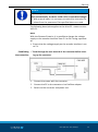
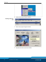
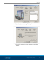


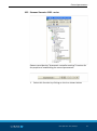
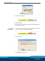
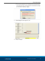
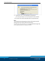


![[Download] azionamenti-hcs01](http://vs1.manualzilla.com/store/data/006141009_1-1242967de3765f3b826dc0b688197751-150x150.png)