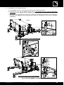
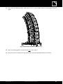
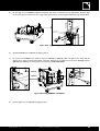
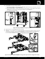
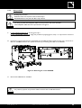
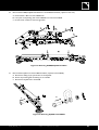
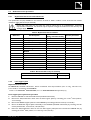
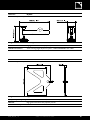
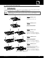
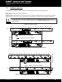
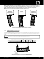
1
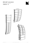
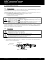
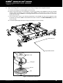
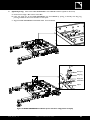
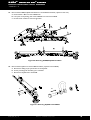
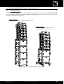
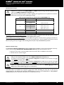
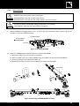
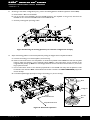
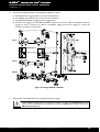
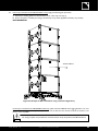
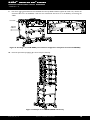
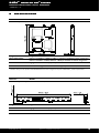
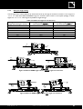
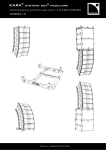
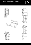
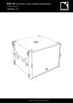
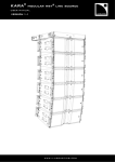
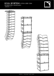
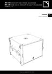
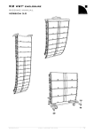
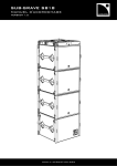
18. Remove the M-BUMP from SB18#1 as follows:
a.
b.
c.
d.
e.
Disconnect a bottom T-BLP from the M-BUMP.
Rotate the rigging arm down.
Re-connect the T-BLP to SB18#1 so as to lock the rigging arm in closed position.
Repeat this procedure until all 4 arms are locked in closed position.
Remove the M-BUMP from the array.
M-BUMP
(x4)
a.
SB18#1
b.
c.
SB18#2
Figure 42: M-BUMP removal
19. If necessary, set the M-BUMP for transport by removing each M-BAR as follows: remove both T-BLP from the
M-BAR studs, remove the M-BAR, and re-insert both T-BLP in their storage locations.
Figure 43: Single M-BAR storage example
20. Attach two dolly boards to SB18#1 and 2.
21. Detach SB18#2 from SB18#1 by applying step 10 and remove both subwoofers from the rigging location.
KARA_RM_EN_1-3
www.l-aco u sti cs.co m
33
KARA® MODULAR WST® SYSTEM
rigging procedures using mm-bump
VERSION 1.3
6.3
Stacking a KARA standalone array
6.3.1
Modeling and safety
A KARA array must be stacked onto an M-BUMP/M-BAR/M-JACK platform (platform stacked array). The platform
provides tilt adjustments in case of slope surface and increases the array stability.
Any platform stacked array must be modeled before installation so as to ensure acoustical conformity. This can be
done using L-ACOUSTICS® SOUNDVISION Software [3.4] which will assist the user to:
• Determine the number of required KARA enclosures.
• Calculate the inter-enclosure angles.
A platform stacked array can be composed of a maximum of 9 KARA enclosures along with all
loudspeakers cables (refer to the KARA User manual [3.4]).
WARNING
The platform must be installed in rear extension configuration if the KARA array is intended to have a
positive site angle (refer to [9.3.1]).
The platform must be installed in front extension configuration if the KARA array is intended to have a
negative site angle (refer to [9.3.1]) and a flat shape (all inter-enclosure angles are close to 0°).
The KARA and M-BUMP fully integrated rigging systems allow assembling the array with no need for any external
accessory. The following first procedure describes how to mount a vertical KARA platform stacked array. The
second procedure describes how to disassemble the array.
6.3.2
WARNING
Array mounting
All along the procedure:
STRICTLY follow the sequence of the successive steps.
SYSTEMATICALLY verify that each BLP is fully inserted.
SYSTEMATICALLY verify that each bolt is fully screwed in and secured with pin.
For clarity purposes the loudspeaker cabling procedure will not be described.
The loudspeaker cables will not be represented on the figures.
CAUTION
1.
Place an M-BUMP at the rigging location. Turn it so that the text of the identification plate is upside down and the
laser slits are directed towards the audience.
Identification plate
Towards audience
Laser slits
Figure 44: Installing M-BUMP
KARA_RM_EN_1-3
www.l-aco u sti cs.co m
34
2.
Mount two M-BAR/M-JACK assemblies as follows (repeat for each M-BAR):
a. Remove the safety pin [9.4] and the bolt from a shackle.
b. Place an M-JACK under one end of an M-BAR and align the M-JACK hole with the second M-BAR hole.
c. Secure by inserting the preceding bolt and safety pin.
d. Repeat the procedure to attach a second M-JACK to the other end of the M-BAR.
Second hole
b.
a.
c.
d.
Figure 45: Mounting an M-BAR/M-JACK assembly
3.
According to the chosen configuration [9.3.1], mount the stacking platform as follows (repeat for each M-BAR):
a. Remove both T-BLP from an M-BAR.
b. Lift up one side of the M-BUMP, place the M-BAR beneath it with M-JACK on the ground, and lower the
M-BUMP so as to insert both M-BAR studs into the M-BUMP slits.
c. Secure by inserting both preceding T-BLP.
c.
b.
Stud
Figure 46: Mounting the stacking platform (rear extension configuration example)
KARA_RM_EN_1-3
www.l-aco u sti cs.co m
35
KARA® MODULAR WST® SYSTEM
rigging procedures using mm-bump
VERSION 1.3
4.
Adjust the stacking platform in horizontal position by setting the heights of the 4 M-JACK as follows:
a. Unscrew the locking nut on each M-JACK (16 mm hex key).
b. Place an inclinometer device onto the platform in the direction parallel to the M-BAR and rotate the 4 M-JACK
knobs to adjust the platform in the horizontal position. Note 1: The inclinometer can be mounted to the
integrated laser plate [9.1]. Note 2: In case of high resistance the user can also screw the base nut (14 mm hex
key) in place of a knob.
c. Put an inclinometer device in the direction perpendicular to the M-BAR and verify that the platform is also
horizontal in this direction. Note: The handheld inclinometer included in the TECH TOOLCASE [3.4] can be
used in this step.
d. Lock each M-JACK height by firmly screwing in the locking nut (16 mm hex key).
Parallel direction
Perpendicular direction
Knob
Locking nut
Base nut
Base
Figure 47: Horizontal adjustment
KARA_RM_EN_1-3
www.l-aco u sti cs.co m
36
5.
(Optional [9.3.2]) Mount both KARA-ANGARMEX to the M-BUMP as follows (repeat for each one):
a. Remove the storage T-BLP and the rear R-BLP.
b. Insert the single part of the KARA-ANGARMEX into the M-BUMP by putting it vertically with sling ring
pointing towards the front and indentation on the spacer.
c. Align the KARA-ANGARMEX and M-BUMP holes. Insert the R-BLP.
a.
b.
Dual part
a.
c.
Sling ring
Single part
Indentation
Spacer
Figure 48: KARA-ANGARMEX installation (front extension configuration example)
KARA_RM_EN_1-3
www.l-aco u sti cs.co m
37
KARA® MODULAR WST® SYSTEM
rigging procedures using mm-bump
VERSION 1.3
6.
Remove both front R-BLP from the M-BUMP. If the M-BUMP has been configured without KARA-ANGARMEX,
also remove both rear R-BLP.
7.
Place a full KARA flight-case at the stacking location and remove the lid. In the following, the enclosures will be
designated as KARA#1 to KARA#3 from top to bottom.
8.
Set KARA#1 in stacking configuration as follows (repeat for each side):
a. Remove the front top R-BLP from its storage hole, rotate the front arm up, slide it down, and secure by reinserting the R-BLP into the top yellow link hole.
b. Remove the rear top R-BLP from its storage hole, slide the angle arm so as to align the cursor with the chosen
angle value, and secure by re-inserting the R-BLP into the corresponding angle hole (0°/2°/4° or
1°/3°/5°/7.5°/10°). Refer to [9.3.2] for equivalence between the chosen angle value and the array site angle.
c. Remove the front and rear bottom link R-BLP and re-insert them into the bottom storage holes.
a.
L
L
c.
KARA#1
b.
Cursor
L
L
c.
KARA#2
KARA#3
Figure 49: Setting KARA#1 in stacking configuration
KARA_RM_EN_1-3
www.l-aco u sti cs.co m
38
9.
Link KARA#1 to the M-BUMP as follows:
a. Lift up KARA#1 and turn it arms downwards and front face towards the audience.
b. Insert the four arms into the M-BUMP rigging points. If the M-BUMP has been configured with KARAANGARMEX, the rear rigging points become those of the KARA-ANGARMEX.
c. Secure both front rigging points by inserting the R-BLP into the M-BUMP. Depending on the configuration,
secure both rear rigging points by inserting either both R-BLP into the M-BUMP or both T-BLP into the KARAANGARMEX.
KARA#1
Rear extension configuration without KARA-ANGARMEX
b.
c.
Front extension configuration with KARA-ANGARMEX
Figure 50: Linking KARA#1 to M-BUMP
KARA_RM_EN_1-3
www.l-aco u sti cs.co m
39
KARA® MODULAR WST® SYSTEM
rigging procedures using mm-bump
VERSION 1.3
10. Set KARA#2 in rigging configuration by applying step 8.
11. Link KARA#2 to KARA#1 as follows:
a. Put KARA#2 upside down and direct the front grill towards the audience.
b. Insert the four arms into the KARA#1 rigging points.
c. Secure the four rigging points by removing the four KARA#1 top R-BLP from their storage holes and reinserting them into the top yellow link holes.
b.
c.
L
b.
c.
L
KARA#2
KARA#1
Figure 51: Linking KARA#2 to KARA#1
12. Link KARA#3 to KARA#2 by applying steps 10 and 11 (do not remove the 4 bottom R-BLP from KARA#3).
KARA_RM_EN_1-3
www.l-aco u sti cs.co m
40
13. Using other full KARA flight-cases, repeat steps 10 and 11 until all KARA enclosures composing the array are
rigged.
Figure 52: Example of KARA standalone array
14. Check if the stacking platform is still horizontal. If not, refer to step 4.
15. Secure the system to a fixed point using a ratchet strap or any other applicable material (not included).
KARA_RM_EN_1-3
www.l-aco u sti cs.co m
41
KARA® MODULAR WST® SYSTEM
rigging procedures using mm-bump
VERSION 1.3
6.3.3
WARNING
Array removal
All along the procedure:
STRICTLY follow the sequence of the successive steps.
SYSTEMATICALLY verify that each BLP is fully inserted.
For clarity purposes the loudspeaker cables removal procedure will not be described.
The loudspeaker cables will not be represented on the figures.
CAUTION
1.
Remove the ratchet strap from the array.
2.
Place an empty KARA flight-case at the rigging location and remove the lid.
3.
Separate the top KARA (KARA#3 for example) from the KARA below (KARA#2 for example) as follows: remove
the 4 top link R-BLP from KARA#2 and re-insert them into the top storage holes.
KARA#3
KARA#2
KARA#1
Figure 53: Separating KARA#3 from KARA#2
4.
Lift up and turn KARA#3 arms upwards. Put KARA#3 into the flight-case tray.
Pay attention to the flight-case position: both wedges must slope upwards from front to rear.
WARNING
KARA#3
Wedge
Figure 54: Putting KARA#3 into the flight-case tray
KARA_RM_EN_1-3
www.l-aco u sti cs.co m
42
5.
Set the angle to 0° on KARA#3 as follows (repeat for each side): remove the rear top angle R-BLP, slide the angle
arm so as to align the cursor with the 0° angle value, and secure by re-inserting the R-BLP into angle hole 0°/2°/4°.
0°
Figure 55: 0° angle setting
6.
Separate KARA#2 from KARA#1 by applying step 3.
7.
Lift up and turn KARA#2 arms upwards. Connect KARA#2 to KARA#3 (with two grills on the same side) by
aligning the 4 rigging points between both enclosures. Remove the 4 R-BLP from the bottom storage holes of
KARA#2 and secure by re-inserting them into the bottom yellow link holes.
KARA#2
KARA#3
Figure 56: Linking KARA#2 to KARA#3
8.
Set the angles to 0° on KARA#2 by applying step 5.
KARA_RM_EN_1-3
www.l-aco u sti cs.co m
43
KARA® MODULAR WST® SYSTEM
rigging procedures using mm-bump
VERSION 1.3
9.
Separate KARA#1 from the M-BUMP as follows (or repeat the procedure from step 3 if the top enclosure is not
KARA#1):
a. Remove both front R-BLP from the M-BUMP.
b. Depending on the configuration, remove either both rear R-BLP from the M-BUMP or both T-BLP from the
KARA-ANGARMEX.
KARA#1
b.
Rear extension configuration without KARA-ANGARMEX
a.
b.
Front extension configuration with KARA-ANGARMEX
Figure 57: Separating KARA#1 from M-BUMP
10. Attach KARA#1 to KARA#2 by applying step 7.
KARA_RM_EN_1-3
www.l-aco u sti cs.co m
44
11. Set the KARA#1-3 array for transport as follows:
a. On both sides of KARA#1, remove the front top link R-BLP, slide the front arm up, rotate down, and secure
by re-inserting the R-BLP on the top storage hole.
b. On both sides of KARA#1, remove the rear top R-BLP, slide the angle arm so as to align the cursor with the
storage position, and secure by re-inserting the top R-BLP on the top storage hole.
c. Put the flight-case lid back in place.
a.
b.
L
L
Figure 58: Setting the KARA#1-3 array for transport
12. Repeat steps 2 to 11 until all KARA enclosures are removed.
13. (Optional) On the M-BUMP, put both KARA-ANGARMEX in storage position as follows (repeat for each one):
a. Remove the rear R-BLP, remove the KARA-ANGARMEX, and re-insert the R-BLP into the M-BUMP hole.
b. Put the KARA-ANGARMEX horizontally in its storage location and secure by inserting the T-BLP.
a.
b.
Figure 59: Putting the KARA-ANGARMEX in storage position (front extension configuration example)
KARA_RM_EN_1-3
www.l-aco u sti cs.co m
45
KARA® MODULAR WST® SYSTEM
rigging procedures using mm-bump
VERSION 1.3
14. Remove both M-BAR/M-JACK assemblies from the M-BUMP as follows (repeat for each one):
a. Remove both T-BLP from the M-BAR studs.
b. Lift up the corresponding side of the M-BUMP and remove the M-BAR.
c. Re-insert both T-BLP into their storage holes.
Figure 60: Removing M-BAR/M-JACK assemblies
15. Remove both M-JACK from each M-BAR as follows (repeat for each M-BAR):
a. Remove the safety pin [9.4] and bolt from the M-JACK.
b. Fix the preceding bolt and safety pin to a shackle.
c. Remove the M-JACK from the M-BAR.
a.
b.
Figure 61: Removing M-JACK from M-BAR
KARA_RM_EN_1-3
www.l-aco u sti cs.co m
46
6.4
Stacking a SB18/KARA mixed array or a SB18 standalone array
6.4.1
Modeling and safety
A SB18/KARA mixed array or a SB18 standalone array can be stacked directly on the ground (ground stacked array)
or onto an M-BUMP/M-BAR/M-JACK platform (platform stacked array). Figure 62 shows a mixed array of each type
and gives the associated conditions of use.
Ground stacked array
•
To be stacked on a perfectly horizontal and regular surface ONLY
Platform stacked array
•
•
Provides tilt adjustments in case of slope surface
Increases KARA array site angle range
Figure 62: Examples of SB18/KARA stacked arrays
KARA_RM_EN_1-3
www.l-aco u sti cs.co m
47
KARA® MODULAR WST® SYSTEM
rigging procedures using mm-bump
VERSION 1.3
Ground stacked arrays
A ground stacked array requires to be installed on a perfectly horizontal and regular surface. It can be
composed of a maximum of 4 SB18/9 KARA or 8 SB18 enclosures along with all loudspeakers cables
(refer to the KARA and SB18 User manuals [3.4]).
WARNING
Apply the setup safety limits given in Table 2 regarding the angle between the top SB18 and the bottom
KARA (refer to [9.3.2] for bottom KARA angle settings):
Table 2: Setup safety limits for ground stacked SB18/KARA array
Number of SB18
Number of KARA
1-3
4-5
6-9
1-6
7
8
9
1-8
9
1-9
1
2
3
4
Bottom KARA authorized angle range
From -15° to +5°
From -7.5° to +5°
From -5° to +5°
From -15° to +5°
From -12° to +5°
From -10° to +5°
From -7.5° to +5°
From -15° to +5°
From -12° to +5°
From -15° to +5°
SB18/KARA mixed array mounting procedure: Put the bottom SB18 on the ground (front grill logo upside) and apply
the [6.4.2] procedure WITHOUT using the M-BUMP/M-BAR/M-JACK platform.
SB18 standalone array mounting procedure: Put a first SB18 on the ground with feet (and front grill logo) downside. Put
a second SB18 onto the first one and link both enclosures by applying [6.2.2, step 4c]. Repeat the procedure until all
SB18 composing the array are rigged. While installing follow the [6.2.2, step 8, IMPORTANT] indication.
Platform stacked arrays
Any SB18/KARA platform stacked array must be modeled before installation so as to ensure acoustical conformity.
This can be done using L-ACOUSTICS® SOUNDVISION Software [3.4] which will assist the user to:
• Determine the number of required KARA enclosures (acoustic data not available for subwoofers).
• Calculate the inter-enclosure angles.
A platform stacked array can be composed of a maximum of 2 SB18/6 KARA or 4 SB18 enclosures
along with all loudspeakers cables (refer to the KARA and SB18 User manuals [3.4]).
WARNING
The platform must be installed in rear extension configuration if a KARA array is intended to be rigged
with a positive site angle (refer to [9.3.1]).
The platform must be installed in front extension configuration if a KARA array is intended to be rigged
with a negative site angle (refer to [9.3.1]) and a straight shape (all inter-enclosure angles are close to 0°).
NEVER use M-BUMP and KARA-MINIBU within the same array (refer to the KARA Rigging procedures
pack [3.4] for KARA-MINIBU rigging structure description).
WARNING
The KARA, SB18, and M-BUMP fully integrated rigging systems allow assembling the array with no need for any
external accessory. The following first procedure describes how to mount a vertical SB18/KARA or SB18 platform
stacked array. The second procedure describes how to disassemble the array.
KARA_RM_EN_1-3
www.l-aco u sti cs.co m
48
6.4.2
WARNING
Array mounting
All along the procedure:
STRICTLY follow the sequence of the successive steps.
SYSTEMATICALLY verify that each BLP is fully inserted.
SYSTEMATICALLY verify that each bolt is fully screwed in and secured with pin.
For clarity purposes the loudspeaker cabling procedure will not be described.
The loudspeaker cables will not be represented on the figures.
CAUTION
1.
Place an M-BUMP at the rigging location. Turn it so that the text of the identification plate is upside down and the
laser slits are directed towards the audience.
Identification plate
Towards audience
Laser slits
Figure 63: Installing M-BUMP
2.
Mount two M-BAR/M-JACK assemblies as follows (repeat for each M-BAR):
a.
b.
c.
d.
Remove the safety pin [9.4] and the bolt from a shackle.
Place an M-JACK under one end of an M-BAR and align the M-JACK hole with the second M-BAR hole.
Secure by inserting the preceding bolt and safety pin.
Repeat the procedure to attach a second M-JACK to the other end of the M-BAR.
Second hole
b.
a.
c.
d.
Figure 64: Mounting an M-BAR/M-JACK assembly
KARA_RM_EN_1-3
www.l-aco u sti cs.co m
49
KARA® MODULAR WST® SYSTEM
rigging procedures using mm-bump
VERSION 1.3
3.
According to the chosen configuration [9.3.1], mount the stacking platform as follows (repeat for each M-BAR):
a. Remove both T-BLP from an M-BAR.
b. Lift up one side of the M-BUMP, place the M-BAR beneath it with M-JACK on the ground, and lower the
M-BUMP so as to insert both M-BAR studs into the M-BUMP slits.
c. Secure by inserting both preceding T-BLP.
c.
b.
Stud
Figure 65: Mounting the stacking platform (rear extension configuration example)
4.
Adjust the stacking platform in horizontal position by setting the heights of the 4 M-JACK as follows:
a. Unscrew the locking nut on each M-JACK (16 mm hex key).
b. Place an inclinometer device onto the platform in the direction parallel to the M-BAR and rotate the 4 M-JACK
knobs to adjust the platform in the horizontal position. Note 1: The inclinometer can be mounted to the
integrated laser plate [9.1]. Note 2: In case of high resistance the user can also screw the base nut (14 mm hex
key) in place of a knob.
c. Put an inclinometer device in the direction perpendicular to the M-BAR and verify that the platform is also
horizontal in this direction. Note: The handheld inclinometer included in the TECH TOOLCASE [3.4] can be
used in this step.
d. Lock each M-JACK height by firmly screwing in the locking nut (16 mm hex key).
Knob
Locking nut
Base nut
Parallel direction
Base
Perpendicular direction
Figure 66: Horizontal adjustment
KARA_RM_EN_1-3
www.l-aco u sti cs.co m
50
5.
Link a first SB18 (hereafter called SB18#1) to the M-BUMP as follows:
a. Place SB18#1 at the rigging location and remove the dolly board.
b. Turn the SB18#1 logo upwards. Orient the front grill towards the audience or backwards.
IMPORTANT
Orient all SB18 composing the array towards the audience to obtain an omnidirectional
acoustic pattern. Orient one SB18 every four backwards to obtain a cardioid acoustic pattern
(refer to the SB18 User manual [3.4]).
c. Place SB18#1 on the M-BUMP by aligning the four rigging points.
d. Link the four rigging arms of SB18#1 to the M-BUMP as follows: disconnect a T-BLP from SB18#1, rotate the
rigging arm down, re-connect the T-BLP to the M-BUMP rigging point and the rigging arm ; repeat this
procedure until all 4 arms are secured.
d.
SB18#1
M-BUMP
Figure 67: Linking SB18#1 to M-BUMP
KARA_RM_EN_1-3
www.l-aco u sti cs.co m
51
KARA® MODULAR WST® SYSTEM
rigging procedures using mm-bump
VERSION 1.3
6.
Attach a second SB18 (hereafter called SB18#2) to SB18#1 as follows:
a. Place SB18#2 at the rigging location and remove the dolly board.
b. Turn SB18#2 logo upwards and front face towards the audience.
c. Place SB18#2 on SB18#1 by aligning the four rigging points.
d. Attach the four rigging arms of SB18#2 to SB18#1 as follows: disconnect a T-BLP from SB18#2, rotate the
rigging arm down, re-connect the T-BLP to the SB18#1 rigging point and the rigging arm; repeat this
procedure until all 4 arms are secured.
d.
SB18#2
SB18#1
M-BUMP
Figure 68: Linking SB18#2 to SB18#1
7.
Repeat step 6 until all SB18 enclosures composing the array are rigged.
IMPORTANT
KARA_RM_EN_1-3
Orient all SB18 composing the array towards the audience to obtain an omnidirectional acoustic
pattern. Orient one SB18 every four backwards to obtain a cardioid acoustic pattern (refer to the
SB18 User manual [3.4]).
www.l-aco u sti cs.co m
52
8.
If the array is intended to be a SB18 standalone array, apply the following last procedure:
a. Check if the stacking platform is still horizontal. If not, refer to [6.3.2, step 4].
b. Secure the system to a fixed point using a ratchet strap or any other applicable material (not provided).
PROCEDURE END
Towards audience
Figure 69: Example of SB18 standalone array (cardioid configuration)
If the array is intended to be a SB18/KARA mixed array, place a second M-BUMP at the rigging location. Turn it so
that the text of the identification plate is upside down and the laser slits are directed towards the audience, and
place it on the top SB18.
For clarity purposes, the procedure is continued with an array composed of one SB18 enclosure.
IMPORTANT
KARA_RM_EN_1-3
www.l-aco u sti cs.co m
53
KARA® MODULAR WST® SYSTEM
rigging procedures using mm-bump
VERSION 1.3
9.
Link the 4 rigging points between the M-BUMP and the top SB18 as follows (repeat for each one): remove the
external T-BLP from the M-BUMP, rotate the arm downwards and secure it to the SB18 by re-inserting the
T-BLP.
Laser slits
Towards
audience
Figure 70: Installing a second M-BUMP (rear extension configuration example for the bottom M-BUMP)
10. Finish the procedure by applying [6.3.2 from step 5 to the end].
Figure 71: Example of stacked SB18/KARA mixed array
KARA_RM_EN_1-3
www.l-aco u sti cs.co m
54
6.4.3
WARNING
Array removal
All along the procedure:
STRICTLY follow the sequence of the successive steps.
SYSTEMATICALLY verify that each BLP is fully inserted.
For clarity purposes the loudspeaker cables removal procedure will not be described.
The loudspeaker cables will not be represented on the figures.
CAUTION
1.
In case of SB18 standalone array, directly go to step 4.
In case of SB18/KARA mixed array, begin the procedure by applying [6.3.3, steps 1 to 13] and then continue to
next step.
2.
Unlink the 4 rigging points between the M-BUMP and the SB18 as follows (repeat for each one): remove the TBLP from the SB18, rotate the arm upwards and lock it by re-inserting the T-BLP on the M-BUMP.
Figure 72: Removing the second M-BUMP
3.
Remove the M-BUMP from the SB18.
!
For precision purposes, the procedure will be continued with two SB18 enclosures.
IMPORTANT
KARA_RM_EN_1-3
www.l-aco u sti cs.co m
55
KARA® MODULAR WST® SYSTEM
rigging procedures using mm-bump
VERSION 1.3
4.
If not already done, remove the ratchet strap from the array.
5.
Unlink the top SB18 (SB18#2 for example) from the SB18 below (SB18#1 for example) as follows:
a. Disconnect a T-BLP from the top part of SB18#1.
b. Rotate the rigging arm up.
c. Re-connect the T-BLP to SB18#2 so as to lock the rigging arm in closed position.
d. Repeat this procedure until all 4 arms are locked in closed position.
SB18#2
c.
b.
a.
SB18#1
M-BUMP
Figure 73: Detaching SB18#2 from SB18#1
6.
Attach a dolly board to SB18#2 and remove SB18#2 from the rigging location.
7.
Repeat steps 5 and 6 until all SB18 are separated from the array.
KARA_RM_EN_1-3
www.l-aco u sti cs.co m
56
8.
Remove both M-BAR/M-JACK assemblies from the M-BUMP as follows (repeat for each one):
a. Remove both T-BLP from the M-BAR studs.
b. Lift up the corresponding side of the M-BUMP and remove the M-BAR.
c. Re-insert both T-BLP into their storage holes.
Figure 74: Removing M-BAR/M-JACK assemblies
9.
Remove both M-JACK from each M-BAR as follows (repeat for each M-BAR):
a. Remove the safety pin [9.4] and bolt from the M-JACK.
b. Secure the preceding bolt and safety pin to a shackle.
c. Remove the M-JACK from the M-BAR.
a.
b.
Figure 75: Removing M-JACK from M-BAR
KARA_RM_EN_1-3
www.l-aco u sti cs.co m
57
KARA® MODULAR WST® SYSTEM
rigging procedures using mm-bump
VERSION 1.3
7
CARE AND MAINTENANCE
MAINTENANCE
7.1
Maintenance information
The KARA® system assembling components are the following:
•
M-BUMP rigging structure with rotating arms.
•
M-BAR extension bar.
•
M-JACK feet.
•
KARA-ANGARMEX angle arm extensions.
•
KARA-PULLBACK rigging accessory.
•
KARA® enclosures with rotating arms and angle arms.
•
SB18 enclosures with rigging arms.
•
Shackles with bolts and safety pins.
•
Ball locking pins (R-BLP and T-BLP).
If these components are used as it is described in this manual they will remain fully operational over the enclosures’ life.
However, it is necessary to regularly check the following points in order to guarantee the system durability:
!
WARNING
!
WARNING
!
WARNING
The M-BUMP, M-BAR, M-JACK, KARA-ANGARMEX, and KARA-PULLBACK elements (including shackles
and BLP) should not show any deformation, fissure, or oxidation.
Any component incorporating a part showing signs of defect must immediately be replaced [7.2].
The metal components of the KARA® and SB18 enclosures should not show any signs of deformation,
fissure, or oxidation. They must be securely fixed to the enclosures.
Any enclosure incorporating a part showing signs of defect must immediately be put aside and withdrawn
from use to be inspected by qualified service personnel.
Verify that each BLP operates normally by moving its mechanism and checking that it automatically returns
to nominal position.
Verify the screwing mechanism on each shackle. Verify that the safety pin is present and that it locks
correctly [9.4].
KARA_RM_EN_1-3
www.l-aco u sti cs.co m
58
7.2
Authorized service procedures
7.2.1
Replacement kits and recommended tools
The replacement kits (KR) available for the customer are listed in Table 3. Table 4 is a list of all tools and material
needed for rigging and service (not included).
WARNING
Service and repair work for any other part must be carried out by an L-ACOUSTICS® authorized
representative. Otherwise, the customer may be exposed to dangerous situations and the warranty will
no longer apply.
Table 3: Replacement kits and utilities
Reference
KR MBUMPLAS
KR MAN19L
KR PIN621
KR PIN601
KR LOCKBLUE
KR MAN19L
KR PIN665
KR PIN601
KR PIN601
KR MAN19L
Kit description
M-BUMP
Laser support plate
19 mm shackle with safety pin
5/16” R-BLP
5/16” T-BLP
Medium-strength thread-locker
M-BAR
19 mm shackle with safety pin
3/8” T-BLP
M-JACK
5/16” T-BLP
KARA-ANGARMEX
5/16” T-BLP
KARA-PULLBACK
19 mm shackle with safety pin
Kit contents
(fixing material included)
Service procedure
1 plate
4 shackles
10 pins
10 pins
5 pipettes of 50 g
[7.2.2]
—
—
—
—
4 shackles
10 pins
—
—
10 pins
—
10 pins
—
4 shackles
—
Table 4: Recommended tools (not included)
Electric screwdriver with torque selector (N.m or in.lbf)
T20 Torx® bit
7.2.2
5 mm hex bit
7 mm hex key
Laser support plate
Replacement kit and tools
KR MBUMPLAS, handheld inclinometer1, electric screwdriver with torque selector (N.m or in.lbf), T20 Torx® bit,
5 mm hex bit, 7 mm hex key, KR LOCKBLUE.
1
Available in the L-ACOUSTICS ® TECH TOOLCASE (refer to the TECH TOOLCASE Product spec sheet [3.4]).
Laser support plate replacement procedure
1.
Place the M-BUMP on a flat horizontal surface (handheld inclinometer).
2.
Remove the laser/inclinometer device from the laser support plate by unscrewing the 4 Torx® bolts (T20 bit,
7 mm hex key).
3.
Remove the old laser support plate from the M-BUMP by unscrewing both hex screws (5 mm hex bit).
4.
Secure the new laser support plate horizontally to the M-BUMP (handheld inclinometer) by screwing two hex
screws (thread-locker, 5 mm hex bit, 5 N.m/45 in.lbf).
5.
Mount the laser/inclinometer device on the new laser support plate (laser lens towards the M-BUMP slits) by
screwing the 4 Torx® bolts (T20 bit, 7 mm hex key, 3 N.m/27 in.lbf).
KARA_RM_EN_1-3
www.l-aco u sti cs.co m
59
KARA® MODULAR WST® SYSTEM
rigging procedures using mm-bump
VERSION 1.3
8
SPECIFICATIONS
Reference
M-BUMP
Dimensions (L x H x D)
750 x 80 x 700 mm / 29.5 x 3.1 x 27.6 inch
Weight
25 kg / 55 lbs
Setup safety limits
1
Maximum 24 KARA or 4 SB18/12 KARA or 16 SB18 per M-BUMP in flown configuration.
Maximum 9 KARA or 2 SB18/6 KARA or 4 SB18 per M-BUMP in stacked configuration.
Material
High-grade steel coated with polyester powder.
Included accessories
4 R-BLP, 4 rotating arms with T-BLP, 1 laser support plate with 4 bolts, 2 shackles.
1
Installation safety limits are specified in SOUNDVISION Software which is designed to help with L-ACOUSTICS® product implementation.
Reference
M-BAR
Dimensions (L x H x D)
954 x 111.7 x 60 mm / 37.6 x 4.4 x 2.4 inch
Weight
5 kg / 11 lbs
Material
High-grade steel coated with polyester powder.
Included accessories
2 T-BLP, 2 shackles.
KARA_RM_EN_1-3
www.l-aco u sti cs.co m
60
Reference
M-JACK
Dimensions (L x H x D)
265 x 144 x 80 mm / 10.4 x 5.7 x 3.1 inch
Weight
4 x 1.15 kg / 2.5 lbs
Material
High-grade steel coated with polyester powder.
Included accessories
4 foot including height-adjustment system, 2 KARA-ANGARMEX with T-BLP.
Reference
KARA-PULLBACK
Dimensions (L x H x D)
668 x 40 x 511.2 mm / 26.3 x 1.6 x 20.1 inch
Weight
6 kg / 13 lbs
Setup safety limits [9.2.3] Maximum of 12 KARA or 3 SB18/9 KARA enclosures per KARA-PULLBACK.
Material
High-grade steel coated with polyester powder.
Included accessory
1 shackle.
KARA_RM_EN_1-3
www.l-aco u sti cs.co m
61
KARA® MODULAR WST® SYSTEM
rigging procedures using mm-bump
VERSION 1.3
9
APPENDIX
9.1
LAP-TEQ inclinometer mounting
A laser support plate has been integrated inside the M-BUMP for optional TEQSAS® LAP-TEQ inclinometer/laser
device mounting. The LAP-TEQ is a remote control device part of the L-ACOUSTICS® TECH TOOLCASE (refer to
the TECH TOOLCASE Product spec sheet [3.4]).
Laser support plate
with 4 Torx® bolts
Inclinometer mounted
to the laser support
plate
Figure 76: Laser support plate and LAP-TEQ inclinometer mounted to it
LAP-TEQ mounting procedure
Required tools
Handheld inclinometer (available in the TECH TOOLCASE), electric screwdriver with torque selector (N.m or in.lbf),
T20 Torx® bit, 7 mm hex key, XLR3 cable.
Procedure
1. Place the M-BUMP on a flat horizontal surface (handheld inclinometer).
2. Unscrew the four Torx® bolts from the laser support plate (T20 bit, 7 mm hex key).
3. Mount the LAP-TEQ sensor on the laser support plate with laser lens towards the M-BUMP slits.
4. Screw the 4 Torx® bolts to the sensor and plate (T20 bit, 7 mm hex key, 3 N.m/27 in.lbf).
5. Connect an XLR 3 cable to the sensor.
6. Calibrate the sensor by following the manufacturer’s recommendations.
KARA_RM_EN_1-3
www.l-aco u sti cs.co m
62
9.2
Flown array options and site angle setting
9.2.1
M-BUMP rigging options
L-ACOUSTICS® recommends 5 different rigging options to fly the M-BUMP for arrays containing KARA and/or SB18
enclosures. It is possible to use 0, 1, or 2 M-BAR and 1 or 2 rigging points (see Figure 77).
ALWAYS refer to the mechanical data and warning indications provided in SOUNDVISION software
(Mechanical Data section) to verify the mechanical conformity of the system before installation.
WARNING
Rear
Front
Option 1: 0 M-BAR, 1 point
1 motor
3 positions (front, center, rear)
Option 2: 0 M-BAR, 2 points
2 motors
Fixed front and rear positions
(spacing = 400 mm/15 inch)
Option 3: 1 M-BAR, 1 point
1 motor
Variable position [9.2.2]
Left view = rear extension configuration
Right view = front extension configuration
Option 4: 1 M-BAR, 2 points
2 motors
Fixed front and rear positions
(spacing = 900 mm/35 inch)
Left view = rear extension configuration
Right view = front extension configuration
Option 5: 2 M-BAR, 2 points
2 motors
Variable position from front to rear
Same hole number for both points [9.2.2]
(spacing = 663 mm/26 inch)
Left view = rear extension configuration
Right view = front extension configuration
Figure 77: M-BUMP rigging options
KARA_RM_EN_1-3
www.l-aco u sti cs.co m
63
KARA® MODULAR WST® SYSTEM
rigging procedures using mm-bump
VERSION 1.3
9.2.2
M-BUMP site angle setting
The M-BUMP site angle setting will be discrete or continuous depending on the chosen rigging option.
Rigging option 1 offers three discrete angle values.
Rigging options 3 and 5 offer 34 discrete angle values. First select the M-BAR position (A or B) and then the shackle
position (holes 0-16) as shown in Figure 78 (rear extension configuration) or Figure 79 (front extension configuration).
For rigging options 1, 3, and 5 the M-BUMP site angle will also depend on the size and shape of the array
(number of enclosures and inter-enclosure angles). Refer to SOUNDVISION Software [3.4] for site
angle calculation.
IMPORTANT
M-BAR hole numbering convention
0
2
1
3
4
5
6
7
8
9
10
11
12
13
14
15
16
Rear
Front
M-BAR flush with M-BUMP
M-BAR in position A on the M-BUMP
M-BAR in position B on the M-BUMP
16
15
14
13
12
11
10
9
8
7
6
5
4
3
2
M-BAR in position A on the M-BUMP
1
0
M-BAR flush with M-BUMP
Figure 78: Discrete angle selection (rear extension configuration)
M-BAR in position B on the M-BUMP
Rear
Front
Figure 79: Discrete angle selection (front extension configuration)
KARA_RM_EN_1-3
www.l-aco u sti cs.co m
64
Rigging options 2 and 4 allow continuous M-BUMP site angle setting depending on the relative heights between the
front and rear rigging points. Option 2 offers a small setting range. Option 4 enlarges the setting range for negative site
angles in rear extension configuration and positive site angles in front extension configuration (see Figure 80).
Note: For option 4, it is recommended to position both shackles in holes 0 and 16.
Rear extension
configuration for
negative site angles
Front extension
configuration for
positive site angles
Horizontal
0° site angle
Figure 80: Continuous angle selection (option 4 example)
9.2.3
KARA-PULLBACK setup safety limits
The KARA-PULLBACK accessory mounts to the bottom enclosure of a KARA array to allow setting the site angle down
to -90° and obtain a pullback configuration. However, this limit depends on the composition of the array as shown in
Table 5.
ALWAYS refer to Table 5 before using the KARA-PULLBACK accessory.
WARNING
Table 5: Possible downwards site angles with KARA-PULLBACK
Number of KARA enclosures in the array
Number of SB18 enclosures in the array
Maximum array downwards site angle
12
0
-90°
9
3
-60°
6
2
-90°
3
1
-90°
-90°
Figure 81: 90° downwards site angle with KARA-PULLBACK
KARA_RM_EN_1-3
www.l-aco u sti cs.co m
65
KARA® MODULAR WST® SYSTEM
rigging procedures using mm-bump
VERSION 1.3
9.3
Stacked array options and site angle setting
9.3.1
Stacking platform configuration
The M-BUMP can be used as a horizontal stacking platform along with two M-BAR and four M-JACK bases in front or
rear extension configuration as shown in Figure 82 and Figure 83 (refer to [9.3.2] for bottom KARA angle settings).
The configurations shown in Figure 82 and Figure 83 are purely indicative.
Refer to [6.3.1] and [6.4.1] for setup safety limits.
WARNING
Positive site angle
Horizontal line
Positive site angle
Horizontal line
Rear extension
Rear extension
Figure 82: Rear extension configurations
Horizontal line
Negative site angle
Horizontal line
Negative site angle
Front extension
Front extension
Figure 83: Front extension configurations
KARA_RM_EN_1-3
www.l-aco u sti cs.co m
66
9.3.2
Array site angle setting
The site angle of the stacked KARA array will be determined by the angle of the bottom enclosure in the range from
-15° to +5°. Install both KARA-ANGARMEX angle arm extensions (also included in the M-JACK package) to obtain
angles from -7.5° to -15°. Table 6 gives all possible site angles settings:
Table 6: Possible site angles for stacked array
Angle selection on KARA
(angle value facing the cursor)
0°
1°
2°
3°
4°
5°
7.5°
10°
Resulting site angle without angle
arm extension (Figure 84)
-5°
-4°
-3°
-2°
-1°
0°
+2.5°
+5°
Resulting site angle with angle
arm extension (Figure 85)
-15°
-14°
-13°
-12°
-11°
-10°
-7.5°
—
0°
5°
+5°
10°
0°
-5°
Figure 84: Bottom KARA angle selection without angle arm extensions
Figure 85: Bottom KARA angle selection with angle arm extensions
KARA_RM_EN_1-3
www.l-aco u sti cs.co m
67
KARA® MODULAR WST® SYSTEM
rigging procedures using mm-bump
VERSION 1.3
9.4
Safety pin removal and insertion
The safety pins part of the shackles have an integrated locking system. Figure 86 presents the removal and insertion
procedures.
ALWAYS put the safety pin in locked position before use.
WARNING
Unlock
Remove / Insert
Lock
Figure 86: Safety pin removal and insertion procedures
KARA_RM_EN_1-3
www.l-aco u sti cs.co m
68
www.l-aco u sti cs.co m
Document reference: KARA_RM_EN_1-3
Distribution date: April 5th, 2011
Printed on recycled paper
© 2011 L-ACOUSTICS®. All rights reserved.
No part of this publication may be reproduced or transmitted in any form
or by any means without the express written consent of the publisher.
www.l-aco u sti cs.co m


![[incr tsdb()]](http://vs1.manualzilla.com/store/data/005780303_1-7064634619abc733efac654e2a82e90d-150x150.png)