1
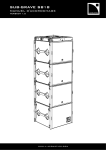
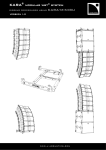
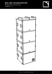
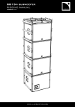
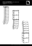
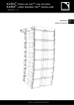
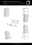
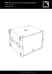
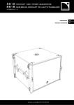
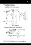
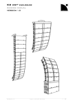
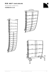
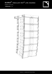
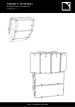
SB18 SUBWOOFER
RIGGING MANUAL
VERSION 1.0
www.l-acoustics.com
SB18 SUBWOOFER
rigging manual
VERSION 1.0
SAFETY INSTRUCTIONS
1.
Read this manual
2.
Heed all SAFETY INSTRUCTIONS as well as DANGER and OBLIGATION warnings
3.
Never incorporate equipment or accessories not approved by L-ACOUSTICS®
4.
Read all the related PRODUCT INFORMATION documents before exploiting the system
The product information document is included in the shipping carton of the related system component.
5.
Work with qualified personnel for rigging the system
Installation should only be carried out by qualified personnel that are familiar with the rigging techniques and safety
recommendations outlined in this manual.
6.
Ensure personnel health and safety
During installation and set-up personnel must wear protective headgear and footwear at all times. Under no
circumstances personnel is allowed to climb on a loudspeaker assembly.
7.
Respect the Working Load Limit (WLL) of third party equipment
L-ACOUSTICS® is not responsible for any rigging equipment and accessories provided by third party
manufacturers. Verify that the Working Load Limit (WLL) of the suspension points, chain hoists and all additional
hardware rigging accessories is respected.
8.
Respect the maximum configurations and the recommended safety level
For safety issue, respect the maximum configurations outlined in this manual. To check the conformity of any
configuration in regards with the safety level recommended by L-ACOUSTICS®, model the system in
SOUNDVISION and refer to the warnings in Mechanical Data section.
9.
Be cautious when flying a loudspeaker array
Always verify that no one is standing underneath the loudspeaker array when it is being raised. As the array is
being raised, check each individual element to make sure that it is securely fastened to the adjacent element.
Never leave the array unattended during the installation process. As a general rule, L-ACOUSTICS® recommends
the use of safety slings at all times.
10. Be cautious when ground-stacking a loudspeaker array
Do not stack the loudspeaker array on unstable ground or surface. If the array is stacked on a structure, platform,
or stage, always check that the latter can support the total weight of the array. As a general rule, L-ACOUSTICS®
recommends the use of safety straps at all times.
11. Take into account the wind effects on dynamic load
When a loudspeaker assembly is deployed in an open air environment, wind can produce dynamic stress to the
rigging components and suspension points. If the wind force exceeds 6 bft (Beaufort scale), lower down and/or
secure the loudspeaker array.
SB18_RM_EN_1-0
www.l-acoustics.com
2
SYMBOLS
The following symbols are used in this document:
DANGER
This symbol indicates a potential risk of harm to an individual or damage to the product. It can also notify the
user about instructions that must be strictly followed to ensure safe installation or operation of the product.
OBLIGATION
This symbol notifies the user about instructions that must be strictly followed to ensure proper installation or
operation of the product.
INFORMATION
This symbol notifies the user about complementary information or optional instructions.
WELCOME TO L-ACOUSTICS®
Thank you for choosing the L-ACOUSTICS® SB18 subwoofer enclosure.
This document contains essential information on rigging the system properly and safely. Carefully read this document in
order to become familiar with these procedures.
As part of a continuous evolution of techniques and standards, L-ACOUSTICS® reserves the right to
change the specifications of its products and the content of its document without prior notice.
Please check the L-ACOUSTICS® web site on a regular basis to download latest updates for documents and software:
www.l-acoustics.com.
CONTENTS
1
RIGGING SYSTEM
4
2
2.1
2.2
MECHANICAL SAFETY
6
Maximum configurations ............................................................................................................................................................. 6
Assessing mechanical safety ......................................................................................................................................................... 6
3
3.1
3.2
SYSTEM SET-UP
7
Ground-stacking .......................................................................................................................................................................... 7
Flying ........................................................................................................................................................................................... 8
4
A.
B.
C.
D.
RIGGING PROCEDURES
9
Attaching an SB18 to a second element ...................................................................................................................................... 9
Preparing the M-BUMP stacking platform ................................................................................................................................ 10
Preparing the M-BUMP flying structure .................................................................................................................................... 12
Preparing the KARA-MINIBU flying structure ........................................................................................................................... 13
APPENDIX A: M-BUMP FLYING OPTIONS
14
APPENDIX B: KARA-MINIBU FLYING OPTIONS
16
APPENDIX C: INSTALLING THE LAP-TEQ INCLINOMETER
17
APPENDIX D: SAFETY PIN MECHANISM ON SHACKLES
17
SB18_RM_EN_1-0
www.l-acoustics.com
3
SB18 SUBWOOFER
rigging manual
VERSION 1.0
1
RIGGING
RIGGING SYSTEM
The system approach developed by L-ACOUSTICS® consists in providing packaged solutions for loudspeaker system in
order to guarantee the highest and most predictable level of performance at any step: modeling, installation, and
operation. An L-ACOUSTICS® loudspeaker system is the set of components available to form any loudspeaker system
based on one of the full-range loudspeaker enclosure afforded by L-ACOUSTICS®. It includes enclosures, rigging
accessories, loudspeaker cables, amplified controllers, and software applications.
The SB18 subwoofer is especially adapted to the following systems: KUDO®, KARA®, KIVA/KILO, and to the coaxial XT
enclosures from L-ACOUSTICS®. It extends the low frequency response of a loudspeaker system down to 32 Hz.
The main components involved in the SB18 rigging process are the following:
1.1
Loudspeaker enclosure
SB18
1.2
Compact subwoofer with captive rigging system
Rigging elements
M-BUMP
Frame for flying or ground-stacking a vertical SB18 and/or KARA array,
provided with 2 bow shackles (Ø19mm), 4 round-shaped ball-locking pins (5/16”), and 4 T-shaped
ball-locking pins (5/16”)
M-BAR
Extension bar for the M-BUMP frame,
provided with 2 bow shackles (Ø19mm) and 2 T-shaped ball-locking pins (3/8”)
M-JACK
Platform feet (x4) for M-BUMP
provided in a package with KARA-ANGARMEX
KARAMINIBU
Frame for flying or stacking a small vertical SB18 and/or KARA array,
provided with 2 bow shackles (Ø12mm) and 4 round-shaped ball-locking pins (5/16”)
KARAMINIBUEX
2 Extension arms for the KARA-MINIBU frame,
provided with 4 T-shaped ball-locking pins (5/16”); 6 screws (M8 x 25mm) and 6 self-locking nuts
CLAMP250
Truss clamp
1.3
Software application
SOUNDVISION
1.4
Proprietary 3D acoustical and mechanical modeling software.
Accessories
SB18PLA
Removable front dolly board for moving the SB18 enclosure and protecting its front grill during
transportation and storage
SB18COV
Protective cover for transportation and storage
SB18_RM_EN_1-0
www.l-acoustics.com
4
SB18
SOUNDVISION
M-BUMP
M-JACK
KARA-MINIBUEX
M-BAR
KARA-MINIBU
CLAMP250
SB18PLA
SB18COV
Main components involved in the SB18 rigging process
SB18_RM_EN_1-0
www.l-acoustics.com
5
SB18 SUBWOOFER
rigging manual
VERSION 1.0
2
2.1
MECHANICAL SAFETY
Maximum configurations
The SB18 rigging system complies with BGV-C1 (2012) and EN ISO 12100-1 (2004) when SOUNDVISION software
does not indicate any stress warning.
Mechanical safety of the shackles
The bow shackles Ø12mm and Ø19mm provided by L-ACOUSTICS® have a working load limit (WLL) of
respectively 1000 kg, and 3250 kg with a 6:1 safety factor. These ratings are in accordance with BGV-C1
(2012) recommendations when implementing the maximum configurations authorized by
L-ACOUSTICS®.
Mechanical safety of the rigging system
Before any installation, always model the system in SOUNDVISION and check the Mechanical Data section
for any stress warning or stability warning.
2.2
Assessing mechanical safety
In order to assess the actual safety of any array configuration before implementation, refer to the following warnings:
Rated working load limit (WLL) is not enough
The rated WLL is an indication of the element resistance to tensile stress. For complex mechanical systems
such as loudspeaker arrays, WLLs cannot be used per se to determine the maximum number of enclosures
within an array or to assess the safety of a specific array configuration.
Mechanical modeling with SOUNDVISION
The working load applied to each linking point, along with the corresponding safety factor, will depend on
numerous variables linked to the composition of the array (type and number of enclosures, splay angles) and
the implementation of the flying or stacking structure (number and location of flying points, site angle). This
cannot be determined without the complex mechanical modeling and calculation offered by SOUNDVISION
Assessing the safety with SOUNDVISION
The overall safety factor of a specific mechanical configuration always corresponds to the lowest safety factor
among all the linking points. Always model the system configuration with the SOUNDVISION software and
check the Mechanical Data section to identify the weakest link and its corresponding working load. By
default, a stress warning will appear when the mechanical safety goes below the recommended safety level.
Safety of ground-stacked arrays in SOUNDVISION
For ground-stacked arrays, a distinct stability warning is implemented in SOUNDVISION. It indicates a
tipping hazard when the array is not secured to the ground, stage or platform. It is user responsibility to
secure the array and to ignore this warning.
Consideration must be given to unusual conditions
SOUNDVISION calculations are based upon usual environmental conditions. A higher safety factor is
recommended with factors such as extreme high or low temperatures, strong wind, prolonged exposition to
salt water, etc. Always consult a rigging specialist to adopt safety practices adapted to such a situation.
SB18_RM_EN_1-0
www.l-acoustics.com
6
3
SYSTEM SETSET-UP
Dismantling an array
Apply the associated set-up procedure in reversed order.
Independent or mixed
This document only deals with independent rigging of the SB18 subwoofer enclosure.
When using the SB18 enclosure as a companion to a main system, some combined configurations will imply
the set-up of mixed arrays. At this point, it is especially the case of KARA/SB18 arrays. Always refer to the
rigging manual of the main system or enclosure to get acquainted with the rigging procedures specific to the
mixed main/sub arrays.
Cardioid configuration
The cardioid configuration is in an array of 4 subwoofers with 1 reversed element.
Refer to the subwoofer user manual for details about the CARDIOID operating mode.
Any of the following arrangements can be set in cardioid configuration.
3.1
Ground-stacking
Vertical
Option 1: Stacked on the floor
Option 2: Platform-stacked
Place and attach the enclosures on
top of each other (logo down)
Refer to PROCEDURE A
Prepare the M-BUMP
stacking platform
Refer to PROCEDURE B
Place and attach a first SB18
(logo up) to the platform
Refer to PROCEDURE A
Place and attach the enclosures
(logo up) on top of each other
Refer to PROCEDURE A
Block
Set vertical stacks, side by side, one after the other, by placing and
attaching the SB18 enclosures on top of each other (logo down)
Refer to PROCEDURE A
Horizontal
On-end
Place the SB18 enclosures side by side
SB18_RM_EN_1-0
www.l-acoustics.com
7
SB18 SUBWOOFER
rigging manual
VERSION 1.0
3.2
Flying
Truss clamping
By installing a CLAMP250 instead of a shackle, an array can be attached to a truss. Refer to PROCEDURE D.
Choose the flying option before rigging the system
Identify the appropriate flying option and rigging hole(s) by modeling the system in SOUNDVISION, and refer
to APPENDIX A for M-BUMP flying structure or APPENDIX B for KARA-MINIBU flying structure.
Vertical with M-BUMP
Assemble a stack of 2 SB18 enclosures (logo down) under the motor location
Refer to PROCEDURE A
Attach the M-BUMP frame to the top SB18 enclosure, with laser slits towards the audience
Refer to PROCEDURE A
Prepare the M-BUMP flying structure
Refer to PROCEDURE C
Attach the motor hook to the shackle(s) on the M-BAR
Raise the array so that it is possible to place another stack of two SB18 under it
Assemble a stack of 2 SB18 enclosures (logo down) under the motor location
Refer to PROCEDURE A
Lower the array until it rests on the new stack
Attach the bottom SB18 enclosure of the first stack to the top SB18 of the new stack
Refer to PROCEDURE A
To add more enclosures, repeat the previous 4 steps until the array is completed
Raise the array
Vertical with KARA-MINIBU
Prepare the KARA-MINIBU flying structure
Refer to PROCEDURE D
Assemble a stack of 2 SB18 enclosures (logo down) under the motor location
Refer to PROCEDURE A
Attach the KARA-MINIBU on the top SB18 enclosure, in front or rear extension
(refer to the chosen rigging option)
Refer to PROCEDURE A
Attach the motor hook to the shackle(s) on the KARA-MINIBU
Raise the array so that it is possible to place another stack of two SB18 under it
(for 2 SB18 only, directly raise the array to its final height and end the procedure)
Assemble a stack of 2 SB18 enclosures (logo down) under the motor location
Refer to PROCEDURE A
Lower the array until it rests on the new stack
Attach the bottom SB18 enclosure of the first stack to the top SB18 of the new stack
Refer to PROCEDURE A
Raise the array
SB18_RM_EN_1-0
www.l-acoustics.com
8
4
A.
RIGGING PROCEDURES
Attaching an SB18 to a second element
At the four corners:
Remove the pin from the SB18.
Rotate the corresponding rigging arm so that it sits in the rigging track of the adjacent enclosure.
Insert the pin through both the rigging point of the second element and the SB18 rigging arm.
PROCEDURE A (4 different scenarios)
3
3
2
2
2
1
1
1
Attaching two SB18 enclosures together
Attaching the M-BUMP flying structure to an SB18
a
3
a
1
2
2
1
3
Attaching the bottom SB18 to the stacking platform
SB18_RM_EN_1-0
Attaching the KARA-MINIBU flying structure to an SB18
www.l-acoustics.com
9
SB18 SUBWOOFER
rigging manual
VERSION 1.0
B.
Preparing the M-BUMP stacking platform
Required material
14 mm & 16 mm hex keys
Attach two M-JACK to each of the two M-BARs.
a. Remove both shackles from each M-BAR, keeping the safety pins and the bolts.
Refer to APPENDIX D for information about the safety pin mechanism.
b. At both ends of each M-BAR, align the M-JACK hole with the second M-BAR hole and secure with the bolt, nut
and safety pin previously removed from one of the shackles.
Attach both M-BAR/M-JACK assemblies to the M-BUMP.
a. Place an M-BUMP at the rigging location with the identification plate right side up
b. Remove both T-BLP from each M-BAR.
c. Place one M-BAR on each side of the M-BUMP frame, by inserting the M-BAR studs into the M-BUMP slits.
Choosing between the front or rear extension
At this step, install both M-BAR the same way, i.e. protruding at the front or the rear of the MBUMP, for front or rear extension respectively. The identification plate is the reference for the front
of the array, the laser slit being oriented towards the audience.
d. Secure the assembly by inserting the T-BLP previously removed from the two M-BAR.
Place the platform at the stacking location in the correct orientation with the M-JACK on the floor.
Adjust the heights of the four M-JACK to set the platform in perfect horizontal position.
a. Unscrew the locking nut on each M-JACK (16 mm hex key).
b. Place a handled inclinometer (included in the TECH TOOLCASE) on the platform, and rotate the 4 M-JACK
knobs to adjust the platform in the horizontal position.
Tips
In case of resistance when turning the knob, use a 14 mm hex key to turn the base nut
c. Lock each M-JACK height by firmly screwing the locking nut (16 mm hex key).
SB18_RM_EN_1-0
www.l-acoustics.com
10
PROCEDURE B : Preparing the M-BUMP stacking platform
a
A shackle being removed from an M-BAR
b
M-JACK being secured to the second hole of an M-BAR
An M-BAR/M-JACK assembly being attached to the M-BUMP in rear extension (position A or B)
Knob
Locking nut
Laser
Base nut
Towards audience
Base
The stacking platform placed in rear extension
END
SB18_RM_EN_1-0
M-JACK height being adjusted
The M-BUMP stacking platform ready for the enclosures
www.l-acoustics.com
11
SB18 SUBWOOFER
rigging manual
VERSION 1.0
C.
Preparing the M-BUMP flying structure
Refer to the modeling in SOUNDVISION and to APPENDIX A to choose the flying option for the M-BUMP
structure, determining the number of M-BAR (0, 1 or 2) and their rigging position (rear or front extension, A or B).
Depending on the chosen flying option, attach one or two shackles to the M-BUMP or M-BAR(s), in the hole(s)
providing the desired site angle.
If needed for the chosen flying option, attach one or two M-BAR to the M-BUMP.
a.
b.
Remove both pins from the M-BAR(s);
Place the M-BAR(s) on the M-BUMP by inserting the M-BAR studs into the M-BUMP slits;
c.
Secure the assembly by re-inserting the pins previously removed from the M-BAR (s).
If needed, install a laser device on the laser plate (see APPENDIX D).
PROCEDURE C : Assembling the M-BUMP flying structure
b.
b
.
c.
c.
A Ø19mm bow shackle
being attached to the M-BAR
END
SB18_RM_EN_1-0
An M-BAR being attached to the M-BUMP
(Option 4, rear extension, position A)
The M-BUMP flying structure ready (Option 4, rear extension, position B)
www.l-acoustics.com
12
D.
Preparing the KARA-MINIBU flying structure
Required material
Electric screwdriver with torque selector, 6 mm hex bit, 13 mm hex key
Attach two KARA-MINIBUEX to the KARA-MINIBU.
a. Place a KARA-MINIBU at the rigging location with the identification plate right-side up;
b. On each side, install one KARA-MINIBUEX, with feet up, by inserting one of its stud into a KARA-MINIBU slit;
c. Secure the assembly by driving 3 bolts on each side (6 mm hex bit, 13 mm hex key, 7 N.m/63 in.lbf).
Orientation of the KARA-MINIBU frame
The KARA-MINIBU frame is symmetrical so that the installation as a front or rear extension can be
achieved wherever the KARA-MINIBUEX are installed. However, it is recommended at this step to
anticipate the front or rear extension so as to keep the laser plate at the front of the array.
Attach the shackle(s) to the KARA-MINIBU, in the hole(s) corresponding to the chosen flying option and providing
the desired site angle (see modeling in SOUNDVISION and APPENDIX B).
If needed, install a laser device on the laser plate (see APPENDIX C).
PROCEDURE D : Preparing the KARA-MINIBU flying structure
b
A MINIBUEX stud being inserted
into a KARA-MINIBU stud
A Ø12mm bow shackle
being attached
SB18_RM_EN_1-0
c
A CLAMP250
being attached
The MINIBUEX/KARA-MINIBU assembly being secured
on one side with 3 hex screws (M8 x 25 mm) and 3 nuts
END
www.l-acoustics.com
The KARA-MINIBU flying structure ready
(Option 4, see APPENDIX B)
13
SB18 SUBWOOFER
rigging manual
VERSION 1.0
APPENDIX A: M-BUMP FLYING OPTIONS
Site angle calculation
Refer to the modeling in SOUNDVISION software to determine the site angle of an array and the
corresponding rigging option for the flying structure.
L-ACOUSTICS® recommends 5 different rigging options for the M-BUMP flying structure.
It is possible to use 0, 1 or 2 M-BAR, and 1 or 2 motor points. The orientation of the M-BAR when attaching it to the
M-BUMP will determine if the configuration is in front or rear extension.
Option 1: 1 motor point
• 1 shackle at 3 possible positions (front, center, rear)
• 3 discrete setting choices, for which the angle value depends on the number of
enclosures.
Option 2: 2 motor points
• 2 shackles at fixed front and rear positions (spacing 400 mm/15 inch)
Lock the front motor at the intended height for the array.
Adjust the rear point height to achieve the intended site angle.
Option 3: 1 motor point
• 1 shackle at a variable position (17 holes)
• 1 M-BAR at 4 possible positions (rear or front extension, A or B)
• 68 discrete setting choices, for which the angle value depends on the number of
enclosures.
Option 4: 2 motor points
• 2 shackles at fixed front and rear positions
(holes 0 and 16, spacing 900 mm/35 inch)
• 1 M-BAR at 4 possible positions (rear or front extension, A or B)
Lock the front motor at the intended height for the array.
Adjust the rear point height to achieve the intended site angle.
Option 5: 2 motor points
• 2 shackles at the same hole number (constant spacing 663 mm/26 inch)
but a variable position (17 holes)
• 2 M-BAR at 4 possible positions (rear or front extension, A or B) :
• 68 discrete setting choices, for which the angle value depends on the number of
enclosures.
Option 2 vs. Option 4
Both Option 2 and Option 4 offer a setting choice among a continuous range of angle values.
Option 4 in rear extension enlarges the setting range for negative site angles.
Option 4 in front extension enlarges the setting range for positive site angles.
Front or rear extension in SOUNDVISION software
When modeling a system in SOUNDVISION software, the rear extension of any rigging frame is indicated by
inv following the frame name in the Global Settings section of the Loudspeaker Data window.
SB18_RM_EN_1-0
www.l-acoustics.com
14
0
1
2
4
3
5
7
6
9
8
10
11
12
Position A on the M-BUMP
13
14
15
16
Rear
Front
Position B on the M-BUMP
M-BAR hole numbering (0 to 16) and positions (A or B)
in the rear extension
16
15
14
13
12
Front
11
10
9
8
7
6
5
4
3
M-BAR in position A on the M-BUMP
2
1
0
Rear
M-BAR in position B on the M-BUMP
M-BAR hole numbering (0 to 16) and positions (A or B)
in the front extension
SB18_RM_EN_1-0
www.l-acoustics.com
15
SB18 SUBWOOFER
rigging manual
VERSION 1.0
APPENDIX B: KARA-MINIBU FLYING OPTIONS
Site angle calculation
Refer to the modeling in SOUNDVISION software to determine the site angle of an array and the
corresponding rigging option for the flying structure.
Rigging options for KARA-MINIBU as a flying structure
L-ACOUSTICS® recommends 4 different rigging options to fly SB18 or KARA arrays with the KARA-MINIBU.
Option 1 and Option 2 are for KARA standalone array only and are not presented in this document.
In both rigging options allowing the flying of SB18 enclosures, KARA-MINIBU and KARA-MINIBUEX have to be
assembled so as to form the flying structure.
The orientation of the whole structure when attaching it to the array will determine if the configuration is in front or
rear extension.
Option 3: 1 motor point
• 1 shackle or CLAMP250, at a variable position (17 holes)
• 2 rigging positions when attaching the structure to an enclosure (front or rear
extension)
• 34 discrete setting choices, for which the angle value depends on the number
of enclosures
• With an SB18 array, in any configuration, hole 15 will always provide the
closest value to 0°.
Option 4: 2 motor points
• 2 shackles, at front and rear positions (holes 1 and 17, spacing 407 mm/16 inch)
• 2 rigging positions when attaching the structure to an enclosure (front or rear
extension)
Lock the front motor at the intended height for the array.
Adjust the rear point height to achieve the intended site angle.
1
17
Hole numbering for KARA-MINIBU/KARA-MINIBUEX
Front or rear extension in SOUNDVISION software
When modeling a system in SOUNDVISION software, the rear extension of any rigging frame is indicated by
inv following the frame name in the Global Settings section of the Loudspeaker Data window.
SB18_RM_EN_1-0
www.l-acoustics.com
16
APPENDIX C: INSTALLING THE LAP-TEQ INCLINOMETER
A laser support plate has been integrated to the M-BUMP and the KARA-MINIBU for the optional installation of the
TEQSAS® LAP-TEQ inclinometer. The LAP-TEQ is a remote control device which is part of the L-ACOUSTICS®
TECH TOOLCASE.
LAP-TEQ inclinometer installed on the M-BUMP (left) or the KARA-MINIBU (right)
Required material
Electric screwdriver with torque selector, T20 Torx® bit, 7 mm hex key
Put the M-BUMP or KARA-MINIBU with identification plate right-side up.
Undo the four Torx® bolts on the laser support plate (T20 bit, 7 mm hex key).
Place the LAP-TEQ on the laser support plate with laser lens towards the front laser slit, verifying nothing obstructs
the slit opening.
Drive the four Torx® bolts into the holes of the inclinometer and the plate (T20 bit, 7 mm hex key, 3 N.m/27 in.lbf).
Calibrating the LAP-TEQ
Refer to the manufacturer instructions in the L-ACOUSTICS® TECH TOOLCASE. In addition to the
handheld inclinometer available in the TOOLCASE, an XLR3 cable is needed.
APPENDIX D: SAFETY PIN MECHANISM ON SHACKLES
Securing the shackle
ALWAYS put the safety pin in locked position to secure an assembly
Lock
SB18_RM_EN_1-0
Unlock
www.l-acoustics.com
17
Document reference: SB18_RM_EN_1-0
Distribution date: September 25, 2012
© 2012 L-ACOUSTICS®. All rights reserved.
No part of this publication may be reproduced or transmitted in any form
or by any means without the express written consent of the publisher.
www.l-acoustics.com