1
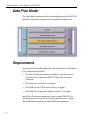
UM-22024-G
DAQ Adaptor
for MATLAB®
Seventh Edition
January, 2009
Copyright © 2005-2009 by Data Translation,
Inc.
All rights reserved.
Information furnished by Data Translation, Inc.
is believed to be accurate and reliable; however,
no responsibility is assumed by Data
Translation, Inc. for its use; nor for any
infringements of patents or other rights of third
parties which may result from its use. No license
is granted by implication or otherwise under any
patent rights of Data Translation, Inc.
Use, duplication, or disclosure by the United
States Government is subject to restrictions as set
forth in subparagraph (c)(1)(ii) of the Rights in
Technical Data and Computer software clause at
48 C.F.R, 252.227-7013, or in subparagraph (c)(2)
of the Commercial computer Software Registered Rights clause at 48 C.F.R., 52-227-19
as applicable. Data Translation, Inc., 100 Locke
Drive, Marlboro, MA 01752
Data Translation, Inc.
100 Locke Drive
Marlboro, MA 01752-1192
(508) 481-3700
www.datatranslation.com
Fax: (508) 481-8620
E-mail: [email protected]
Data Translation® is a registered trademark of
Data Translation, Inc. DT-Open LayersTM,
DataAcq SDKTM, Data Acquisition OMNI CDTM,
LV-LinkTM, and DTx-EZTM are trademarks of
Data Translation, Inc.
MATLAB® is a registered trademark of
The MathWorks, Inc.
All other brand and product names are
trademarks or registered trademarks of their
respective companies.
Table of Contents
Overview . . . . . . . . . . . . . . . . . . . . . . . . . . . . . . . . . . . . . . . . . . . . . . . 5
Data Flow Model . . . . . . . . . . . . . . . . . . . . . . . . . . . . . . . . . . . . . . . . 6
Requirements . . . . . . . . . . . . . . . . . . . . . . . . . . . . . . . . . . . . . . . . . . . 6
Installation. . . . . . . . . . . . . . . . . . . . . . . . . . . . . . . . . . . . . . . . . . . . . . 7
Using the DAQ Adaptor for MATLAB . . . . . . . . . . . . . . . . . . . . . . 8
Analog Input and Output . . . . . . . . . . . . . . . . . . . . . . . . . . . . 10
Setting the Input Type . . . . . . . . . . . . . . . . . . . . . . . . . . . 11
Setting the Synchronization Mode . . . . . . . . . . . . . . . . . 11
Setting the Filter Type . . . . . . . . . . . . . . . . . . . . . . . . . . . . 12
About Channel-Level Properties . . . . . . . . . . . . . . . . . . 13
Configuring the Gain of a Channel . . . . . . . . . . . . . 14
Configuring a Channel for an IEPE Input. . . . . . . . 15
Configuring a Channel for a Thermocouple Input 16
Configuring a Channel for an RTD Input . . . . . . . . 16
MATLAB Property Notes . . . . . . . . . . . . . . . . . . . . . . . . 17
Multiple Subsystems of a Single Type . . . . . . . . . . . . . . . . . . 17
Analog Out Operation Notes . . . . . . . . . . . . . . . . . . . . . . . . . 18
Using Hardware Triggers. . . . . . . . . . . . . . . . . . . . . . . . . . . . . 19
Related Information . . . . . . . . . . . . . . . . . . . . . . . . . . . . . . . . . . . . . 19
3
Contents
4
Data Translation DAQ Adaptor for MATLAB
Overview
This document describes how to install and use the Data Translation
DAQ Adaptor for MATLAB®.
Data Translation’s DAQ Adaptor for MATLAB provides an interface
between the MATLAB Data Acquisition (DAQ) subsystem from The
MathWorks and Data Translation’s DT-Open Layers architecture.
DT-Open Layers provides an API to all of Data Translation’s analog
and digital I/O data acquisition hardware modules. You can use
these two components together to control Data Translation modules
with MATLAB and move data directly into MATLAB for analysis and
display.
Note: Counter/timer operations are not supported in MATLAB
unless they are implemented as part of the analog I/O data stream.
Using these components together, you can create DT-Open Layers
subsystems, add channels to them, and perform single-value or
streaming I/O through them to MATLAB. MATLAB provides
extensive analysis and display features to process the input data and
generate output data.
5
Data Translation DAQ Adaptor for MATLAB
Data Flow Model
The figure below summarizes the relationship between the MATLAB
and Data Translation components in a combined configuration:
Requirements
You must install the following before you install the Data Translation
DAQ Adaptor for MATLAB:
• Your Data Translation hardware module(s) and their drivers
(from the Data Acquisition OMNI CD that ships with your
hardware)
• DT-Open Layers Version 3.0 or higher
• MATLAB Version 7 (R14) Service Pack 3 or higher
• MATLAB Data Acquisition Toolbox Version 2.7 or higher
Install Data Translation components from a recent OMNI CD, or
download from our web site (www.datatranslation.com). Contact
The MathWorks for updates to your MATLAB components.
6
Data Translation DAQ Adaptor for MATLAB
Installation
To install the DAQ Adaptor for MATLAB, do the following:
1.
Click the link for the adaptor on Data Translation’s web site.
2.
Choose Open from the Windows dialog box, or choose Save to
download the file before proceeding. If you chose the save the
file, double-click setup.exe after you download it.
3.
Close other programs if necessary, and click Next on the welcome
screen.
4.
Either change the directory path using Browse or accept the
default directory, and then click Next.
The installer asks you whether to back up replaced files.
5.
Choose the Yes or No radio button, and then click Next.
The installer prompts you to begin file installation.
6.
Click Next.
The installer copies the files to the destination directory.
After the installer copies the files, it launches MATLAB.
MATLAB registers the DAQ Adaptor .DLL using the path you
provided:
>>rehash toolboxcache;daqregister
’C:\PROGRA~1\DATATR~1\DAQADA~1\dtol.dll’;quit
>>
7.
When you return to the installer, click Finish.
7
Data Translation DAQ Adaptor for MATLAB
Using the DAQ Adaptor for MATLAB
The Data Translation DAQ Adaptor for MATLAB is specified as dtol
in MATLAB code. The following example shows how to create an
analog input object (ai0) using the DTOL adaptor for a device at
index 0:
>> ai0 = analoginput (’dtol’, 0)
To add hardware channel 1 to the ai0 object, use the MATLAB
command addchannel, as follows:
>> addchannel(ai0, 1)
To get a single sample from that channel, use the MATLAB command
getsample, as follows:
>> s = getsample(ai0)
You can display the properties of an adaptor (including installed
hardware modules) with the daqhwinfo command. This example
shows how to display the properties of the DTOL adaptor using the
daqhwinfo command:
>> daqhwinfo(’dtol’)
If there are too many devices to display on a single line, you can
assign daqhwinfo to an array and query the name of each device
separately, as shown in this example:
>> x = daqhwinfo(’dtol’)
>> x.BoardNames
8
Data Translation DAQ Adaptor for MATLAB
You can examine properties of a subsystem that you created with the
adaptor by using the MATLAB daqhwinfo command (for built-in
properties) and the get command (for user-settable properties). In
this example, the first command shows all the built-in properties of
the analog input subsystem (ai0) and the second command shows all
the DTOL user-settable properties of the analog input subsystem
(ai0):
>> daqhwinfo(ai0)
>> get(ai0)
You can find out more information about a property using the
MATLAB propinfo command. For example, this command shows
how to get information about the GainPerChan property that is
associated with channel 1 of the analog input subsystem (ai0):
>> propinfo(ai0.channel(1),’GainPerChan’)
To control a data acquisition session, issue MATLAB commands and
set the appropriate DTOL properties, described in the following
subsections. For more information about using MATLAB commands
and MATLAB Data Acquisition Toolbox properties, refer to your
MATLAB documentation.
9
Data Translation DAQ Adaptor for MATLAB
Analog Input and Output
The Data Translation DAQ Adaptor for MATLAB provides the
following adapter-specific properties for analog I/O operations:
Table 1: Adaptor-Specific Analog Input/Output Properties
Property
Description
A/D D/A
FIFOAvailable
Determines if a FIFO is available on the subsystem.
No
Yes
FIFODepth
Determines the size of the FIFO.
No
Yes
OutOfDataMode
Specifies how to handle an out-of-data condition. Set
No
Yes
Determines if the subsystem uses binary encoding.
Yes
Yes
SupportExternalTriggerFalling Checks for external, falling-edge triggering support.
Yes
Yes
SupportExternalTriggerRising Checks for external, rising-edge triggering support.
Yes
Yes
SupportGainPerChannel
Yes
Yes
Yes
Yes
Yes
Yes
Yes
No
Yes
No
Yes
No
Hold to use the last value in the output buffer. Set
Default to use the channel-specific Default Value
property.
SupportBinaryEncoding
Determines if the subsystem supports different gain
values for each analog channel.
SupportSoftTrigger
Determines if the subsystem supports an internal
software trigger.
SupportTwosComp
Determines if the subsystem uses twos complement
encoding.
ReturnCjcTemperatureIn
Specifies whether to return CJC values in the analog
Streama
input data stream.
SyncMode
Specifies the synchronization mode (None, Master, or
Slave) for the analog input subsystem of the device.
DataFilterTypea
Specifies the filter type (Raw or MovingAverage) for the
analog input subsystem of the device.
a. This property is visible only when a TEMPpoint or VOLTpoint instrument is specified.
10
Data Translation DAQ Adaptor for MATLAB
Setting the Input Type
To specify whether a subsystem uses differential or single-ended
input channels, use the MATLAB property inputtype. For example,
this command configures the analog input subsystem (ai0) to use
differential input channels:
>> ai0.inputtype=’Differential’
To configure the analog input subsystem (ai0) to use single-ended
channels, use this command:
>> ai0.inputtype=’SingleEnded’
You can use the get(ai0) command to see the changes. When you
change input types, the channel list also changes.
Setting the Synchronization Mode
Some devices provide a synchronization connector (such as an LVDS
RJ45 connector) that allows you to synchronize operations on
multiple devices. In this configuration, the subsystem on one device
is configured as the master and the subsystem on the other device is
configured as a slave. When the master module is triggered, both the
master device and the slave device start operating at the same time.
If the device allows you to program the synchronization mode
(SupportSynchronization is True), use the DTOL-specific property
SyncMode to set the synchronization mode to one of the following
values:
• None – The subsystem is configured to ignore the
synchronization circuit on the device.
• Master – Sets the subsystem as a master; the synchronization
connector on the device is configured to output a synchronization
signal.
11
Data Translation DAQ Adaptor for MATLAB
• Slave – Sets the subsystem as a slave; the synchronization
connector on the device is configured to accept a synchronization
signal as an input.
The following command sets the synchronization mode of the analog
input subsystem to Master:
>> ai0.SyncMode=’Master’
Setting the Filter Type
Some devices, such as TEMPpoint and VOLTpoint instruments,
support a software-programmable filter type for the analog input
subsystem. For these devices, the following filter types are available:
• Raw – No filter. Provides fast response times, but the data may be
difficult to interpret. Use when you want to filter the data
yourself.
The Raw filter type returns the data exactly as it comes out of the
Delta-Sigma A/D converters. Note that Delta-Sigma converters
provide substantial digital filtering above the Nyquist frequency.
Generally, the only time it is desirable to turn off the software
filter is if you are using fast responding inputs, sampling them at
higher speeds (> 1 Hz), and need as much response speed as
possible.
• MovingAverage – Provides a compromise of filter functionality
and response time. This filter can be used in any application.
This low-pass filter takes the previous 16 samples, adds them
together, and divides by 16.
The following command sets the filter type of the analog input
subsystem to MovingAverage:
>> ai0.DataFilterType=’MovingAverage’
12
Data Translation DAQ Adaptor for MATLAB
About Channel-Level Properties
The following properties appears at the channel level after you add a
channel:
Table 2: Adaptor-Specific Channel Property
Property
Coupling
Description
For devices that support IEPE inputs, specify the
A/D D/A
Yes
No
Yes
No
Yes
No
coupling type (AC or DC) for a particular analog input
channel.
ExcitationCurrentSource
For devices that support IEPE inputs, specify the
excitation current source for a particular analog input
channel. Possible values are Internal (excitation current
source is on the device), External (excitation current
source is external to the device), or Disabled (no
excitation is applied).
GainPerChan
Specify the gain value for a particular analog input
channel.
13
Data Translation DAQ Adaptor for MATLAB
Table 2: Adaptor-Specific Channel Property (cont.)
Property
ThermocoupleType
Description
Specify the thermocouple type for a particular analog
A/D D/A
Yes
No
Yes
No
input channel. The following thermocouple types are
supported: J,K,B,E,N,R,S,T, or None.
If you specify 'None' for the ThermocoupleType, data is
read as voltage from the corresponding channel and the
UnitRange reflects the voltage range supported by the
device.
If you specify a value other than 'None' for the
ThermocoupleType, data is read as temperature from
the corresponding channel and the UnitRange reflects
the temperature range, in degrees C, of the specified
thermocouple type.
Data read using Getdata and Getsample is returned in
floating-point format.
RtdType
Specify the RTD type for a particular analog input
channel. The following RTD types are supported: Volts,
Ohms, PT100_385, PT500_385, PT1000_385,
PT100_392, PT500_ 392, PT1000_392
Configuring the Gain of a Channel
Use the DTOL-specific GainPerChan property to set the gain for a
channel. For example, this command sets the gain for the first channel
(channel 0) of the analog input subsystem (ai0) to 4:
>> ai0.channel(1).GainPerChan = 4
14
Data Translation DAQ Adaptor for MATLAB
Note: DT-Open Layers uses a per-channel gain concept, which
differs from MATLAB’s range based per channel setting to control gain
and range. You can specify a per-channel gain, or the adaptor
attempts to set the best per-channel gain for a specified range.
We recommend using the GainPerChan property for per-channel
gain control.
Configuring a Channel for an IEPE Input
Use the DTOL-specific properties ExcitationCurrentSource and
Coupling to the configure a channel for an IEPE input. For example,
the following commands configure the first channel (channel 0),
which is associated with the analog input subsystem (ai0), for an
IEPE input that uses an internal excitation current source and AC
coupling:
>> ai0.channel(1).ExcitationCurrentSource=
’Internal’
>> ai0.channel(1).Coupling=’AC’
To configure the same channel for an IEPE input that uses an external
excitation current source and DC coupling, use these commands:
>> ai0.channel(1).ExcitationCurrentSource=
’External’
>> ai0.channel(1).Coupling=’DC’
To disable the excitation current source for the same channel, use this
command:
>> ai0.channel(1).ExcitationCurrentSource=
’Disabled’
15
Data Translation DAQ Adaptor for MATLAB
Configuring a Channel for a Thermocouple Input
Use the DTOL-specific property ThermocoupleType to the configure
a channel for a thermocouple input. For example, the following
command configures the first channel (channel 0) that is associated
with the analog input subsystem (ai0) for a J type thermocouple
input:
>> ai0.channel(1).ThermocoupleType= ’J’
The UnitRange property for that channel will then reflect the
temperature range, in degrees C, of the J type thermocouple input.
Data read using Getdata and Getsample is returned in floating-point
format.
Configuring a Channel for an RTD Input
Use the DTOL-specific property RtdType to the configure a channel
for an RTD input. For example, the following command configures
the first channel (channel 0) that is associated with the analog input
subsystem (ai0) for a Platinum 100 Ω RTD input with an alpha
coefficient of 0.003850:
>> ai0.channel(1).RtdType= ’PT100_385’
The UnitRange property for that channel will then reflect the
temperature range, in degrees C, of the RTD input.
Data read using Getdata and Getsample is returned in floating-point
format.
16
Data Translation DAQ Adaptor for MATLAB
MATLAB Property Notes
The following adaptor-specific notes apply to MATLAB properties:
Table 3: Adaptor Notes for MATLAB Properties
MATLAB Property
BufferingConfig
Notes
The minimum buffer size is 128, but for best performance, set to
1024 or greater.
NOTE: If the value for RepeatOutput is greater than 1, the buffer size
must be an integer multiple of the number of samples queued. The
adaptor warns you of this when you change RepeatOutput.
TotalChannels
This may include channels that are in two lists and have a mode
(single-ended vs. differential). Also, when the InputType is changed
from SingleEnded to Differential, the channel IDs will change in the
DaqHwInfo() listing.
TriggerCondition
Either "RisingEdge" or "FallingEdge" depending upon what the
module supports.
Multiple Subsystems of a Single Type
To provide access to all elements of a device with multiple
subsystems of a particular type (for example, multiple analog input
subsystems, such as on the DT9822), the adaptor creates virtual boards.
The first board enumerated includes any other types of subsystems.
17
Data Translation DAQ Adaptor for MATLAB
For example, the DT9822 module enumerates in the adaptor like this:
’DT9822(01)’
A/D, D/A, Digital I/O
’DT9822(01)-1’
A/D
’DT9822(01)-2’
A/D
’DT9822(01)-3’
A/D
To access the fourth A/D subsystem, use the virtual board
’DT9822(01)-3’ and its one analoginput() object.
Analog Out Operation Notes
The following caveats apply to analog output operations:
• The number of samples output will not always be correct,
particularly when the samples to output are not the same as the
buffer size. This is because DT-Open Layers sends the whole
buffer to the D/A converter, and the adaptor pads the output
buffer to either the Hold value or the channel default value (see
“OutOfDataMode”).
• DT-Open Layers does not send a message when the actual
hardware trigger occurs. Therefore, the time and sample count
for the trigger event will not be correct for
TriggerType=’HwDigital’ for analog out.
• The final voltage on a D/A output might be unpredictable after a
streaming operation.
18
Data Translation DAQ Adaptor for MATLAB
Using Hardware Triggers
To use a hardware trigger for analog output operations, set the
TriggerType to ’HwDigital’ and set the TriggerCondition property to
Rising or Falling.
When the analog output subsystem is started, data buffers may be
sent to the hardware FIFO, resulting in a "buffer done" message to the
adaptor and a trigger event before the D/A output value has been
set. Therefore it may appear that data output occurs before the
hardware trigger happens, but the data has only been moved to the
board FIFO, not output through the D/A converter.
Related Information
Refer to the following documents from Data Translation for more
information on using DT-Open Layers:
• DataAcq SDK User’s Manual (UM-18326). For programmers who
are developing their own application programs using the
Microsoft C compiler, this manual describes how to use the
DT-Open LayersTM DataAcq SDKTM to access the capabilities of
Data Translation data acquisition devices.
• DTx-EZ Getting Started Manual (UM-15428). This manual
describes how to use the ActiveX controls provided in DTx-EZTM
to access the capabilities of Data Translation data acquisition
devices in Microsoft Visual Basic® or Visual C++®.
19
Data Translation DAQ Adaptor for MATLAB
20