1
Stanislav Shults
DEVELOPMENT OF INTELLEGENT
MOBILE PLATFORM
Part of Decartus project
Bachelor’s Thesis
IT Department
May 2011
1
DESCRIPTION
Date of the bachelor's thesis
27.05.2011
Author
Degree programme and option
Stanislav Shults
Information Technology
Name of the bachelor's thesis
Development of intelligent mobile platform
Abstract
Unmanned vehicles are used in many areas related to security systems and defence. Our team create
an UGV under the Decartus project. This system provides quality video surveillance system with
built in autopilot system and remote control over the Internet. The objective of my thesis was to designed and prototype intelligent mobile platform with a possibility of data exchange with PC over 1
km range. The secondary objective was to create and implement autonomous navigation system
based on GPS technology.
I started my work getting to know with different types of mobile platforms with main attention on
wheels type. Then I focused on GPS system and methods direction calculation. In order to improve
navigation system I looked for a compass module and programmed it. After that I searched market
for distance sensors and robotic video cameras. Next step was to establish wireless connection between the platform and the PC. Finally I prototyped the mobile platform.
This kind of system can be easily used for any unmanned vehicles with appropriate configurations
depending on purposes to use. These systems are mostly used in defence, security and research areas.
I found various mobile platform models, GPS receivers and robotic cameras and chose most suitable
ones for Decartus system. Then I did numerous experiments, implementations and reached good
results. This system provides stable wireless data communication with PC and programmable
autonomous mode. It can follow the pre-defined path, avoid obstacles and return to the starting point,
in case connection loss. This platform can be equipped with different sensors in order to provide additional information. From my point of view this system can be very useful in the future when people
can use it in dangerous situation and places without any risk for their health.
Subject headings, (keywords)
Decartus system, autonomous navigation, AVR microcontroller, GPS, Ultrasonic sensors, Compass,
mobile platform.
Pages
Language
70 pages + attachments 47 pages
Enlish
URN
Remarks, notes on appendices
Part of Decartus progect, mobole platform design, buld Autonomous Navigation System
Tutor
Employer of the bachelor's thesis
Koivisto Matti
Mikkeli University of Applied Sciences
2
CONTENTS
1
INTRODUCTION ............................................................................................................... 1
2
THEORY OF MOBILE SURVELIANCE SYSTEM
3
2.1
Video surveillance system ......................................................................................... 3
2.2
Mobile platforms ........................................................................................................ 4
2.3
GPS navigation .......................................................................................................... 7
BUILDING BLOCKS OF MOBILE PLATFORM .......................................................... 12
3.1
Microprocessors ....................................................................................................... 12
3.2
Sensors ..................................................................................................................... 14
3.2.1 Ultrasonic ..................................................................................................... 14
3.2.2 GPS receiver................................................................................................. 15
4
5
3.3
Data transceivers ...................................................................................................... 17
3.4
Video camera ........................................................................................................... 19
3.5
Video transmitter ..................................................................................................... 20
3.6
USB-COM converter ............................................................................................... 21
3.7
Servo drivers ............................................................................................................ 22
3.8
Platform.................................................................................................................... 23
3.9
Power ....................................................................................................................... 24
IDEA AND GOALS ......................................................................................................... 25
4.1
Basic idea ................................................................................................................. 25
4.2
Expected technical parameters ................................................................................. 27
HARDWARE .................................................................................................................... 28
5.1
Ultrasonic sensors .................................................................................................... 28
5.2
Compass module ...................................................................................................... 30
5.3
GPS module ............................................................................................................. 31
5.4
Data transceivers ...................................................................................................... 34
5.5
Video transmitter ..................................................................................................... 39
5.6
Video camera ........................................................................................................... 40
5.7
USB-COM converter ............................................................................................... 41
5.8
Servo drivers ............................................................................................................ 42
5.9
Mobile platform ....................................................................................................... 43
5.10 Embedded microcontrollers ..................................................................................... 44
5.11 Wireless PC block .................................................................................................... 46
3
5.12 Power system ........................................................................................................... 47
5.13 Principal scheme description ................................................................................... 48
6
7
SOFTWARE ..................................................................................................................... 50
6.1
Basic algorithm ........................................................................................................ 52
6.2
Sensors scanning ...................................................................................................... 53
6.3
Data communication ................................................................................................ 55
6.4
Platform movement control ..................................................................................... 59
6.5
Autopilot system ...................................................................................................... 61
CONCLUSSION ............................................................................................................... 64
BIBLIOGRAPHY
ATTACHMENT 1
ATTACHMENT 2
ATTACHMENT 3
ATTACHMENT 4
4
1 INTRODUCTION
Nowadays there is a great variety of different surveillance systems, which can help people to
control different kind of objects and areas. Also, these systems make it possible to take care of
people or opposite way, spy something.
It‟s a really great opportunity, when people can
discover and see whatever they want without being themselves in present. This kind of system
is commonly used by police, sappers and army in dangerous situations. As students of Mikkeli UAS we decided to set up “Decartus” project in which we implement an improved mobile video surveillance system with advanced features, such as autopilot based on GPS system, ability to control it over the Internet, comfortable robot navigation by operator and reliable platform with confident cross country characteristics. This project also includes a server
to control and represent information for user from mobile platform and web-access to this
server with the same abilities for operator. First part will be done by Ivan Suvorov and second
by Vitaliy Klimenko, also Mikkeli UAS students.
My final thesis is related to hardware part of the Decartus project. It will be a bit complex
system which includes a GPS module, ultrasonic sensors in order to avoid obstacles, mobile
platform, a connection between a PC and a main microcontroller which will organise all of
this.
This device should have ability to cover quite a big area. Maximum distance from the server
is 1.5 km. It would be enough for doing different kind of work. Speed of mobile platform
must be up to 30 km/h in order to give ability for operator to control large enough area in
short period of time. Controlling block should be quite compact and located near the computer. With such features we will have useful and convenient system for video surveillance.
For Autopilot system we will use a GPS module, which sends the information to microcontroller and operator. Here we will use parallel processing both on server and on microcontroller. This method would help us to avoid situations when operator could lose signal and as result lose our bot. So, the system independently from the server calculate backup path and return bot. Moreover with such a method this system can be totally independent, just drive
around, collect some data, return and transfer it to the server. In order to avoid obstacles there
must be installed ultrasonic sensors with 3m work range.
1
After that, special algorithm will recalculate path with the new circumstances. Such a system
will meet the high standards of quality and reliability. It is also will help to save peoples‟ life
and do dangerous work safer.
Such designing system can be implementing not only for ground robots, but also for Unmanned Aerial Vehicles (UAV). Because, they use navigation system to determine their location on the Earth, object location and differ military operations. Our system also has installed
portable onboard camera, which is also key element of UAV‟s systems. So, video surveillance
might be organized from the air, what is more efficient in some cases then ground one.
The structure of my thesis is follows. First in Chapter 2 I introduce the use and development
of video surveillance systems. The aim of the chapter is to introduce the reader to different
application areas of video based surveillance. In Chapter 3 I present the common building
blogs of mobile surveillance systems including microcontrollers, sensors, radio transceivers
and GPS module. Chapter 4 describe main idea of the intelligent mobile platform for Decartus
system and provide expected technical characteristics. Chapter 5 was done with the aim of to
describe and explain working principle of used devices. In the last one Chapter 5 reader find
software description for embedded microcontrollers. In the last chapter 6 I mentioned some
details related to software and ways of data communication between MCs and PC.
2
2 VIDEO SURVEILLANCE SYSTEMS AND MOBILE PLATFORMS
2.1 Video Surveillance Systems
Over the past ten years, video surveillance systems have become an integral part of an integrated security system, which helps to prevent threats and protect the security of the property.
A modern video surveillance system provides users with place observation and picture recording functions, and they also include intelligence algorithms which can help to recognise
different object and predict some events [1]. Such systems are widely used in every sector.
They face challenges in protecting their customers, employees, production facilities, enhance
productivity and security. During past several years number of terrorist attacks has increased
dramatically. That is why governments from around the world turned their forces to improve
quality of society security. First of all it takes an effect on public places such as airports, subways and railway stations. For instance, London Underground and Heathrow Airport have
more than 5000 cameras each [2]. Surveillance systems created for commercial purposes differ from civil CCTV systems. Because, commercial systems tend to use some specific equipment and they widely use networks of digital intelligent cameras.
There are two types of video surveillance systems: analogue and digital. Analogue video surveillance systems have been widely used in small areas, where transferring information by
path “Camcorders – VCR” would be enough to organise quite sufficient security of image
transition and later viewing of stored data. Currently, the surveillance system installed analogue cameras are simple to implement with a low price. These cameras are optical devices,
and they generate video signals when light flux passes through their lens and came to the
CCD matrixes where the electrical signal is created [3].
Digital CCTV systems have a similar kind of a structure, and the main difference in comparison to analogue one is in cameras. Digital cameras have additional AD converter, so, all transferred data is in digital format. With increasing popularity of LANs and Internet such systems
will has a great potential to provide the most convenient and secure method of video surveillance[4].
3
2.2
Mobile Platform
Today we can see a great verity of mobile platforms (MP) for mobile robots. It depends on
which purposes robot was developed and in which circumstances it should work. There exist
lots of different robots as for civil as for military area. Different kind of robots are designed
for defence services and they have more complex controlling systems with enhanced algorithms and they use special platforms with highest cross country characteristics. Also electronics which they use are much better, with lower power consumption and highest data transition rates which helps to reach better results.
Civil robots are usually used for household purposes [5], such as grass-cutter, home and pool
vacuuming and gutter cleaning. Some examples are shown in Figure 1. Vacuum cleaner robots use specially designed platform with low clearance with 3-4 wheels and special sensors
to avoid obstacles and they have low height in order to be able work under the furniture. Their
bodies are typically made of plastic and controlling system are not waterproofed. Their controlling systems help them to work totally automatically without any human help.
Figure 1 – Scooba (home vacuum), Looj (gutter cleaner) and Verro (pool cleaner) by iRobot.
[5]
Unlike Scooba robot, Verro has water resistance body which helps it to work under the water
surface. Such kinds of platforms are commonly used for robots which work under the water
with the aim of to protect electronic damage. Actually it doesn‟t matter what robot doing
there, cleaning, researching or scanning bottom it should be water protected.
4
Figure 1 also provide example (Looj) of design for robot which work under special conditions, namely in narrow gutters and good traction. So, as result we can see narrow body with
two tracks on the side. Such design helps to placed it in narrow trenches and overcome the
difficult parts. Because these robots are oriented to domestic use in the normal catch their
platforms are made of plastic what is dramatically reduces the cost of the product.
In military and defence area there are two totally different classes of mobile platforms, for
ground and air purposes. They are fundamentally different from each other with design as
intended for totally differs condition to use. Each of them has their own special characteristics
to ensure the reliability and stability under certain conditions.
As it is well known military equipment is used in harsh conditions that require high dust,
moisture and thermal protection from designed mobile platform. Moreover, it should have
light weight and optimized size for convenient transportation under hard conditions.
(a)
(b )
Figure 2 – a) TALON Small Mobile Robot, b) iRobot 510 PackBot. [9] [5]
It‟s clearly seen in Figure 2 that TALON and iRobot use tracked platform. Such solution enables to reach high cross country characteristics. Let‟s take a look to description of these robots. TALON is a lightweight, powerful, versatile robot designed especially for missions
ranging from reconnaissance to weapons delivery. It's big, quick-release cargo bay accommodates a variety of sensor payloads, making TALON a one robot solution to a variety of mission requirements [6].
5
Next, is one of the most successful battle-tested robots in the world, the iRobot 510 PackBot
performs bomb disposal and other dangerous missions for war fighters and first responders.
510 PackBot can easily climbs stairs, rolls over rubble and navigates in narrow passages with
sure-footed efficiency, driving at speeds of up to 5.8 miles (9.33 km) per hour [7]. Such platforms provide high efficiency, reliability and stability under extreme conditions. They also
allow the robot to move through difficult terrain and reach hard available or dangerous places.
Another generation of robots it is unmanned aerial vehicle (UAV; also known as a Unmanned
Aircraft System (UAS)) – aircraft which is flying without pilot by using different systems of
navigation, such GPS or GLONASS. They are used from small and autonomous Special
Forces units, in army battalions, divisions, brigades and corps, to joint services theatre operations centers UAS provide a wide range of combat support services, such as defence and exploration objects from the air. It‟s really convenient to use, because of light weight, small resources consumption and high resolution of video camera, which provide quality picture of
the survive area [8].
Figure 3 - Unmanned Aircraft Systems [10]
It can be clearly seen in Figure 3 that the design of UAV use glider technology. This allows
minimizing power consumption while providing video surveillance. UAV should be optimized for speed in order to provide fast transportation time to the survive area and also they
should be able to stay at that area as long as they need. For the last purposes slow speed
6
would be recommended. However, we know that lower speeds require bigger wings. Using
glider technology with huge wings they can reach great characteristics in this field.
Moreover, as they do not need pilot inside there is no problems with overload for human. Because UAV is a remote control machine, an operator can stay on the ground and control it
through special equipment, which provide similar systems as in real plain. Some of these
UAVs are so simple that even common solder can operate them, but some of them so complex
that they need special employee with special skills to manage them.
Al in all, before developing or buying such systems we should to clearly understand where
such platform will be used and under which conditions. Because with the right decisions we
can reach great results, and overcome the obstacles and problems that appear in our way.
2.3
GPS Navigation
Navigation is one of the most important services for determine the object position relatively to
the earth's surface. It helps to realise what is your location now and where is the point which
you should reach. Since ancient times there has been great verity of differ devices and methods for navigation. However, they do not provide accurate enough results, because nowadays
requirements for navigation have grown up dramatically.
To solve this problem there has been developed great verity of navigation systems using satellite technology. The main idea here is to measure distance between object with known location (satellites) to the object which is need to be determined [11]. Satellite sends the signal to
the receiver and distance measure according to delay between sending and receiving. In order
to find out longitude and latitude it would be enough to get a signal from at least three points.
After that receiver can geometrically calculate it‟s own location.
In Figure 4 it can be seen how satellite navigation works. There are three satellites with different locations and an object which should determine its own location. This object has a special receiver. Each satellite sends the signals to their own area on the earth. The receiver takes
those signals and calculates what is the accurate distance to the each of the satellite. Using
that information it applies special algorithms which provide precise determination of object‟s
coordinates. It uses at least three signals to calculate that because only in this case in 2D space
7
we can calculate more or less accurate object location. The same principal is used for GSM
navigation (AGPS). In that case it uses at least three base stations of mobile operators to calculate distance to the object. But this system isn‟t so accurate (error ~100m) [12].
Figure 4 – Satellite navigation [12]
Most of the big and developed countries in the world have designed their own navigation systems, mainly for the military purposes. The reason for this is obvious. For example Russia
can‟t use American negation system because it might be controlled by the US army and it can
cause lots of problems for Russians and wise versa.
Various of navigation systems in used or development are [13]:
Galileo – a global system being developed by the European Union and other partner countries, planned to be operational by 2014.
Beidou – People's Republic of China's regional system, covering Asia and the West Pacific.
COMPASS – People's Republic of China's global system, planned to be operational by
2020.
GLONASS – Russia's global navigation system.
IRNSS – India's regional navigation system, planned to be operational by 2012, covering
India and Northern Indian Ocean.
8
QZSS – Japanese regional system covering Asia and Oceania.
GPS – USA Global Position Navigation system, nowadays one of the most widely spread
around whole the world.
Although there are many alternative the most widely used navigation system is GPS. It was
developed by U.S. military, owned and operated satellite constellation [11].
It can be apply
everywhere in civil and commercial sector far outweigh it‟s original military purposes, and
service continue to grow. GPS was developed as a generic navigational system, but has
evolved into a predictable, reliable, and ubiquitous capability of “information on demand”.
However it is used for wide-ranging purposes and requirements. Anyway, it is a transformational tool that has dramatically spread our society, economy, and national security. For sure,
it would be difficult, or might be impossible, to imagine a world without GPS.
As in air transport as in air forces for military purposes it‟s so vital to use such a system. This
is due to that fact, that both of them move to the huge distance, and they use also autopilot
system which can control whole plane or helicopter according to the flight plan.
GPS navigation system has 24 satellites on the earth orbit, with the aim of to provide continuous navigation without interrupts. Satellites travel with the speed of 3.9 km/s on the orbit that
is why a circulation time of 12h sidereal time, corresponding to 11 h 58 min earth time. It
means that same satellite reaches same position around 4 minutes later, every day. Average
distance from the Earth canter is 26560 km, with the average Earth radius of 6360 km, so the
height of the orbit is 20200 km. However, it‟s called as “medium satellite orbit”. For instance
such systems as ASTRA or Meteostat has 42300 km orbit. [14]
Satellites located on six planes, each of them can contain four places where satellites can be
located equidistantly. Nowadays, angle between planes (inclination angle) 55 degree, these
planes are rotated in the equatorial plane by 60 degree against each other. It means that the
orbits dispose from 55 N to 55 degrees S. By such arrangement it can be guaranteed that at
least 4 satellites can be reached all the time, whole around the world. Due to that fact that,
satellite‟s orbits run far enough to the north and south it can be reached even on the poles.
However, accuracy there is not so precise, because then closer you come to the poles, then
lower above the horizon the satellites are located [14].
9
GPS system is based on data transmitted between satellites and receivers, that is why it‟s need
it‟s own frequency band where it can operate. All satellites in this system broadcast data in
two carrier signals in the microwave range [14]:
L1 – 1.57542 GHz (19.05 sm). It‟s transferring only SPS code, standard code for navigation in civil area (navigation error ~3-5m).
L2 - 1.2276 GHz (24.45 sm). This one is transferring the P code which has accurate navigation data. This type of receiver is used only in military area for precise navigation of
rockets and bombs (~1-3sm).
In Figure 5 we can see an example of P code which is
transferred for military receivers. Right hand circular polarized signal is used for transferring such code. Figure 5 also shows that it has a transmission speed equal to
10.23*10^6
Bits/s and 6*10^12 Bits per satellite.
Figure 5 – P-code example [15].
There are three types of signal modulation: Amplitude Modulation (AM), Frequency Modulation (FM) and Phase Modulation (PM). GPS system uses Phase Modulation the most popular
modulation technique. Figure 6 shows the composition of signals which are transmitted by
GPS-satellites. This graph shows that L1 signal and L2 signal consists of several signals. It
can be clearly seen that L1 consist on carrier 1575,42 Mhz, C/A Code 1.023 MHz an P-Code
10.23 MHz. Whereas L2 consist of P-Code and carrier 1227,6 MHz. But also both of them
include NAV/System Date 50 Hz signal.
10
Figure 6 - Composition of GPS signals [14].
The satellite communication network uses a CDMA spread-spectrum technique. The low-bit
rate message data is encoded with a high-rate pseudo-random (PRN) sequence that is unique
for each satellite. GPS receiver should know, what are the PRN codes for each satellite to
restore original data message data.
11
3. BUILDING BLOCKS OF MOBILE SURVEILLANCE SYSTEM
As mentioned earlier I am responsible for the hardware part of the Decartus project. Therefore
in this chapter I introduce the most important components required to implement mobile surveillance systems.
3.1 Microcontrollers
As we know nowadays more or less sophisticated electronic devices use microcontrollers. It is
a special microcomputer designed to control various electronic devices and the implementation of the interaction between them according to the program. In contrast to the microprocessors used in personal computers, microcontrollers have built-in accessories. These devices
perform their task under the control of microprocessor code of microcontroller [16].
The most common included devices are built-in memory, Input/Output ports (I/O), timers,
system clock and communication interfaces, such as UART, I2C and ISP. Memory devices
include random access memories (RAM), read only memories (ROM), flash ROM (EPROM),
electrically reprogrammable ROM (EEPROM). Timers and intrfaces include real-time clock
and timer interrupts. Tools I/O includes analogue converters (A/D), digital to analogue converters (D/A), liquid crystal display driver (LCD) of vacuum fluorescent display (VFD).
Embedded devices have improved reliability, because they do not need any external electrical
circuits.
Microcontrollers can be found in huge quantities in modern industrial and household products
like in machine tools, automobiles, telephones, televisions, refrigerators, washing machines
and even coffee makers. Among microcontrollers manufactures there are Intel, Motorola, Hitachi, Microchip, Atmel, Philips, Texas Instruments, Siemens and many others.
The main classification feature for microcontrollers is the type of the data. On this basis, they
are divided into 4-, 8-, 16-, 32- and 64- bit classes. Today, the largest part of the world market
belongs to the 8-bit microcontroller devices (about 50% in value terms). This is followed by
16-bit microcontrollers and DSPs (Digital Signal Processor) aimed for use in signal processing system (each group has about 20% of the market). Within each group of microcontrollers
they can be divided into CISC- and RISC- device. Earlier CISC microcontrollers were the
12
largest group, but in recent years, there has been a clear trend of growth in the RISC architecture [17].
Clock frequency or, more precisely, the bus speed determines how many calculations a microcontroller can perform per unit time. In general the performance of the microcontroller and
the power consumed by it increase with clock frequency. Performance of the microcontroller
is measured in MIPS (Million Instructions per Second).
One of the most widely spread family of microcontrollers is AVR by Atmel Company. MCU
in this family are 8-bit microcontrollers for embedded applications. Microcontrollers made by
low-power CMOS (Complementary-symmetry/metal-oxide semiconductor) technology combined with advanced RISC – architecture achieve the best combination of the performance
speed/power consumption. Due to the fact that the vast majority of commands are executed in
one clock cycle, the performance of these microcontrollers can reach values of 1 MIPS at
1MHz clock frequency. The family includes the classic microcontrollers with various combinations of peripheral devices with varying levels of built-in memory and different pin count.
Such diversity gives the developer opportunity to make the best choice and use exactly the
microcontroller, which is best suited to its needs. Figure 6 shows typical bodies for AVR microcontrollers. The selection of the microcontroller depends on features and purposes of use.
If there is no limitation of the size, device can use DIP body, moreover it is simple to use
while designing new devices. But if smaller size is required SMD body can be used without
any loss in performance.
Figure 6 – AVR family microcontrollers [18].
13
3.2 Sensors
Robots don‟t have eyes, ears or skin which help human to realise distance to the objects, colours, understand sound, temperature, pressure and other external world parameters. These
features help us to navigate and analyze the space around us. However, robots, to be able to
see and interact with the world, need same type of sensors, as human has.
With the aim to
measure each parameter there are several methods how to do that. So, sensor choice should be
based on type of the robot, and what kind of aim it‟s going to follow.
3.2.1 Ultrasonic sensors
Ultrasonic sensors are switching devices that are used for determine the distance to the object
in the non-contact way. To measure a distance they use special ultrasonic sound (40 kHz),
which is sent in a short time slot by transmitter. Then, as a normal sound it reflects from the
object and comes back to receiver. Distance is determined by calculating the time between
sending and receiving pulses [19]. Figure 7 shows how standard ultrasonic sensor works. It
can be seen how sound goes from the transmitter, to the object and finally back to the receiver.
Figure 7 – Ultrasonic work principal [20].
Such a kind of sensors can be used for wide range of purposes, such as:
Distance measurement
Counting objects
Determining the diameter
Availability control
Crash protection
Determination of the contour
14
The operation angle and distance in common sensor varies from 20 to 25 degree and 200 –
500 sm respectively. These parameters are good enough for lots of purposes, from civil to
production area.
The main advantage of ultrasonic sensors is that they can detect almost any kind of material.
Moreover, they have total tolerance to pollution in their working environment. It is obvious,
that intelligent ultrasonic meters are really important for solving the problems of automation
of technological processes and determine the distance and the object's position in various industrial sectors.
3.2.2 GPS Receiver
Navigation is one of the most important features for autonomous systems.
It helps to realise
and determine position in the external environment. There are lots of systems which can help
us to do that, but for global orientation, the widely spread satellite systems introduced in the
previous section are the natural choice.
In this project we are going to work with GPS navigation system. There are lot of special devices that might be used for receiving satellite signals. Searching through the market we were
able to find great virility of GPS receivers, which can be used in different areas. It‟s easy to
find receivers with accuracy in the range of ~2-5m, but they have limitations: velocity
18000m max. and maximum speed is 515m/s. However, there is also a receivers which give
~3-30sm accuracy without any limitations, which are usually used in military and space area.
The last one, which is able to receive special P code, with accurate GPS data impossible to get
by a common student. For project related to robotic area it would be justified to use small
GPS modules which can give us necessary information for navigation.
All of such receivers use special protocol and interface for communication with external devices. A protocol which is used for these purposes is called NMEA 0183, and a typical GPS
receiver uses RS-232/422 electrical interface. These technologies were applied with aim of to
provide ease connection between devices. All microcontrollers, even simplest one, has at least
one RS-232(UART/COM) interface, which is allows combine and design huge range of devices with differ features and purposes [21]. The idea of NMEA protocol is to provide data
15
exchange between GPS module and device. There are several groups of information and each
of them has its own header. The most popular groups of data, which can be sent by GPS receivers has such header as: GGA, GLL, GSA, GSV, RMC and VTG. Each of them provides
different information about the receiver position. The most important metrics are time, latitude, longitude, speed and course over ground. This information will make a system able to
navigate over the whole world without any problems, and it will never be lost.
Figure 8 – GPS modules [22]
Let‟s take a look to examples of such GPS modules which can be easily used in autonomous
systems. Figure 8 provide examples of onboard chip solutions. It can be clearly seen that
some of them are as small as a coin. It makes possible to install them in devices with limited
space, even to mobile phones and laptops [22].
Modern mobile systems are based on powerful chips, performance of which is increasing
highly every half year and they have reached hundreds of thousands operations per second.
For such systems it is not an issue to receive and calculate GPS data. These systems have also
special software such as GPS pointer or GPS maps show the user location. Moreover, these
applications can also provide information how to reach certain place in the city by car, walk,
train and other means of transport. A user just puts the coordinates of the destination and the
rest of work is done by a mobile system. These systems are also widely used at shipping area.
When you are in the open sea and there is just water around, you should be able to understand
where you are and where you have to go in order to reach a correct place. So, a satellite navigation system like GPS can provide information about current location of yours in all weather
16
conditions. Time delay between renewable data from 0.2 to 1 sec. Such frequent information
updating, allows accurate navigation around whole the world.
3.3 Transceivers
In wireless systems the most important part is to solve a data transmitting problems. In order
to do that special transceivers and receivers should be used. The selection of the right components depends on where we are going to use them and what requirements should be meet.
There are such devices which combine both, transceiver and receiver in one. This kind of solution helps to save a space in electronic devises by building both of them only in one chip,
like in ZigBee technology. Decartus project requires modules which can support transmission
of relatively small amount of information. So, let‟s take a look at examples of transceivers
which we can use with the aim to provide such connection with using RS-232 interface for
long distance (~1km).
Figure 9 – range of different transceivers: a) YS-1100U RS485, b) HM-TR433-232, c) SpiritON: TR24A, d) XBee Pro Series 2 [23][24].
Figure 9 shows different transceivers which have required operating distance and interface.
Some of them, such as a) and c) provide several interfaces, even up to 4. Moreover, a, b and c
operate at 433.92 MHz FREQUENCY, while XBee on 2.4MHz. It‟s a dual situation, because
for the long distance data transmission it‟s better to use lower frequency, but for maintain
high speed frequency should be as high as is possible. It‟s important to understand where
these devices will be used, and which aims should be reached. Only after that correct one
17
might be found and combine all necessary features. Then more optimize system created then
highest rate of the quality and reliability might be reached. Table 1 provide information about
these transceivers.
Feature
Interfaces
Model
YS-1100U
RS485
Carrier
Power
Distance
Dimension
Weight
frequency
[V]
(open area)
(LxWxH)
[g]
DC 3.3-5
< 500 m
434MHz
DC 4.5-5
> 300 m
2.4GHz
DC 2.5-3.7
< 100 m
2.4GHz
DC 3.3
< 1600 m
RS-232/ RS-
433MHz or
485/ TTL
ISM others
optional
optional
HM-TR433-
UART
232
(RS232)
Spirit-ON:
UART
TR24A
(RS232)
XBee Pro
UART
Series 2
(RS232)
47x24x6
mm.
43x24x15
mm
29x30x5
mm
33x22x4
80
72
55
50
Table 1 - Comparative table of transceivers.
18
3.4 Video camera
Each unmanned vehicle (UV) should provide video from the observation place. It will help
operator to analyse the situation at the surveillance area and control unmanned vehicle. One
of the main problems for these systems is to find the best combination of size, weight and
functionality of the video system. The main features of a video camera are resolution and
zoom distance. Electronics do not take so much place and weight, but optics might cause
some problem. It is also important to notice that for zooming and moving camera we need
engines which can increase the weight of the system. For ground UVs not a big issue to install
system with advanced techniques, which has more weight than others. On the other hand,
areal UVs are really demanding to these parameters. Moreover, surveillance distance for areal
UV is much longer then for ground UVs, this was lead to installation of hi-tech video systems, which provide high picture quality and enhance zoom [25].
Figure 10 – different types of video surveillance systems for areal UVs [25] [26].
At Figure 10 we can see two video systems for areal UVs. First one is used for small vehicles,
where working range does not exceed 40-50 km, whereas second one might be install on middle-range models, where the distance is up to 500 km. Manufactures solve the over weight
problem with using advanced materials, such as carbon fibre and aluminium. These materials
are so light and strong. In order to be able to identify targets and take a video in the night conditions they need additional sensors and equipment. Lighter equipment saves fuel and increase
flying distance. So, it can cover more area with same recourses. It is also important in a battle
field where situation is challenging and many restrictions.
19
3.5 Video transmitter
Video surveillance systems can get a picture, but then we need to transmit it. It is obvious that
we can not use wires for signal transmission, especially for areal UVs. Therefore there are
great verity of wireless devices which can provide data transmission with different speed,
quality and distance. Longer ranges we require then more powerful and sophisticated system.
Decartuas project requires wireless system which provides video transmission up to 1000 m
range. This type of system can be used also on any kind of UVs which do not work further
than 1km. As we know video signal, require a wide bandwidth. Therefore transmitter for such
distance has big power consumption. In average it takes from 7.2W to 24W. Also we need
special receiver which can get that signal from transmitter and convert into analogue video
signal. However, unlike transceiver, receiver does not require so much power, in common
model from 1.8W- 3W [27][28]. Moreover, typical receiver has by default 12V power supply,
but the lowest voltage is 5V. Because, it is normal operation power for electronics, and in
order to decrease external voltage it use stabilization for 5V, 1A.
Figure 11 shows most fa-
mous wireless video transmitters, which are nowadays available in the civil market. All of
them provide quite the same distance ~1000m.
Figure 11 – Different video wireless transmitters with receivers [27][28].
From Figure 11 it can be seen that they have different bodies and different antennas, according to their power consumption and carrier frequency. With the aim of to provide stable and
quality signal, avoid interference with neighbour frequencies, they have several channels,
which can be configure, in average from 5 to 16 [27].
20
3.5 USB-COM converter
Nowadays one of the most widely spread interfaces for transferring small amount of information (up to 1Mbit/s) is RS-232, also known as COM port. This technology quite simple and
reliable, which makes it indispensable in the management of small devices and data collection. Most of microcontrollers has internal UART interface. RS-232 and UART use the same
technology, with the difference only in TTL level. First one works from -15V to +15V,
whereas another just from 0V to +5V. In order to make it possible to communicate between
PC and controller, special converter is used. For instance, if PC has a COM port it will be
enough to install only MAX232, which can help to dock TTL level. By the way, modern
computers do not have com port, but most devices use more advance USB technology. Fortunately, FTDI Chip Company provides special convertor, with the help of which we can create
virtual COM port. It makes it easier to connect a microcontroller directly to a PC and to establish full and reliable connection. With the latest tendencies, that most microcontrollers and
mini modules face to lover power consumption 3.3V, they create different models as for 5V
as for 3.3V. The chip is so small, that if it installed in to USB cable difference wouldn‟t be
noticed, that is why it is also well known in robotic development area [29]. At Figure 12 we
can see examples of such converters. From the left side it just a various of different chips, at
the second one it is already completed cable which can be used for direct connection with a
microcontroller or other devices with RS-232 interface.
Figure 12 – USB - RS-232 converters [29].
If we take a look at advance electronic devices which should be configured with special
commands or physically moved, we can find that they use RS-232 interface. For instance
cameras for UAVs
using special mechanism for move it up and down, left and right, zoom
in and out, or even advance Cisco devices use this interface for configure mode [25][30].
21
3.6 Servo drivers
Some devices should moved in space, with the aim of to reach better efficiency, for instance
different types of sensors or cameras for video surveillance. It allows to increase the viewing
angle that greatly enhances the use of equipment. Decartus project requires special base that
would provide free moving in three dimensions for video camera. Most cameras have 60 degrees angle what is not enough for efficient survey, otherwise we can use servo motors for
moving this camera in both vertical and horizontal axis. With this implementation we can
increase the observation angle up to 240 degrees in both axes. Servo drivers have one huge
advantage which is accurate rotation angle, that some of them reach this parameter up to 0.05
degree. Moreover, they include reducer which can increase dramatically rotation power. Now
then take a look at typical servo motor which can be found in each electronic shop [32].
Figure 13 shows typical servo with a gear box, a DC motor, a controller and the angle sensor.
Each servo driver has three wires for operating: ground, power and signal. Last one is used for
controlling rotation angle with different length of pulses. Then it comes to internal controller
which calculates the delay and turns motor to corresponding position. However, motor has no
idea where is required angle. Therefore servo has a special rotation sensor, which provides
appropriate information. With this data controller can turn the motor to exact position. Due to
that fact that servo motor is used for moving something really heavy, like steering wheels or
cameras, it has gear box which helps greatly boost torque of the spindle [33].
Figure 13 – Construction of typical servo driver [31].
22
3.4 Platform
As mentioned earlier there are great verities of different platforms which are used in different
conditions. Both areal and ground UVs require light, fast and powerful platform, which can
provide functionality and reliability. Because Decartus requires ground mobile platform, we
are going to focus in this area.
It is obvious that it should have good cross country characteristics, enough speed moving over
the land and of course intelligence operating system, which can provide convenient and reliable control for operator. Intelligence, mean that it can have different sensors to analyze external environment, some stabilization systems which can help to avoid redundant vibration or
skidding. Moreover, there can be installed autopilot system, in order to be able navigate and
in the case of connection loss. Such electronics can be installed in each kind of platform and
successfully control it. Now then take a look what kind of platform nowadays is able to find
and use in this project [35].
Figure 14 – Typical mobile platforms for robotic development, with wheel and track bases
[34].
On Figure 14 we can see three different mobile platforms. First one has wheel base what is
quite good in some conditions, also it has faster speed in comparison with the others. However, not to mention that fact that second and third models have less speed, without any
doubts they has so good cross country characteristics. All of them has perfect manoeuvrability, mean that they can turn round at the same place.
Second platform has even preinstalled
development kit.
23
3.5 Power
Power supply one of the most important questions for all aspects of our life, the same is here.
Most of platforms which we can find nowadays in the shops have their own drivers, specially
designed for their motors. Here, driver is a special electronic device which can handle high
power with using low current control signals. It means that we can control powerful motor
with a common microcontroller, where output current is so low, in compression to motors
current [36]. These devices commonly consist of powerful elements as transistors with CMOS
of MOSFET technology and filters. Filters are able to decrease or even delete power noise
which occurs when DC motors works. This noise can cause many problems to sensitive electronics, like microcontrollers or sensors or even destroy them. That is why it is vital to use
filter system [37]. From earlier experience I can tell that it causes rebooting microcontroller
every ~500 ms and changing quartz frequency, which lead to misbalance of the whole system
misbalance.
Nowadays a driver for typical robotic DC motor with two channels and maximum current 2A
per one, looks like a common microcontroller. It is so small, powerful and easy to install with
small amount of analogue elements [38]. At Figure 15 we can see different bodies of one of
the most popular driver for these purposes. There are available several variants in functional
solution and two shapes DIP and SMD, both of them require additional cooler. They can be
used in conjunction with both analogue and digital electronics. All in all, for our platform we
are also going to use special driver and intelligence electronics, which will help us to reach
the best results, provide quality and optimize solution.
Figure 15 – DC driver L298N.
24
4 IDEA AND GOALS
4.1 Basic idea
Nowadays there are so many different video surveillance systems which can provide quality
of service and reliability. Also we can find great variety of systems which use mobile areal
and ground platforms as well, which are so effective in different situations. Most of them are
used for military and defence purposes, but we also can find them in civil area. However, they
can be operated only manually and operator can‟t be further then work range of transceivers.
For typical systems this distance varies from 1 – 25 km, this might cause some challenges for
users of the system.
If we take a look to contemporary world we can see that communication service such as
Internet is growing day by day, and now we can find it where ever we go. Speed and quality
of service has increased dramatically over the past 15 years and it‟s going to improve even
feather. It is obvious that today we can even live in virtual space by join lots of services,
work, shopping and have fun. People and scientists argue that in the future this tendency will
grow. That is why Ivan S., Vitaliy K. and I decided to set up a project which can combine in
one real and Internet services.
In the virtual space our project is a web page with information, rules and control panel for
mobile platform. So, on the control panel user can find control buttons, online video from
mobile platform, world map with platform GPS information and also settings for the autopilot
system. An operator can get access on it from all around the world. He needs just a PC to
open the page and Internet connection for life video and maps downloading. Control system is
really convenient which uses key board‟s arrows and some buttons for full control and mouse
for setup configurations. Off course in order be able to become control it a user should be
logged in as an operator.
In real life it is unmanned ground vehicle. There is a mobile platform with a camera, electronics and a wireless connection to the web server which is should be connected to the Internet.
There are two parts of wireless system: one of them is connected directly to the web server
and another one installed on the platform. Operating distance is 1000m with line of sight from
the server. It is enough to cover a huge area. Platform has perfect cross country characteristics
25
to be able to access the most impassable places. It also has heavy duty battery in order to provide long work period in difficult conditions.
Moreover, due to that fact that sometime management connection might be lost and we want
to return the device back or an operator wants to follow fixed way automatically and follow
just video picture, it has autopilot system based on a GPS navigation technology. Unfortunately a GPS receiver can‟t provide us more or less accurate deviation from the north and it
has error coordinates <3m, so it can cause lots of problems. That is why our system use also
compass module for accurate way following and ultrasonic sensors with the aim of to avoid
obstacles in autonomous mode. Also the autopilot system might be used for camera navigation in autonomous and manual mode as well. This mean that camera always can follow place
with accurate GPS coordinates. On Figure 16 we can see these autopilot functions which can
be configured.
Figure 16 – Functions of autopilot system.
All in all, as this system can use GPS navigation it can be also installed on unmanned aerial
vehicles. Due to that fact, that in air, distances are much longer and there are no obstacles
which can cause lots of problems navigation, efficiency is increased dramatically and we can
remove ultrasonic sensors. However, we will also need to install gyro and acceleration sensors
for stable movement. As we know, in comparison with UGVs UAVs operate in 3D space and
with the aim to provide a full autopilot system we need to mention also altitude, otherwise it
would not able to off the ground.
26
4.2 Expected technical characteristics
Physical requirement of the system are:
Weight: up to 5 kg.
Size (L/H/W): 450 / 250 / 300 [mm]
Speed: up to 45 km/h
Acceleration: 30 km in 10 sec
Cross country characteristics: overcome obstacles up to 80 mm
Maximum climbing angle: 50 degree
Operating distance: 1000 m
Power consumption: from 3 A/h to 6.5 A/h
Capture video: video camera with wide angle (up to 120o) and infrared light; digital
video converter; camera movement up/down and left/right.
Operation time: 30 – 60 min
Optional characteristics of the system include:
Autopilot: home return, points following, avoids obstacles, camera navigation.
PC data communication: fully synchronize and data transmission in both ways.
Control system: accurate steering wheel rotation and 5 forward and 3 back gears speed
control.
Wireless connection: stable and reliable with loss avoidance.
Sensors: fast and accurate data gathering and synchronization with PC.
27
5 HARDWARE
5.1 Ultrasonic sensors
As our system has autonomous mode we need somehow predict and avoid obstacles. One of
the best way is to use ultrasonic sensor, because in comparison with infrared they have resistance to sun light. In this project we are going to use SRF05. This is a new sensor with higher
facilities in comparison with previous generation SRF04. They were designed to increase
flexibility, range (from 3-4 m) and reduce cost. With a new design there one pin both for trigger and echo, it is able to save microcontroller pins.
Technical parameters of SRF05 are:
Backward compatible to the SRF04
Frequency: 40kHz
Detection angle: 55o
Power: 5V/30mA
Range: 3cm - 4m
Start pulse: 10usec min.
Output pulse: 0.1 - 25msec
Size: 43mm x 20mm x 17mm height
SRF05 [19]
Figure 17 – Ultrasonic sensor
Figure 18 – SRF05 pin configuration [19].
Figure 17 and 18 provide information about construction and pin configuration of SRF05 ultrasonic finder. As you can see we need to connect 4 wires for one sensor: power, ground,
28
echo and trigger, which help us to operate with sensor. Now we can take a look how we
should work with our sensor in order to get the information:
Figure 19 - Timing diagram, Mode 2 [19]
As we can see from Figure 19, fist of all we have to activate sensor with 10uS pulse minimum. Then, an echo pulse will appear on another pin only in 700uS, it is enough time to have
our pulse measuring ready. Between trigger and echo pulses, the sensor generate 8 cycle burst
with 40 kHz frequency and raises it echo line. Then it receives reflected signal and generates
Echo pulse which is proportional to the distance to the object. By timing pulse it is easy to
determine distance in inches, centimetres or whatever unit we want. If we measure pulses in
milliseconds, then dividing the result by 58 we will get centimetres and dividing by 148
inches. In case there is no any reflected signal, sensor lower echo line after 30uS. However,
there are some timing limitations. We can trigger SRF05 only once in 50 ms in order be sure
that ultrasonic waves are faded away and will not cause redundant echo next time. Figure 20
provides information about measurement efficiency of SRF05 sensor. As we can see from the
beam pattern, operation angle is from 120o to 15o, according to the measuring distance.
Figure 20 – Beam pattern of the SRF05 transducer [19].
29
5.2 Compass module
For accurate navigation and deterring the direction we can use data from a GPS module. But
due to that fact, that our UGV does not move so fast as UAV for instance, it can cause some
problem, because of positioning error is <3m in 80% cases and <5m in the rest 20%. So, in
order to provide our system more reliable and accurate course data we need to use a compass
module. Such device determines direction by analysing Earth electromagnetic field. Of course
real pole and electromagnetic pole are located in different places, but we can avoid this problem with special algorithms in software. We will take a look that more closely in software
chapter. For Decartus project we are going to use Magnetic Compass CMPS03, which was
specially designed for the use in robots as an aid to navigation.
Technical parameters of the compass module are:
Power: 5v only required
Current: 25mA Typ.
Resolution: 0.1 Degree
Accuracy: 3-4 degrees approx. after calibration
Output 1: Timing Pulse 1mS to 37mS in 0.1mS increments
Output 2: I2C Interface, SMBUS compatible, 0-255 and 0-3599 , SCL speed up to
1MHz
Size: 32mm x 35mm
Figure 21 - Magnetic Compass CMPS03 [39].
Figure 21 represent overview and pin configuration for Magnetic Compass CMPS03. It can
be clearly seen that there are two ways of getting information. First one is from Pin 4 Pulse
Width Modulation and second one is from Pins 3 and 2 – I2C interface.
30
The PWM generates pulses with positive width representing measuring angle. The pulse
width changes from 1mS (0o) to 36.99mS (359.99o), meaning that 100uS/o plus with 1mS offset. Delay between pulses is 65ms plus pulse width, so in total 66ms – 102ms. This timing is
clearly represented in Figure 22, which provides information of PWM signal structure.
As
this module require 5V power supply we have take into account the fact that microcontroller
also should operate at the same power. Otherwise we have to convert signal voltage to the
required level. It can be done with transistor repeater or resistive divider.
Figure 22 – Compass PWM timing signal.
I2C interface provides faster communication and same accurate data, but PWM communication is more convenient to use in our project. So, now we focused on methods and algorithms
which can provide stable and reliable data communication with microprocessor.
5.3 GPS module
As I already mentioned there is no way to built autopilot system without a sensor which can
provide accurate navigation data. In operating space, in our case it should be geographical
coordinates and direction. For getting this information for Decartus we are going to use GPS
module for civil purposes. For sure, common GPS chips has error coordinates detection from
2 - 5m, but it would be enough for our system because we use additional sensors such as
Magnetic Compass and Ultrasonic sensors, with the aim to avoid obstacles on the path way.
But if we install this system on UAV we will have no problems with navigation accuracy and
no need for additional sensors. However navigation algorithm will be much more sophisticated, because device should be able to define its position in 3D space.
31
Anyway, Decartus system requires 2D navigation, so we do not need to define altitude in our
system. For these purposes we are going to use EB-240 TD receiver by TranSystem Inc. [40].
This is contemporary complete sub-system with an embedded antenna, a backup battery and a
GPS engine. EB-240 TD supports quality and reliable navigation under dynamic conditions in
areas with limited sky view like in cities with high buildings. It has high sensitivity
-158
dBm for low signal without loss of accuracy and efficiency.
Technical parameters of EB-240 TD are [41]:
Size: 30 x 30 x 8.5 [mm]
Number of tracking channels: 51 channels of Satellite
Voltage supply: 3.3 V DC
Interface for communication: 6 pin UART interface
Built-in rechargeable back up battery
Power consumption: 30 mA with 3.3 V / Tracking.
Accuracy: <3m CEP 50%
NMEA massages: GGA, GLL, GSA, GSV, RMC and VTG.
Dynamics: Altitude – 18000m (max), Speed – 515m/s (max), Vibration – 4G (max).
Update rate: up to 5Hz
Acquisition (open sky): Cold start – 36sec, Worm start – 33sec, Hot start – 1sec.
Figure 22 – EB-240 TD GPS module overview.
Figure 22 provides our GPS module overview and pin assignment. We have RS232 version of
module with 6 pins on it. However, we need to connect only four of them, such as: GND,
VCC, TX and RX for both directions data communication. On the front we can notice GPS
antenna and on the back there is clearly seen back-up battery. It is really convenient to have
such battery, because according my experiments I realised that it can save last coordinates
during at least one week, so it provides fast start when it is turned on again, around 2-5 seconds. And I also find out that it can work under so hard weather conditions. Once I tried it
32
when it was -15oC degree outside and heavy snowfall and it was able to receive data in 1.5
minute. For instance, GPS module CONDOR 67650-10 with external antenna, under the same
conditions need around 5 minutes or even cannot get any data at all. That is why finally we
decided to use EB-240, which is more reliable and sensitive.
One of the really good advantages of EB-240, is that it has its specially designed graphical
software for module configuration “EB view”. It is so simple and provides enough features
for configuration. As we can see from Figure 23 there are two main windows in this program
Status and Setup. In the first one we can configure speed and port connection, also there we
can find current receiving data, small windows with converted date and status graph. Also we
can establish connection with GoogleEarth program and find out our location there. However,
the most exciting part of this program for us is Setup window, because there we can configure
GPS module, in order to get information in appropriate for our system way. As we need only
RMS (Recommended Minimum Specific GNSS Data) message with 5Hz frequency, here it
can be easily configured in couple minutes. This configuration will be able to decrease data
current up 38,6% and reduce redundant messages, which are useless for Decartus system.
This program maintain NMEA 0183 protocol designed especially for GPS systems, all information about way it works can be found in DescriptionNMEA.pdf providing by Klaus Betke,
May 2000 [21]. This document has a detailed description for all data and configuration messages which might be found in contemporary GPS receivers.
Figure 23 – EB viewer, Version 1.0.3.
33
5.4 Data transceivers
Each kind of UV requires wireless data communication both for controlling and gathering
information for the base station. Decartus system requires data communication and video
transmission to the base station. Therefore we decided to install two wireless systems which
can provide full services for our UGV.
As I already mentioned we have to establish both ways data communication for providing
quality of service. Here we are going to use XBee-Pro Series 2 modules based on Zig-Bee
technology by MaxTream company. It is a completed transceiver module with an operating
frequency of 2,4 GHz. Designed for data transmission for distances up to 1200 meters in open
space. Structurally, the module is designed as a printed circuit board 24x27 mm with integrated antenna and 20-pin located on the edges of the board. Minimally necessary conclusions
for the operation of the module: VCC, GND, DOUT, DIN.
Key technical parameters:
Size: 25 / 28 / 8 (W / L / H) [mm]
Outoor/Urban Range: 1600 m
Transmit power: 10 mW
Interface: serial 3.3V CMOS UART
Frequency band: 2.4 GHz
Interface immunity: DSSS (Direct Sequence Spread Spectrum )
Supply voltage: 3.0-3.3 VDC
Figure 23 – XBee-Pro Series 2 overview and pin assignment [24].
Figure 23 shows dimensions and pin‟s location on the module. As I already mentioned minimum necessary connections are VCC(1pin), TX(2pin), RX(3pin) and GND(10pin), however
34
for configuration mode we also need CTS(12pin) and RTS(16pin). XBee-Pro maintains pointto-point, star and mesh topology, but Decartus require only direct point-to-point connection.
By default modules are totally clear, meaning there is no any OS inside. Therefore we have to
install and configure it with specially designed software for XBee modules “X-CTU” by Digi
Company. This software provides connection, range testing, terminal and configuration
modes. Moreover it can update OSs for modules online from the official web server. There
are so many features which can be configured and in order to make it work an tiny details
should be configured correctly, otherwise it wouldn‟t work.
Figure 24 – Configuration mode in X-CTU software for XBee modules.
X-CTU software has four tabs: PC Settings, Range Test, Terminal and Modem Configuration.
We will need the first and last tabs for modem configuration. In the first tab there are just PC
connection settings, where COM connection properties might be configured and also we can
35
check model and OS version of the current device. The most interesting and sophisticated tab
is the last one where we are doing our configurations. Now take a look it in more detail step
by step. Figure 24 shows configuration mode in X-CTU software for XBee modules with assigned key properties.
ZigBee (ZigBee Personal Area Network, PAN) network consists of one Coordinator and one
or more routers and /or end devices. ZigBee network is created when the channel is selected
by the Coordinator of the network and identified. Once the Coordinator has initiated a network, it may allow the routers and end devices to join the network. When a router or end device attach to the network, they receive a 16-bit network address and can send or receive data
from other devices on the network. In contrast to the end devices, the coordinator and routers
can allow other devices to join the network and manage the data exchange.
Configuration steps of the ZigBee module are listed below[24]:
Numbers in brackets related to figure 24.
1.
First of all we have to check (3) are there any OS and configurations already there.
2.
Then we have to find appropriate model of our module (4), select OS version (1) and type
of devise COORDINATOR or ROUTER/END DEVICE. For Decartus project we are going to work with xx41 OS version, because we using only point-to-point connection
without enhanced features.
3.
After we done these steps we will see tree of modem configurations. Personally I wrote
(2) OS fist time with default settings and then just configurations in order to be sure that
everything works fine.
4.
Networking:
Here we need to configure PAN (Personal Area Network) ID (5), where valid range is
is 0 - 0x3FFF. Or we can set ID=0xFFFF for the coordinator to choose a random PAN
ID. I wrote there randomly by my own self: 234 channel.
36
Then set list of channels to scan when forming a PAN as bitfield. Scans are initiated
during coordinator start up (6).
With this configuration we‟ve got a challenging situation. As we work in Mbuilding of Mikkeli UAS where so many wireless networks with powerful access
points are operating at the same frequency, it caused lots of interference to our system.
First we tried 2 channels in order to decrease time for channel scanning but later we
realised that is no not enough. From CCNA 3 course we remember that in order to
avoid interference in wireless technology with 2.4GHz we have to configure our APs
in different areas with 5 channels distance between them. In average there from 4 to
11 wireless networks. Other words, we need at least 11*5+5= 60 channels, so we decided to configure 0x1FFE value which is 8190 channels. It started to work better, but
still even around M-building we have a problem with stable connection. Fortunately
out of wireless devices range everything works perfect.
With the aim of to have reli-
able data communication after connection interrupt, we implement two restoring algorithms. One of them on the Server side, it will be represented by Ivan Suvorov and
second on mobile platform. So, the idea of the last one is to check data communication
if there appear interruption and server cannot restore it, means that wireless system is
totally crashed, it reset COORDINATOR which is installed on mobile platform.
Set the Scan Duration (SD) exponent (7). The exponent configures the duration of the
active scan and energy scan during coordinator initialization.
Set the Node Join (ND) time (8). The value of NJ determines the time (in seconds)
that the device will allow other devices to join to it. If set to 0xFF, the coordinator
will always allow joining. So, we live it 0xFF, because we need permanent connection.
5.
Addressing:
Set the upper (DH) (9) and lower (DL) (10) 32 bits of the 64 bit destination extended
address. As we need to establish point-to-point connection we have to configure in
each device the same upper address but opposite lower. For this, first of all we need to
write (2) OS to our devices with the rest of configurations and then read (3) in order to
determine low address for each device (SL). Then set in first device DL of SL second
37
one and wise versa. It will help them to communicate directly without redundant
broadcasting.
Then set NI (Node Identifier) (11). This one we need if we are going to use “mesh”
technology, but in case to avoid any problems I configure for different names for our
devices. The same I did with Device Type Identifier (DD) (13). DD can be used to differentiate multiple XBee-based products
Set the transmission radius for broadcast data transmissions (BH) (12). Set to 0 for
maximum radius. This one is also using for “star” and “mesh” type of networks, so we
just leave it in “0”.
6.
RF Interfacing:
Decartus project require 1000m range, maximum distance which is provided by XBeePro is 1200m. Therefore, I configured PL (Power Level) (14) in 4, which correspond
to +3dBm. Ad also set the PM (Power Mode) with “1”-BOOST MODE ENABLE.
This mode improves sensitivity by 1dB and increases output power by 2dB, improving
the link margin and range.
7.
Serial Interfacing:
Our project needs enough speed for data and control command transmission, in order
to provide such ability we decided to use 19200 baud/s. It should be set in BR (Baud
Rate) line (16). But after that we got some problem with synchronisation, because we
use 2 microcontrollers, one for gathering information from sensors and central one.
So, it was quite challenging to make it work. In detail we will take a look it in Software chapter.
The rest of configurations I did not touch, because they are do not take any affect on our system. The uses for much complicated system where we can build networks with using “star”
and “mesh” technologies.
38
5.5 Video transmitter
With the aim of to provide video surveillance system, it is obvious that we have to be able to
get a video from mobile platform in real time. For these purposes we need camera and wireless video transmitters. In this chapter we take a look to the last one. As Decartus project require operation distance 1000 m we need a powerful and reliable transmitter. After a long
digging I found device which can matches our goals. We decided to use video transmitter
with 800mW power, it can works up to 1200 m with line of sight which is corresponded to
our needs.
Figure 25 – Video transmitter and receiver.
We can see from Figure 25 how does this system looks like and where should be connected
video in and out in order to get picture from camera. It operates at high frequency and with
the aim of to avoid external noise and take away overheating they use metal bodies. Also
they have 8 fixed channels in transmitter and 12 in receiver. This feature makes life easier.
First of all there is no any problem with stable video signal, in comparison with previous
models, where user has to find channel manually and always adjusts it. Second, when we first
time turned on video transmitter and data transceivers we have got interference between them,
which caused so many problems for XBee modules, they even could not transfer information
at all. After that we adjust channel on video transmitter and found the best one which is does
not cause any difficulties for modules. Now it is operates through channel #9.
39
Technical parameters:
Voltage: DC 12V 1A ( Transmitter and receiver)
Output current: 260mA
Output power: 800mW
Video output: 1Vp-p(FM)
Size: 19mm×45mm×53mm
Frequency: 1.080G; 1.120G; 1.160G, 1.200G; 1.240G; 1.280G; 1.320G; 1.360G
Antenna Gain: 2.5 DB
5.6 Video camera
Video camera it is a special device which is used for getting electronic motion picture. There
are digital and analogue cameral. For Decartus project we are going to use analogue video
camera designed for vehicles. It has water resistance body, infra red lights, which are provide
night vision for camera, and also wide view angle 120o. From the Figure 26 we can see that
lights located around lens that allows for uniform illumination in the visible sector of the
chamber. In order to decrease camera power consumption, there is installed special light sensor, which determines power and whet backlight should be turns on.
Figure 26 – Video camera.
These infrared lights provide high quality high vision. In total darkness effective distance is 5
meters. It will help for Decartus system work even during the night without any limitations of
external light. We also know that such platforms sometimes should work under the harsh conditions where lots of water and dirt, which might lead to electronic destruction. However, our
camera has metal water resistance body protecting it from any kind of external influences.
Somehow we conducted an experiment, where camera was covered with a wet snow during
20 minutes. As we expected, camera hasn‟t been damage at all.
40
5.7 USB-COM converter
There are so many ways how microcontroller-PC communication might be establish, but for
Decartus project we are going to use COM(RS-232) port, which is easy to use with microcontroller. As we going to use this interface for communication we need appropriate port in PC.
However, due to the fact that many of modern computers does not yield a COM port the problem of connecting devices to the MC PC rises very sharply. This problem can be solved with
chip series FT232x. In this family special interest for us is FT232R. This chip is a nearly
complete solution for PC connection via USB and has the output signals of UART. These
signals are clear for the entire MC (including the software implemented). For connection quite
enough three of chip pins TX, RX and GND. For Decartus we are going to use complete device FTDI - TTL-232R-3V3 – CABLE based on this chip.
Figure 27 - FTDI - TTL-232R-3V3 – CABLE [42]
We decided to use this kind of cable because it is complete device and so convenient to use.
As we can see from Figure 27 it is quite long (~1.5m), has plastic standard connector for 6
pins. Internal wires have different colors, it ss so easy to distinguish which one is which. As I
already mentioned, XBee-Pro modules require special sophisticated configuration from PC.
Therefore, I connected also CTS# and RTS# wires to the appropriate lines on the module.
First one is used for checking input data is whether it clean or not, and also for handshake
signal. Second one, RTS#, provide sending request to control output and also handshake signal. All in all, this device is so reliable, easy to use and provides many features for any kind of
RS-232 interface connection. Moreover it is provide 3.3V TTL level connection, which is so
suitable for modern microcontrollers and electronic modules, such as XBee family.
41
5.8 Servo drivers
We already describe how to build video system and configure, but no how to install, here we
are going to take a look it. There are three camera installation variants: in fixed position, 3D
move and more advance on high efficiency manipulator. We decided to use second type of
mount, which can provide up/down and right/left camera movement. With the aim of to build
such system we need two drivers, each of them for corresponded plane. However, there is
another issue, how to provide exact age angles and accurate rotation resolution. In order to
solve this, we install servo drivers, which can offer so precise rotation. With this system we
don‟t need to move our entire platform to get a picture from the right angle, just move camera
wherever you want, left and right or up and down, so in this way we can save lots of energy
and reach our aims with a best results. For Decartus project we are going to use HS-311 servo
by Hitec company with Pan and Tilt Kit. If we take a look at Figure 28, we can see which
angles configured for each servo driver. Maximum rotation angle for both of them is ± 90o
from the central position. However, we have limited the tilt of camera, both forward and
backward. First one because there is no point to tilt it feather, and second one, in order to predict obstacle (servo), construction limitation.
Figure 28 – System of video camera manipulating, based on HS-311 servos.
Technical parameters:
Speed: 0.19 / 0.15 sec @ 60 deg.
Torque: 3.0 / 3.5 kg.cm (4.8v/6v)
Size: 40.00 x 20.00 x 36.50mm
Weight: 43.00g
42
5.9 Mobile platform
There are so many different platforms, designed especially for robot construction, available in
the stores whole around the world. Some of them for UAVs another for UGVs, but Decartus
project need second one, so we focused on that. Finally we found model which is totally satisfies all our requirements. It is Monster Truck STAMPEDE model #3605 by TRAXXAS. This
one is the most efficiency, reliable, advance and high-performance platform. In Attachment 1
we can see anatomy of the Stampede with description all details of platform. It can be clearly
seen that everything mounted on a strong chassis, where electronic speed control (XL-5),
steering servo and place for 7-cell battery pack. XL-5 provides 3 throttle configurations,
thermal shutdown protection, 4-8cell compatibility, and built in BEC. There is also special
profile reducing output power to 50%, making it convenient for new drivers to improve their
skills before unleashing full power operation [43].
Stampede platform equipped with Magnum 272 Transmission with hardened steel diff gears,
and precision ball bearings for race-proven durability and speed. It has Revo-Spec TorqueControl slipper clutch with semi-metallic pads and heat-dissipating. This system provides
Slipper Clutch adjusting in order to regulate the amount of power sent to the rear wheels to
prevent tire spin. This platform uses specially designed high-power Titan 12T 550 Motor
where is armature is 30% larger than in previous 540 model. It has inside 12-turs of copper
wire which is help to increase power-handling. There is also integrated fan inside uses for
lower running temperature [43].
One is the main reason why we also face our attention to Stampede, because it has 4” ground
clearance with high-tech suspension and vibration avoidance systems. Platform equipped with
Ultra Shocks provide smooth performance and precise amortisation control with oil damper
and clip-on spring pre-load spacers, which I used for change shock position. It helps to increase the stiffness of shock springs and increase clearance. I did it because we have additional electronics and power battery, which leads to weight gain and drawdown platform.
Tires produced by Talon with 2.8” diameter, soft compound rubber to hook up for maximum
acceleration and high efficiency grip on a wide verity of surfaces from grass and pavement to
rocks and grid. Moreover, with the aim of to improve vibration resistance there is also special
foam inside the tires [43].
43
Platform specification [43]:
Length: 413 mm
Front Track: 332 mm
Rear Track: 332 mm
Height (overall): 234 mm
Wheelbase: 275 mm
Wheel Diameter: 72 mm
Waterproof electronics: yes
As we know it is so important for UVs to be unnoticed in order to avoid redundant problems.
Therefore, camera lights use infrared type of LEDs which cannot be seen by human eye and
also body, wheels and shocks where painted into mat black colour. This colour has much so
weak light reflection and it is unnoticed during the night. Mat colour has rough surface leading light fading, whether glossy works as a mirror where is reflection much better.
Figure 29 - Light reflection from the mat surface [44].
5.10 Embedded microcontrollers
Still now we was talking about physical abilities of Decartus platform, but what about heart
which is able to control all these things, what about algorithms which we are going to implement, how they should work? For these purposes I installed powerful microcontroller from
AVR family ATmega 128, because according to our goals I expected heavy load on it. This
MC is powerful enough to match our project and even has opportunity for future development
and improvements.
44
Table 2 provide key information about microcontrollers which we are going to use for Decartus project. It can be clearly seen that they are almost the same with such differences as
amount of memory and body type.
MCs
Features
ATmega 128 (main)
ATmega 128
128 Kb
16 Kb
UART x 2, SPI, JTAG
UART x2 , SPI, JTAG
Timers
8 bit x 2, 16bit x 2
8 bit x 2, 16bit x 2
Power
4.5 – 5.5 VDC
2.7 – 5.5 VDC
64
40
Speed
0 – 16 MHz
0 – 16MHZ
Body type
64A (SMD)
40P6 (DIP)
14/14/1.2 (L/W/H)
52/13.5/4.8 (L/W/H)
Flash memory
Interfaces
Number of pins
Dimensions [mm]
Table 2 – ATmega 128 and 162 characteristics [45][46].
From the beginning I decided to use only one ATnega128 microcontroller for data communication, sensor‟s scanning, calculating GPS navigation and others. But, unfortunately, after
sensor‟s datasheet research I realized that it would be impossible, because our system requires
fast communication and precise motor control system, when sensor‟s scanning takes 190ms.
In this way we will able to transfer controlling data around 5 times per second, what is totally
unacceptable. However if we become to use second MC we can decrease time for getting this
information for main MC dramatically, less then 0.5ms what is totally satisfy Decartus needs.
For sure ATmega162 is so powerful MC for sensor‟s scanning, but the main point why I
chose this model it has two USART (RS-232) interfaces. One of them we need for gathering
data from GPS receiver and another one for data communication with main MC. The rest of
models which are chipper have only one. Feather in Software chapter we will take a look
communication process more detail and describe all advantages and disadvantages the way of
this scheme work.
45
5.11 Wireless PC block
We use for data communication XBee modules and for video special kind of receiver, which
can‟t be found in common PC. Therefore Decartus require special additional block for transmission and receiving data from our mobile platform. This block should provide easy PC
connection and data converting into understandable form for server. As we know, nowadays
one of the most widely spread interface is USB, so we decided to use this one. As I already
mentioned before we use RS-232 interface for data communication and FT232R chip for creating virtual COM port. So fist of all PC block should has XBee-Pro Module, FT232R converter and USB cable. Figure 30 shows how should be connected in correct way all these
things together. We can use direct data (TX, RX, CTS#, RTS#) connection from our USBRS232 to module, but it has 5V power supply, so for these purposes I installed 3.3V stabilizer
in order to decrease voltage level, in order to avoid module damage. With the aim of to reach
high performance of XBee-Pro modules I decided to install 9dBi antenna.
Figure 30 – Connection scheme in wireless PC block.
Then we have to receive and convert video signal from mobile platform. For these purposes I
installed video receiver operating on the same frequency as transmitter (channel #9), which
has its own high gain antenna, and USB video grabber KONIG CMP-USBVG5. We decided
to use this converter because it has great verity of drivers for any kind of Windows OSs and
PC sees it as web camera, which simplifies the programmer's work.
46
5.11
Power system
One of the most important issues for each electronic device is power and how to get it, in order to provide efficient work for a long period of time. Vital parameter for UVs systems is
batteries and it is really challenging to combine and optimize weight of platform, included
buttery, source duty and operating time. If we want to increase work time we need powerful
battery, which is lead to overweight of the entire platform, motor overload and decrease the
speed. The same in wise versa, when we what to increase speed but time will be shortened,
because light weight battery has lower power.
As Decartus system require from 30 – 60 min work time, depends on speed, I decided to leave
its own battery for 8.4V/3000mAh only for motor driver. But we also need additional power
for video system and rest of electronics. For these purposes I add additional 12V battery. This
one is so convenient to use in our project because of battery chagrin status, 2 outputs 12V and
5V. Moreover, it uses Li-On technology feature high duty power with minimum weight. Figure 31 represent scheme of power connection in Decatrus platform, according to requirements. There one key moment, as we can see there is common GND cable between electronics and motors. I made it in order to avoid problems with communication between MC, servos
and driver. Otherwise they can not distinguish level of logic „0‟. This way of cable connection
provides reliable and stable power supply for all means of embedded electronic systems.
MCs
XBee
GPS
Sensors
Servos
Motor
Driver
Video transmitter
Camera
Figure 31 – Power scheme connection in Decartus platform
47
Technical parameters of Li-On battery:
5.13
Power output: 12V / 3800mAh, 5V / 5600mAh
Power load: 1000mAh
Type of battery: Li-On, Rechargeable
Size: 96 / 59 / 23 (L / W / H) [mm]
Weight: 189 g.
Principal scheme
Electronic devices contain many components which should be connected in right way in order
to work. With the aim of to know for engineer how to connect them, designers crease a special principal electronic scheme, where all connection are shown. As Decartus project has
some amount of electronics on board I created the same. Principal electrical scheme can be
found in attachment 2. This scheme shows all connections in the board‟s Decartus electronics
and also provides information of component‟s denomination.
First of all, we can see two microcontrollers U1 (ATmega162) and U2 (ATmega128) which
are connected to analogue part. This part was designed for power supply regulation. Very
important moment here is voltage level of the power supply. All electronics operate from
3.3V to 5.5V, so we have to create voltage converter from external source. For these purposes
I used two voltage regulators for 5.5V (VR1) and 3.3V (VR2) with 1000mA maximum current per each. We live in the developed world where so many wireless electronic devices
around us which is spreading electromagnetic waves. These waves can cause redundant noise
on our board, which I want to avoid by installing ceramic capacitor C7. Then we can have
some extra noise in power line by our servos. With the aim of to reduce this one there are
powerful C8 capacitor. In order to provide required 3.3V power supply for GPS and XBee
modules I installed second voltage regulator (VR2) with 3.3V output. There is also filter
based on C10 and C9 capacitors, because of sensitive electronics inside these modules. For
convenient power supply control I added But 2 and green LED HL1. With the help of VR1
and VR2 voltage regulators there can be connected any level of external power supply from
5V to 35V can. It is so convenient feature when you have to install this board in device with
differ power supply. But most UVs use batteries from 7.2V to 24V, so there would not be any
problems to use it somewhere else.
48
Both MCs operate with 5V, so connected devises should have the same voltage level or any
kind of converter, in order to avoid MC damage. I designed this scheme in way where we
need only one converter, between main MC‟s TX and XBee‟s module RX. For converter I
used voltage divider based on two resistors R1 (1.5kOhm) and R2 (3.3kOhm). There is also
connection between XBee‟s TX and MC‟s RX and due to that fact that MC has level of logic
“1” 2.7V, 3.3V level of signal from XBee would me enough to establish connection without
any problems. So we do not need to install second converter.
However, MCs has a problem with internal clock generator. The length of pulses become very
in time according environment temperature what is leaded to problems with synchronization
of interfaces. Therefore MCs require external clock generator for stable work of interfaces.
With the aim of to avoid problems with interfaces I installed two quartzes Cr1 (16MHz) for
ATmega128 and Cr2 (8MHz) for ATmega162.
Calculations:
Voltage divider:
Uout = R2/(R2+R1)*Uin;
Uout/Uin = R2/(R2+R1);
R2/(R2+R1) = 3.3 / 5;
If on R2 voltage drop is 3.3, so on R2 would be 5 – 3.3 = 1.7V.
U = I * R; R = U / I;
We need 1mA current for XBee RX.
R1 = 1.7 / 0.001 = 1.7 [kOhm]
R2 = 3.3 / 0.001 = 3.3 [kOhm]
I decided to use for R1 1.5kOhm because that is the nearest value of standard resistor.
Resistor for LED:
I = 20mA; V = 5 ;
U = I * R; R = U / I;
R = 5 / 20mA = 250Ohm.
49
6 SOFTWARE
Microcontrollers are like small computers with a CPU, volatile and non-volatile memories,
certain periphery devices and interfaces for communication with external devices. We can
program these devices according our purposes in many different ways. However, there are
some rules which we have to follow. They can be written only with HEX-code, and the memory cannot be rewritten by microcontroller. In order to create HEX-code we need a special
compiler which can transform our program to machine code. The most famous are AVRstudio4, IAR Embedded, WinAVR, CodeVision and BASCOM AVR. These programs use
common Assembler and C languages. For comfortable and effective programming some
compilers provide libraries and features for basic configurations of I/O ports, timers, interfaces etc. According to my earlier experience I would say these libraries are not so reliable
and sometimes they cause certain kind of problems both for users and microcontrollers.
Therefore, I tried to use minimum of them, just for basic needs, and the rest of them created
personally.
To be able to program a microcontroller we also need special device for that. There two types
of them parallel and in-circuit programmer. The first one is more advanced but really expensive, second one, which we are going to use, is much cheaper. Figure 32 shows ATMEL
AVRISPmkII programmatic for AVR MCs. It has really convenient software and fast speed
of working. But it was quite challenging for me to install it on Win7, because originally it was
designed for WinXP and finding suitable drivers for Win7 was a bit difficult. It has USB connection to PC and ISP to MC. From Figure 32 we also can see the way of MC connection to
programmer with ISP interface. Some of MCs has JTAG interface allowing debugging in the
real device.
Figure 32 – ISP scheme connection and AVRmkII programmer.
50
Main MC also has JTAG interface for debugging, but we have no special converter for that.
But it would be impossible to design something without ability to check you work step by
step. Of course there are some software simulators for PC, but I would not say that they are so
reliable. Therefore I decided to use LCD display with 2 lines and 16 symbols in each. It is
very convenient when you can check what kind of information microcontroller in it is registers during operating process.
Figure 33 shows common monochrome LCD display. In order to transfer information it has
data bus (8 pins) and three control connections. Backlight and brightness might be adjusted
with additional resistors or with PWM modulation from MC. LCD has embedded HD44780
chip which controls all data exchange between devices and display. HD44780 chip support
wide range of symbols according ASCII standard. Each symbol place has it s own address, so
in order to write something we should firstly transfer address and then send data. Before operating with display it should be activated in correct way, which is takes 19 commands, otherwise it wouldn‟t work at all. However internal chip has lower speed of work, in comparison
with main MC, so between commands and data should be delays, which is lowers speed of
whole system. Therefore I would not recommend using it in systems which are so sensitive to
processing speed.
Code example for displaying one symbol:
Data=0x80; //write symbol address into buffer
Cmd();
//send this command
Data=ch;
//write symbol into buffer
DataTr();
//send symbol to LCD
*Cmd() and DataTr() functions can be found in Attachment 4, Program for main MC.
Figure 33 – LCD display 16x2
51
6.1 Basic algorithm
Basic algorithm is a work diagram of the mobile platform in Decartus system. If we take a
look to Figure 1 in attachment 3 we will see there some first steps, which are need to activate
and configure basic parameters of the system. First of all we need to get the GPS coordinates
in order to remember our basic position. Further it has a cycle of 200ms where are included
such thing as mobile platform moving control, data receiving both from second MC and PC,
sending information and autopilot system.
But if we take a look more detail to Figure 34 we will see that it sends information in four
packages between which it receives data from PC with platform control commands. We decided to implement such thing because there appeared some problems with fast data transferring of big packages to PC. It happens because XBee modules have difficulties with the interference from other devices. If we take a look to Figure 34 which is provides information about
timing of main and second microcontrollers, we will see how was done synchronisation. I
tried to mention all devices timing and program parameters when I was building it.
Figure 34 – Timing diagram both controllers.
As we can see sensor‟s scanning takes lots of time. That is why I decided to use second microcontroller. In this way system is totally synchronized with 2nd microcontroller and PC. All
processors are going well without delays. As result PC refresh data from sensors 5 times per
minute and platform receive appropriate control data 110 times p/m. This method provide fast
reaction for user‟s operations and quick data updates for quality system monitoring.
52
6.2 Sensors scanning
Ultrasonic sensors:
It was mentioned earlier that for all sensor‟s measuring and GPS data gathering I used second
MC ATmega162 from AVR family. As all sensors use PWM type modulation for information
sending I decided to implement counter based on 16 bit Timer/Counter 1 with prescaler clk/8,
so it counts in 8 times slower then processor‟s timer which is 8MHz.
First of all MC gathers data from ultrasonic sensors, there are three of them in total. From
Figure 34 we can see that it takes information consequently beginning from the left, then front
and last one is right. In order to determine any logical changes I used PCINT0, PCINT1 and
PCINT2 interruptions. Interruptions are generated when on appropriate pin appear any logical
change whether rising or falling age. Figure 2 in Attachment 2 represented algorithm for ultrasonic sensors scanning. At the beginning it is enable corresponding interruption line and
then trigger ultrasonic sensor with 20uS delay. The minimum is 10uS but with the aim to
avoid any problems I used 20uS delay. Then program waits for 40mS until interruption appear. When it happens, a program check is it a first time (rising age) or second time (falling
age). After rising age it drops TIMER1 to 0 and waits for the falling age. When the last one is
appear program disables interruption, reads timer, calculates distance and converts data into
symbols for data transferring buffer. Otherwise, if there are some problems with sensor connection, after run out of time it will write into buffer 700 value. I decided to use consequent
scanning instead of simultaneous in order to avoid interruption intersection of echo pulses.
Code example for left side sensor:
GICR^=0x08;
Dist1=700;
PORTD^=0x10;
__delay_cycles(160);
PORTD^=0x10;
PCMSK0^=0x01;
__delay_cycles(240000);
PCMSK0^=0x01;
//enable PCIE0, activate interruption line
//set 1, start trigger pulse
//initiate 20us
//set 0, end trigger pulse
//PCINT0 interrupt enable
//wait 30ms
//PCINT0 interrupt disable
53
Compass module:
Compass module also has PWM type of communication with MC. Here I used the same first
16-bit timer with clk/8 prescaler for angle determination. There are some differences in PWM
mode for compass in comparison with ultrasonic sensors. In previous algorithm we should
trigger device before getting echo. However, here an echo signal is going continuously, with
certain timing rules. So, we cannot use the same kind of interruptions which appears with any
logical change. Otherwise, sometimes we will measure real course and sometimes range between pulses, what is not acceptable for us. In order to avoid this affect I decided to use more
advance INT0 interruption, where appearance of it might be configured both for rising and
falling ages. It is so convenient feature because we can distinguish between the beginning and
end of pulse.
In Attachment 3 Figure 2 also provides algorithm for compass scanning. There we can see
that it is starts in the same way as ultrasonic sensor algorithm, from interruption enable. But
then, it waits 102ms instead of device trigger, as for distance sensors. After getting rising age
program set timer 1 into 0 and waits for the falling age. With falling age it stop timer, calculate data and convert them into symbols for data transferring buffer. If there some problems
with connection and there is no income data, program will write 700 value into buffer.
As we use counter with clk/8 prescaler one pulse getting 1uS. So, in order to get value of the
angle counter number pulses should be divided into 100. However, it is not enough for precise
angle definition, because there variation between magnetic north and "true" north. For Finland
this variation is +20o.
Code example for Compass calculations and data converting:
....
CourseComp=TCNT1/100;
....
CourseComp=CourseComp+20;
if (CourseComp>359)CourseComp=CourseComp-360;
k=0;k1=0;
k1=CourseComp/100; NumSym(); courseC[k]=k1; k++;
k1=(CourseComp-(CourseComp/100)*100)/10; NumSym(); courseC[k]=k1; k++;
k1=(CourseComp-(CourseComp/10)*10); NumSym(); courseC[k]=k1; k++;
54
6.3 Data communication
There many ways for data communication between electronic devices such as I2C,
USART(RS-232), SPI, USB and others. We are going to use one of the most effective and
reliable one - RS-232 interface. It is convenient to use, because most of MCs have one or several embedded USART interfaces. Decartus mobile platform need to establish connections
between GPS receiver and second MC, second MC and main MC and main MC with PC. So,
in total it should have three algorithms for communication. Now then take a look them in turn,
starting with GPS and ATmega162.
Between GPS and ATmega162:
It was mentioned earlier that GPS module data transfer frequency can be configured up to
5Hz. Meaning, that we can receive every 200ms a package with fresh data. I did it with EB
Viewer software connecting it over RS-232 interface to my PC. As we need only RMC (Recommended Minimum Specific GNSS Data) message rest of others were disabled.
At first we have to find a message beginning which is: $GPRMC. For this purpose I created
filter, which can be seen on Figure 3 in Attachment 3. So, at the beginning, program waits for
$ symbol then for G, P, R, M and C at the end. After that it can go further and gathering data.
I was wondering before if I can save data while receiving. Fortunately, after certain calculations and experiments I did it. The result data goes directly to the appropriate buffer as they
become available. The same way data saving is used for main MC when it receive information from both second MC and PC.
Code example of RMC massage filter:
...
__flash char test_GPRMC[] = "$GPRMC,";
...
while (k!=7)
{
while (DataU_0!=test_GPRMC[k])
{
while (!(UCSR0A & (1<<RXC0)));
DataU_0=UDR0;
}
k++;
}
55
Between second and main MCs:
As we know the most difficult problem for data communication is synchronisation. This
means that receiver must know when the transmitter going to send data, in order to be ready
to receive them and process them in correct way. Otherwise they just lose data and become
out of work. There are so many ways how to do that and create stable and reliable system for
communication.
I also developed two ways of synchronisation between MCs and main MC with PC. Here we
are going to consider the first option. The idea is after gathering all information second MC
starts to waits for request message (symbol „R‟) from main MC. After receiving it sends
whole data through the same interface. In this way we always can be sure that main MC can
receive whole package of the data in certain time period. Data message consist on GPS and
sensors data. It is starts with „#‟ symbol and ends with „.‟[dot]. This symbol helps to recognise
beginning and ending of the data message. In order to distinguish data from each other there
are commas between them. Originally time has additional accuracy, I decided to remove it,
because we do not need it at all.
Example of data message:
1
2
3
4
5
6
7 8
9 10
#161229,A,3723.2475,N,12158.5241,W,005,309,309,123,123,123.
1,2 – Time: hhmmss, and GPS data validation: A-valid, V-not valid
3 – Latitude with N/S indicator: ddmm.mmmm and N-north or S-south
4 – Longitude with E/W indicator: dddmm.mmmm and E-east or W-west
5 – Speed over ground: knots. ( 1knot = 1.852 km/h = 0.5144 m/s = 30.86667 m/min)
6, 7 – Course over ground: 6- from GPS and 7- from Compass module
8, 9, 10 – Distance between platform and obstacle: 8- L, 9- F and 10- R.
As we can see from example there are also two courses from GPS module and compass. I did
it in order to be able configure autopilot system in main MC with using either first or second,
depending on which we have. In case of compass module damage program can reconfigure
with using course from GPS module. Finally, at the end of message there are data from ultrasonic sensors, which can be use to avoid obstacles in autonomous mode or at the server side
creating an environment map.
56
Between main MC and PC:
Here I also use messages for synchronisation and data transfer. However, it was a bit challenging to make it work because here media has wireless connection, which causes certain
problems for data communication. Therefore, after some experiments Ivan Suvorov and I decided to divide data massage in for with appropriate information inside. As we can see from
example these messages use „<‟ and „>‟ in order to distinguish start and end of data. Here we
use different symbols because unlike microcontroller the server side can‟t recognize „%‟
when receive it, causes some difficulties.
Examples of data message:
First:
<3723.2475,N>
Third: <005,309>
Second:
<12158.5241,W>
Fourth:
<123,123,123>
First - Latitude with N/S indicator: ddmm.mmmm and N-north or S-south.
Second - Longitude with E/W indicator: dddmm.mmmm and E-east or W-west.
Third - Speed over ground [knots] and currently using course.
Fourth – Distance between platform and obstacle: Left, Front and Right.
To be able to control platform movements we used another message with corresponded data
inside.
Example of control message:
1 23 45 67
%C,4R000M.
1 – Message header: C- control data, D- GPS points
2 – Move forward and back: rear speed: 1-fast, 2-middle, 3-low and 4- neutral.
forward speed: from 6 to 9 (slow to fast)
3 – Steering wheel: R- move right, L- move left.
4 – Camera U/D: U- move camera up, D- move camera down.
5 – Camera L/R: L- move camera left, R- move camera right.
6 – Reserved
7 – Control type: M- manual, A- autopilot.
57
Platform should also be able to receive GPS points for autopilot navigation from PC. At the
current moment there can be from 1 to 5 points, but in future this amount might be increased.
This message has another header, symbol „D‟, with the aim of to be understandable for microcontroller. There is also „/‟ symbol which is used for points separation.
Example GPS points data message:
1.a
1.b
2.a
2.b
3.a
3.b
%D, 3723.2475,N,12158.5241,W/3723.2475,N,12158.5241,W/3723.2475,N,12158.5241,W.
a - Latitude with N/S indicator: ddmm.mmmm and N-north or S-south.
b - Longitude with E/W indicator: dddmm.mmmm and E-east or W-west.
In this example we can see three points, which should be followed by platform with using
autonomous navigation technique. This data can be received only after getting „A‟ in the end
of control message. Otherwise microcontroller would operate in manual mode and just ignore
everything else.
Figure 35 describe the communication process between the main MC and the PC. As we can
see, first of all the main MC send request to the PC. After that it answers that everything is ok
and it is going to send data. Finally PC send control message. However, if at the end of this
message „A‟, which means Autonomous mode, it will send package with GPS points. This
way we have fully synchronized and reliable data transfer between the PC and the main MC.
Figure 35 – Communication process between main MC and PC
58
6.4 Platform movement control
On board of Decartus system we have several servos and one DC power engine for moving
platform. It was already mentioned that each motor has three connected wires: power supply,
ground and signal. With the last one we can tell where it should move, how fast or how long.
Motor for back wheels has it is own powerful driver which has the similar control system. The
main idea is that all of them have embedded MC which receives PWM signals and then runs
appropriate motor. Moving direction and speed depends on signal length. For all our motors
neutral position is 1.5mS (24000 MC‟s cycles), except steering wheel servo, where it is
1.375mS (22000 MC‟s cycles). Figure 36 provides information timing for each engine in milliseconds. For convenient speed control I designed 5-step gearbox forward and 3-step gear
back.
Figure 36 – Servo motor‟s timing
59
One more detail which I also implemented is automatic return of the steering wheels into neutral position in case of absent control signal from user. In real vehicles it is done by mechanics, in Decartus system it should be done with software.
Code example of automatic return:
if(ch=='0')
{
if(C1==25)
{ PORTF^=0x04;
__delay_cycles(22000); //Neutral
PORTF^=0x04;}
if(C1<=24)
{ C1++;
PORTF^=0x04;
__delay_cycles(15000); //Start point
i=C1;
while(i>0){ __delay_cycles(280);i--;}
PORTF^=0x04;}
if(C1>=26)
{ C1--;
PORTF^=0x04;
__delay_cycles(15000); //Start point
i=C1;
while(i>0){ __delay_cycles(280);i--;}
PORTF^=0x04;
}
As we can see from example there are three parts. If there is no signal „0‟ and everything and
servo at the central position (C1=25) program will generate 1.375mS pulse length on appropriate pin. Otherwise, if wheels are turned right (C1<=24) it will step by step return them back
to the neutral position by increasing pulse length (servo installed up side down). The same
when wheels turned left, but here program is decreasing the pulse range. Accuracy of the
steering wheels rotation is 3.6o per signal (once in 20mS). So the whole rotation at one side
will take 500mS. I tried to find optimal speed which is not so fast and no so slow, because the
driving platform can be damaged if we turned wheels to fast.
All in all, it is really convenient and precise control system which provides stable and reliable
platform control even under harsh conditions. Gear box with range of speed and accurate
steering servo offers high-efficiency both on lower and top speed, on any surface from grass
to rocks.
60
6.5 Autopilot system
Autopilot system helps the device to navigate and avoid obstacles according gathering data
from sensors. Decartus autopilot system is based on GPS system with local distance measuring and compass sensors. These sensors help to avoid obstacles, provide precise navigation
and their data can be used for environment mapping. The aim of autopilot system is to lead
mobile platform to the destination point.
The idea of the GPS navigation system includes different kind of calculations, based on current and following position, and the result is direction. Mobile platform for Decartus system
operates only in 2D space, so it requires only direction where to turns left or right and it is
angle. Angle can be calculated by Tangent theorem for of a right triangle. Figure 37 (a) shows
angle calculation according this theorem. Legs length of triangle is calculated by subtracting
latitudes and longitudes modulo. All values should be converted into degrees.
f = ctg(x/y)
(a)
(b)
Figure 37 – Calculation method of the rotation angle
At Figure 37 (b) we can see example of current direction and required direction to the destination. In this example they are located in the same quarter. With subtracting latitudes and longitudes modulo we will find x and y parameters for f angel calculation. However, for b angle
61
x and y will change positions in the formula. In total we have to know three angles in order to
be able calculate rotation angle.
f – rotation angle
g – Compass angle
b – angle between required direction and horizontal axis
a – angle between current direction and vertical axis
We have no g angle of the figure because in our example a = g. First of all we have to find out
which quarter belongs current and required directions. Then we need to calculate our angels
according received information from the GPS receiver. One more detail I should mentioned,
our planet has sphere surface, that is why x (Latitudes subtraction modulo) should be corrected according distance from the equator. After finishing with angels we should understand
where it has to turn right or left. For these purposes I created 16 algorithms for N-E quarter of
the Earth.
Algorithm example for current situation:
f = 90 - ( g + b );
if ( a + b ) = 90 => Forward
if ( a + b ) < 90 => Right; else => Left
As we implemented this I faced challenging situation with AVR MCs. The problem was that
it takes so much power from MC to use float values, so I had to convert all of them into integer values, in order to save time and increase speed of work. Finally I uploaded everything to
ATmega162, connect GPS receiver and programmed final destination point. From Figure 38
we can see the result of GPS navigation system. It shows where we have to turn left or right
and which angle, here 175. At the final point it shows “STOP”.
Figure 38 – GPS navigator
62
However, we are going to use ground mobile platform which means that we have to solve an
issue with obstacle detection. For this purpose I created an obstacle avoidance algorithm
based on data from distance sensors. Platform has on it is board three ultrasonic sensors, one
for each side except back one. I did not installed that one because usually we cannot meet
situation where some obstacle is approaching from the back.
As we can see from Figure 4 in Attachment 3 there different options for the platform how to
move according obstacle appearances. The most sophisticated one is when it is moving forward and even can get into the trap with obstacles from the left, front and right side. In this
way it should drive back and then turn away. From Figure 39 we can see how it works in each
situation. It is good to noticed, that when platform has an obstacle from one of the bottoms
and should to turn that way it will move in parallel with that stuff with small fluctuation right
and left. This happens when it‟s going to turn obstacle side but sensor cannot accept that, it
turned opposite way. After that distance increase and sensor cannot prohibit that way, so it
turns obstacle side again and sensor become to see that obstacle and so on.
Figure 39 – Obstacle avoidance algorithm.
63
7 CONCULION
Today many mobile video surveillance systems are available on the market for different purposes. Most of them are used in military, defence and research area. All of them have sophisticated equipment and used great verity of modern techniques. However, almost all surveillance systems have no connection to the Internet where it can save, transfer and even received
data or control commands. Therefore, we decided to design and implement system with a distant connection over the Internet.
At the end of November 2010 Ivan Suvorov, Vitaliy Klimenko and I started the Decartus project, oriented on manual and automotive video surveillance over the ground surface. This project included three parts as developing intelligent mobile platform, server and client sides.
System was named Decartus from the name of famous scientist Rene Descartes. My aim was
to designed and prototype the mobile platform, which is able to exchange data with PC and
provide autopilot system with obstacle avoidance algorithm. While I was doing it I faced
many challenging moments, some of them took even more than one month to solve them.
First of all I started with market research in order to find suitable hardware to might meet
Descartes system requirements. Our systems needs some really special and sophisticated electronics which I was able to find in China and Taiwan. While I was waiting for that I started to
develop the GPS autopilot algorithm.
The first problem I faced was that we did not have device for program debugging with using
JTAG interface, in order to check life controller data. So, I did a little research, found LCD
display where I could output data. As result I got device which can show me the current information. It was really convenient implementation which helped me a lot.
Then with the GPS system firstly I used Condor receiver with external antenna. Unfortunately
it was not really successful, because it takes around 5 minutes for it to find enough satellites,
and in cloudy weather it could not get coordinates at all. So I decided to change it into EB-240
TD model, which is more efficient and reliable. Then, during coordinates calculations microcontroller should work with float numbers and use tan function, in order to determine the angle. However, AVR microcontrollers are not so advanced, so it would take ages to calculate
fractional values. Therefore, all calculations now use only integer values, making the MC
64
work much faster. Then compiler, which I used had no tan function. So, I implement special
algorithm in order to make it work.
The first tangible result was when a prototype of the navigator was finished. It included a
LCD display, a GPS receiver and a microcontroller. The navigator was able to show direction
where you have to go in order to reach the final point. It was tested many times and supplemented with some correction algorithms with the aim to consider that our planet has spherical
shape.
Then one of the most challenging issues was wireless data exchange between the main MC
and the server. First of all I created a protocol which is used for communication and then establish wireless connection. Transceiver, which I decided to use, has it is own really sophisticated software and operating system which can be configured in many ways. However, configuration should be done really careful with precise calculation, otherwise it would not work
at all. Moreover, we were experimenting and developing data exchange in Cisco laboratory
where so many WLAN access points are working at the same frequency. It caused interference and loss of connection to Decartus system. In order to solve this problem we implemented two algorithms for automatic reconnection, one in the server side and the second in
mobile platform.
All in all, I created intelligent and efficient mobile platform with many features which meets
expected requirements. This platform is really convenient to use in any UGV system. It has
advanced suspension, worthy cross country characteristics, efficient batteries, wide angle
camera with night view and autopilot system. The last feature offers point following, return to
the base station in case of connection loss and obstacle avoidance system. Moreover, main
block of electronics might be installed with some modifications on UAV and provide quality
service even there.
As we can see, we have created an advanced system which can be installed into any AV and it
provides reliable and quality service with minimum resources and maximum efficiency. Systems like that can be used in different areas of our life. They can do some dangerous work,
protect in risky situations, spy for security services, doing research and even save one of the
most valuable treasures we all have - it is our lives.
65
BIBLIOGRAPHY
1. Distributed Embedded Smart Cameras for Surveillance Applications. [web-document]
Michael Bramberger, Andreas Doblander, Arnold Maier, Bernhard Rinner and Helmut
Schwabach, 2006. [subsequent 02.01.2011] Available:
http://citeseer.ist.psu.edu/viewdoc/summary?doi=10.1.1.67.5548 Updated 2006.
2. Intelligent distributed surveillance systems. [web-document] M. Valera and S.A. Velastin, 2005. [subsequent 05.01.2011] Available:
www.citeseerx.ist.psu.edu/viewdoc/download?doi=10.1.1.143.6243&rep=rep1&type=
pdf Updated 4.11.2005.
3.
Applications in the Security & Surveillance Market. [web-document] Analog devices
2008. [subsequent 08.01.2011] Available:
www.authorstream.com/Presentation/Clarice-53020-8047189191H07SecurityPresentation-Applications-Security-Surveillance-Market-Agenda-Overview-sEducation-ppt-powerpoint/ Updated 2008.
4. User manual, Digital Camera System 4340. [web-document] ESCO Technologies
2006. [subsequent 12.01.2011] Avalible: www.ets-lindgren.com/manuals/4340.pdf
Updated 02.05.2006
5. Scooba, Looj and Verro robots description. [web-dociment] iRobot. [subsequent
15.01.2011] Avalible: www.iRobot.com No update information available.
6. TALON Small Mobile. [web-document] Global Security. [subsequent 20.01.2011]
Avalible:
www.globalsecurity.org/military/systems/ground/talon.htm No update
information available.
7. PACKBOT robot. [web-document] iRobot. [subsequent 26.01.2011] Available:
www.irobot.com/gi/ground/510_PackBot/ No update information available.
66
8. UAV systems technologies. [web-document] Defense Systems. [subsequent
30.01.2011] Available: www.defense-update.com/features/du-2-05/feature-uav.htm
No update information available.
9. UGV Systems. [web-document] Grobal Security. [subsequent 5.02.2011] Available:
www.globalsecurity.org No update information available.
10. Unmanned Aircraft Systems, all categories and classes. [web-document] UAV Systems. [subsequent 9.0.2011] Available: www.uasresearch.com/UserFiles/File/156181_Reference-Section_UAS_All-Categories&Classes.pdf No update information
available.
11. Overcoming Challenges to Transformation Space Program: the Global Positioning
System (GPS). [web-document] Dana J. Johnson 2006. [subsequent 12.02.2011]
Available: www.northropgrumman.com/analysis-center/paper/assets/OvercomingChallenges-to-Trans.pdf Updated October 2006.
12. Principle of GPS navigation. [web-document] Automotive. [subsequent 15.02.2011]
Available: www.automotive-illustrations.com No update information available.
13. Global Positioning System (GPS). [web-document] Wikipedia 2011. [subsequent
16.02.2011] Available: www.en.wikipedia.org/wiki/Global_Positioning_System
Updated 15.01.2011.
14. The GPS system. [web-document] Peter H. Dana 2000. [subsequent 20.02.2011]
Available: www.kowoma.de/en/gps/signals.htm No update information available.
15. Global Positioning System, Lecture 6. [web-document] Kulshreshta 1997. [subsequent
25.02.2011] Available: www.nptel.iitm.ac.in/courses/Webcourse-contents/IITKANPUR/ModernSurveyingTech/lectureB_6/B_6_4codes.htm Updated 10.11.1997.
16. The AVR Microcontroller and C Compiler Co-Design. [web-document] Dr. Gaute
Myklebust, ATMEL Corporation 2008. [subsequent 1.03.2011] Available:
www2.atmel.com/ Updated 2008.
67
17. AVR microcontroller. [web-document] Elec-Intro. [subsequent 4.03.2011] Available:
www.elec-intro.com/avr-microcontroller No update information available.
18. Datasheet for SRF05. [web-document] Devantech. [subsequent 6.03.2011] Available:
http://www.dfrobot.com/image/data/PDF/Manual/SEN0006_Manual__10_en.pdf No
update information available.
19. Datasheet for Parallax ultrasonic sensor. [web-document] Parallax 2010. [subsequent
10.03.2011] Available:
http://www.dfrobot.com/image/data/PDF/Manual/SEN0006_Manual__10_en.pdf
Updated June 2010.
20. The NMEA 0183 protocol. [web-document] Klaus Betke 2000. [subsequent
14.03.2011] Available:
http://www.cs.put.poznan.pl/wswitala/download/pdf/NMEAdescription.pdf Updated
2000.
21. EB Viewer. [web-document] TranSystems. [subsequent 17.03.2011] Available:
www.transystem.com.tw No update information available.
22. GPS modules. [web-document ] ECVV. [subsequent 18.03.2011] Available:
www.ecvv.com No update information available.
23. XBee Pro Series 2 module. [web-document] Digi. [subsequent 20.03.2011] Available:
www.digi.com No update information available.
24. RF RS-232 modules. [web-document] Infrared Pictures. [subsequent 21.03.2011]
Available:
www.infraredimaging.co.uk/content/english/products/miricle/110k/index.html No update information available.
68
25. RF module HM-TR433-232. [web-document] Hope Microelectronics. [subsequent
22.03.2011] Available: http://picasaweb.google.com/picaxe/Data# Updated
05.01.2006.
26. The UAV Predator.[web-document] Hooked on RC planes. [subsequent 25.03.2011]
Available: www.hooked-on-rc-airplanes.com/uav-predator.html No update information available.
27. Wireless Audio Video Transmitter. [web-document] Camera2000. [subsequent
26.03.2011] Available: www.camera2000.com/en/8-ch-800mw-wireless-audio-videoa-v-transmitter-kit.html Updated October 2000.
28. Wireless Audio Video Transmitter. [web-document] Wireless Expert. [subsequent
28.03.2011] Available: www.tradeage.com/sale/new-1-2g-8ch-wireless-video-audioav-transmitter-receiver-2-5w-uc088-ce011402 No update information available.
29. Datasheet for FT232RL. [web-document] FTDI Chip. [subsequent 29.03.2011]
Available: www.ftdichip.com No update information available.
30. Cisco routers. [web-document] Cisco. [subsequent 30.03.2011] Availabale:
www.cisco.com No update information available.
31. How do servo works? [web-document] Hitech HS-422 2004. [subsequent 1.04.2011]
Available: http://serwo.wtx.pl/ No update information available.
32. Digital servos Futaba.[web-document] Futaba 2007. [subsequent 2.04.2011]
Available: http://www.futaba-rc.com/servos/digitalservos.pdf Updated May 2007.
33. AC Servodrivers. [web-document] Baldor 2005. [subsequent 4.04.2011] Available:
http://www.baldor.com/support/literature_load.asp?LitNumber=BR1202-D Updated
August 2005.
34. Robotic mobile platforms. [web-document] Roboshop. [subsequent 23.10.201]
Available: www.roshop.com No update information available.
69
35. Mobile Robotcs Platform. [web-document] Worcested Polytechnic Institute 2009.
[subsequent 7.04.2011] Available: http://www.wpi.edu/Pubs/E-project/Available/Eproject-030309-200115/unrestricted/MobileRobotcsPlatform-FinalReport.pdf No update information available.
36. L293D Motor Driver. [web-document] Solarbotics 2003. [subsequent 9.04.2011]
Available: http://www.solarbotics.com/assets/documentation/kit10.pdf Updated 2003.
37. CMOS. [web-document] Wikipedia. [subsequent 11.04.2011] Available:
en.wikipedia.org/wiki/CMOS Updated 01.03.2011.
38. L298N Datasheet. [web-document] STMicroelectronics 2000. [subsequent 2.09.2010]
Available: http://www.st.com/stonline/books/pdf/docs/1773.pdf Updated 2000.
39. CMPS03 Magnetic Compas. [web-document] DigiWire. [subsequent 5.10.2010]
Available: http://www.digi-ware.com/file/AN-09.pdf No update information available.
40. EB-240 TD Datasheet. [web-document] TranSystem 2009 [subsystems 4.03.2010]
Available: www.transystem.com.tw Updated 2009.
41. GPS module EB-240 TD. [web-document] TranSystem 2009 [subsystems 4.03.2010]
Available: www.transystem.com.tw Updated 2009.
42. TTL-232R-3V3 – CABLE. [web-document] FTDI Chip. [subsequent 12.02.2010]
Available: www.farnell.com No update information available.
43. Stampede Manual. [web-document] Traxxas. [subsequent 10.11.2011] Available:
http://traxxas.com/products/models/electric/6708stampede4x4vxl No update information available.
44. The phyiscs of light. [web-document] Steve. [subsequent 19.04.2011] Available:
www.steve.wordpress.com/2006/03/19/the-phyiscs-of-light-phenomena-part-i/ No update information available.
70
45. ATmega128 Datasheet. [web-document] Atmel. [subsequent 4.12.2010] Available:
http://www.atmel.com/dyn/resources/prod_documents/doc2467.pdf No update information available.
46. ATmega162 Datasheet. [web-document] Atmel. [subsequent 10.01.2011] Available:
http://www.atmel.com/dyn/resources/prod_documents/doc2513.pdf No update information available.
71
ATTACHMENT 1
Anatomy of the Stampede [43] and appearance of the finished platform.
72
73
74
ATTACHMENT 2
Principal electrical scheme
75
76
ATTACHMENT 3
Program diagrams
77
Begin
Initialisation
Search satellites
Receive data from
2nd MC
Remember home
coordinates
Yes
for(i=0;i<10;i++)
No
Receive data
from PC
Yes
Autopilot
home
Receive data
from 2nd MC
No
Loss
connection
Yes
Autopilot
Receive data
from PC
Send Data to PC
No
Move
platform
Autopilot next
point
Figure 1 – Basic algorithm
78
Begin
Begin
Enable
interruption
Interruption
enable
Start
scaning
Activate
with 10uS
pulse
Does rising
age appear?
Start
scanning
No
Yes
TIMER1 = 0
Does interruption
pulse appear?
No
Does falling
age appear?
Yes
Yes
Firs time
No
Yes
Stop
scanning
TIMER1 = 0
No
Stop
scanning
Read timer
Flag = 1
Calc
distance
Convert
result into
symbols
END
Calculate
data
Convert
result into
symbols
END
ULTRASONIC
COMPASS
Figure 2 – Ultrasonic and Compass sensors scanning algorithms.
79
Begin
Receive next symbol
Yes
Yes
Yes
Yes
Yes
Yes
No
UDR=M
No
UDR=C
No
UDR=R
UDR=P
No
Receive
next
symbol
UDR=G
No
Receive
next
symbol
UDR=$
No
Receive
next
symbol
Receive
next
symbol
Receive
next
symbol
Receive
next
symbol
Receive and save data
into appropriate buffers
END
Figure 3 – Data receiving from GPS by second MC atgorithm.
80
Begin
No
No
No
Obstacle R
Direction L
No
Yes
Move R
Move L
Direction F
Yes
Yes
No
Obstacle
No
Obstacle L
Move F
No
Yes
Move L
Yes
Obstacle L
Obstacle R
Yes
Move R
Yes
No
Obstacle no
R and no L
Yes
Move R
Move L
Move Back
Obstacle L
or R
Yes
No
Move Back
2s
Move L
END
Figure 4 – Obsticle avoidence algorithm
81
ATTACHMENT 4
Program codes for microcontrollers
82
Program for second MC (ATmega162):
#define ENABLE_BIT_DEFINITIONS
#include <intrinsics.h>
#include <iom162.h>
unsigned char Data=0, i=0, ii=0, coma=0, intFlag;
//first adresess in 1 and secon
line
char DataU_0, DataTrU_1, ch;
int k,Dist1,Dist2,Dist3, CourseComp, k1,k2;
int courseC[3];
//describe names for GPS
data
int Send1[50],Send2[17], Dist1S[3], Dist2S[3], Dist3S[3], DistM[3];
__flash char test_GPRMC[] = "$GPRMC,";
__flash char set_GPS[] = "$PMTK300,200,0,0,0,0*2FCRLF";
RMC
void Init (void);
void UARTini (void);
void GetDataU_0 (void);
void ReceiveGPS (void);
void ReceiveData (void);
void SendDataU_1 (void);
void TransmitData(void);
void ScanDist (void);
void GetCompCour(void);
void NumSym(void);
//frequency - 5Hz, only
//total initialisation
//UART initialisation
//get data from UART 0, from Atmega 128
//receive information from GPS
//filter and put everysing into related arrays
//send symbol for UART 1
//transmit data from array to UART 1
//scaning distance
//set geographical course
//numbers into
#pragma vector = PCINT0_vect
__interrupt void PCINT0int(void);
#pragma vector = INT0_vect
__interrupt void INT0int(void);
//--------------------------------Main programm--------------------------------void main(void)
{
Init();
GetCompCour();
while(1)
{
ReceiveGPS();
ScanDist();
GetCompCour();
ReceiveData();
TransmitData();
83
}
}
//-------------------------------FUNCTIONS-------------------------------------//-------------------------------Initialisation-----------------------------------void Init (void)
{
PORTA=0x00;
DDRA=0x00;
PORTB=0x08;
DDRB=0x08;
PORTD=0x02;
DDRD=0x12;
PORTE=0x00;
DDRE=0x00;
SREG^=0x80;
TCCR1A=0x00;
TCCR1B=0x02;
//allow global interruption
//prescaler clk/8
//UART initialisation
// USART_0 initialisation
UBRR0H=0x00;
// set speed 9600 bps
UBRR0L=0x33;
UCSR0A=0x00;
UCSR0B=(1<<RXEN0)|(1<<TXEN0); // enable Receiver and Transmitter
UCSR0C=0x86;
// frame format: 8 data, 1 stop bit, no parity
// USART_1 initialisation
UBRR1H=0x00;
// set speed 38400 bps
UBRR1L=0x0C;
UCSR1A=0x00;
UCSR1B=(1<<RXEN1)|(1<<TXEN1); // enable Receiver and Transmitter
UCSR1C=0x86;
// frame format: 8 data, 1 stop bit, no parity
//---------------------------------------Set GPS------------------------------------------for(i=0;i<27;i++)
{
while(!(UCSR0A & (1<<UDRE0)));
UDR0=set_GPS[i];
}
}
//----------------------------scan Ultrasonic sensors-----------------------------------84
__interrupt void PCINT0int(void)
{
if (intFlag==0)
{
if ((PCMSK0==0x01)||(PCMSK0==0x02)||(PCMSK0==0x04))
{
intFlag=1;
TCNT1=0;
}
if ((PCMSK0==0x08)&&(PINA!=0x00))
{
intFlag=1;TCNT1=0;
}
}
else
{
intFlag=0;
Dist1=TCNT1/58;
Dist2=TCNT1/58;
Dist3=TCNT1/58;
}
}
__interrupt void INT0int(void)
{
if (intFlag==0)
{
MCUCR=0x02; //falling age
TCNT1=0;
intFlag=1;
}
if (intFlag==1)
{
intFlag=0;
CourseComp=TCNT1/100;
}
}
void ScanDist(void)
{
//initiate 1st Ultrasonic
GICR^=0x08;
Dist1=700;
PORTD^=0x10;
__delay_cycles(160);
PORTD^=0x10;
PCMSK0^=0x01;
__delay_cycles(240000);
PCMSK0^=0x01;
//enable PCIE0
//set 1
//initiate 20us
//set 0
//PCINT0 interrupt enable
//wait 30ms
//PCINT0 interrupt disable
85
k=0;k1=0;
k1=Dist1/100;
NumSym();
Dist1S[k]=k1;k++;
k1=(Dist1-(Dist1/100)*100)/10;
NumSym();
Dist1S[k]=k1;k++;
k1=(Dist1-(Dist1/10)*10);
NumSym();
Dist1S[k]=k1;k++;
k=0;k1=0;
//initiate 2nd Ultrasonic
Dist2=700;
PORTD^=0x10;
__delay_cycles(160);
PORTD^=0x10;
PCMSK0^=0x02;
__delay_cycles(320000);
PCMSK0^=0x02;
//set 1
//initiate 20us
//set 0
//PCINT1 interrupt enable
//wait 40ms
//PCINT1 interrupt disable
k=0;k1=0;
k1=Dist2/100;
NumSym();
Dist2S[k]=k1;k++;
k1=(Dist2-(Dist2/100)*100)/10;
NumSym();
Dist2S[k]=k1;k++;
k1=(Dist2-(Dist2/10)*10);
NumSym();
Dist2S[k]=k1;k++;
k=0;k1=0;
//initiate 3d Ultrasonic
Dist3=700;
PORTD^=0x10;
__delay_cycles(160);
PORTD^=0x10;
PCMSK0^=0x04;
__delay_cycles(320000);
PCMSK0^=0x04;
//set 1
//initiate 20us
//set 0
//PCINT2 interrupt enable
//wait 40ms
//PCINT2 interrupt disable
k=0;k1=0;
k1=Dist3/100;
NumSym();
Dist3S[k]=k1;k++;
k1=(Dist3-(Dist3/100)*100)/10;
NumSym();
Dist3S[k]=k1;k++;
k1=(Dist3-(Dist3/10)*10);
86
NumSym();
Dist3S[k]=k1;k++;
k=0;k1=0;
GICR^=0x08;
//enable PCIE0
}
//------------------------------------Get Compass Course---------------------------------------void GetCompCour(void)
{
PORTD^=0x20;
//enable COMPASS
//__delay_cycles(36000000);
//wait 4s
GICR^=0x40;
//enable INT0
MCUCR^=0x03;
//rising age
__delay_cycles(1600000);
//wait 40ms
GICR^=0x40;
//disable INT0
CourseComp=CourseComp+20;
if (CourseComp>359)CourseComp=CourseComp-360;
k=0;k1=0;
k1=CourseComp/100;
NumSym();
courseC[k]=k1;k++;
k1=(CourseComp-(CourseComp/100)*100)/10;
NumSym();
courseC[k]=k1;k++;
k1=(CourseComp-(CourseComp/10)*10);
NumSym();
courseC[k]=k1;k++;
}
//-----------------------------Filter and push data into related arrays----------------------------------void ReceiveGPS (void)
{
k=0;
while (k!=7)
{
while (DataU_0!=test_GPRMC[k]){GetDataU_0();}
k++;
}
k=0;i=0;
while(k!=8)
{
GetDataU_0();
Send1[i]=DataU_0;
i++;
if(DataU_0==','){k++;}
}
}
87
void ReceiveData (void)
{
k=0;
Send2[k]=',';k++;
for(i=0;i<3;i++)
{
Send2[k]=courseC[i];
k++;
}
Send2[k]=',';k++;
for(i=0;i<3;i++)
{
Send2[k]=Dist1S[i];
k++;
}
Send2[k]=',';k++;
for(i=0;i<3;i++)
{
Send2[k]=Dist2S[i];
k++;
}
Send2[k]=',';k++;
for(i=0;i<3;i++)
{
Send2[k]=Dist3S[i];
k++;
}
Send2[k]='.';
}
//---------------------------------------Numbers into symbols---------------------------------------void NumSym(void)
{
if (k1==0) k1='0';
if (k1==1) k1='1';
if (k1==2) k1='2';
if (k1==3) k1='3';
if (k1==4) k1='4';
if (k1==5) k1='5';
if (k1==6) k1='6';
if (k1==7) k1='7';
if (k1==8) k1='8';
if (k1==9) k1='9';
}
//--------------------------------------Push Data_U1------------------------------------void SendData_U1(void)
{
88
while(!(UCSR1A & (1<<UDRE1)));
UDR1=DataTrU_1;
}
//-----------------------------------------Transmit data---------------------------------------------void TransmitData(void)
{
//get request from 128
while(ch!='R'){while (!(UCSR1A & (1<<RXC1)));ch=UDR1;}ch=0;
//transmit data
DataTrU_1='#';
SendData_U1();
k=0;i=0;
while(k!=8)
{
DataTrU_1=Send1[i];
SendData_U1();
i++;
if(Send1[i]==','){k++;}
}
for(i=0;i<17;i++)
{
DataTrU_1=Send2[i];
SendData_U1();
}
}
//-----------------------------------Data recive from USART_0---------------------------void GetDataU_0 (void)
{
while (!(UCSR0A & (1<<RXC0)));
DataU_0=UDR0;
}
//------------------------------------------Transmit data----------------------------------void TransmitData(void)
{
//get request from 128
while(ch!='R'){while (!(UCSR1A & (1<<RXC1)));ch=UDR1;}ch=0;
//transmit data
DataTrU_1='#';
SendData_U1();
k=0;i=0;
while(k!=8)
{
DataTrU_1=Send1[i];
SendData_U1();
89
i++;
if(Send1[i]==','){k++;}
}
for(i=0;i<17;i++)
{
DataTrU_1=Send2[i];
SendData_U1();
}
}
//----------------------------------Data recive from USART_0---------------------------void GetDataU_0 (void)
{
while (!(UCSR0A & (1<<RXC0)));
DataU_0=UDR0;
}
90
Program for main MC (ATmega128):
#define ENABLE_BIT_DEFINITIONS
#include <intrinsics.h>
#include <iom128.h>
unsigned char Data=0, coma=0, Addr1=0x80, Addr2=0xC0, Ctime, Clatit, Clong, Cspeed,
Ccourse, Cdate, FinDir, CourseDir, intFlag; //first adresess in 1 and secon line
unsigned long LatNum=0, LongNum=0, SpeedNum=0, m=0, d=0, LatNumFin=0,
LongNumFin=0, x,x1,y,y1, Dist,tanB, k1,k2, SpeedN;
char ch, ch1, DataU_0, DataTrU_1, Dir;
int k, button, size, dec, tngB, F, A, B, G, GC, DotNum, Dist1, Dist2, Dist2C=0, Dist3,
C1=1,C2=0,C3=0;
int time[15],a, RecC, i=0, base=0, numP=0, numPc, Finish, RecClost;
int latitude[15], longitude[15];
int Dist1S[3],Dist2S[3],Dist3S[3], Control[6];
int speed[8], course[3], courseC[3], SendDat[46];
char EWindi, status, NSindi;
int latitudeBase[15], latitudeFin[15], longitudeBase[15], longitudeFin[15];
int latitudeMem[4][15], longitudeMem[4][15];
__flash char test_GPRMC[] = "$GPRMC,";
__flash char TimeD[] = "Time:";
//describe names for GPS data
__flash char LatitD[] = "Lat:";
__flash char LongiD[] = "Lon:";
__flash char SpeedD[] = "Speed:";
__flash char CourseD[] = "Course:";
__flash char Searching[]="SEARCHING";
__flash char Stop[] = "STOP";
__flash int TangAngVal[]=
{0,1,3,5,6,8,10,12,14,15,17,19,21,23,24,26,28,30,32,34,36,38,40,42,44,46,48,50,53,55,57,60,
62,64,67,70,72,75,78,80,83,86,90,93,96,100,103,107,111,115,119,123,127,132,137,142,148,1
53,160,166,173,180,188,196,205,214,224,235,247,260,274,290,307,327,348,373,401,433,470
,514,567,631,711,814,951,1143,1430,1908,2863,5729};
//-----------------------------------------------------------------------void iniLCD(void);
void LCDstart(void);
void Cmd(void);
void DataTr(void);
void PortIni (void);
void UARTini (void);
void TotalIni(void);
//--------LCD functions---------
//Port initialisation
//UART initialisation
//total initialisation
91
void GetDataU_0 (void);
void ReceiveData (void);
//get from UART
//filter and put everysing into related arrays
void PrintSpeedCourse(void);
void PrintLaLon(void);
void PrintTime (void);
void Clean(void);
void Search(void);
void Hello(void);
void SymNum(void);
void NumSym(void);
void CalcValues(void);
void SendData_U1(void);
void SendD_PC1(void);
void SendD_PC2(void);
void SendD_PC3(void);
void SendD_PC4(void);
void RecD_PC (void);
void MoveP_FB();
void MoveP_LR();
void MoveC_UD();
void MoveC_LR();
void Move();
void Autopilot(void);
void PrintAngelsDir (void);
//Print speed and course
//Print Latitude and Longitude
//Print time
//Clean LCD
//search sattelites
//hello massage
//Symbol into numbers
//Numbers into symbols
//calculate Values of the dirrection and angels
//send symbol to UART1 (PC)
//send data to UART1 (PC)
//send data to UART1 (PC)
//send data to UART1 (PC)
//send data to UART1 (PC)
//recieve data from UART1 (PC)
//move mobile Platform Forward and Back
//move mobile Platform Left and Right
//move Camera Up and Down
//move Camera Left and Right
//total move
//autopilot algorithm
//pring agels and directions
//--------------------------Main programm--------------------------------------void main(void)
{
TotalIni();
__delay_cycles(1600000);
Hello ();
Search ();
ReceiveData(); //receive data from UART 0, Atmega168
while(1)
{
for(k=0;k<6;k++)
{
RecD_PC();
Move();
__delay_cycles(310000);
}
RecD_PC();
Move();
__delay_cycles(310000);
//recieve data from UART 1, PC
//20ms delay
//recieve data from UART 1, PC
SendD_PC1();
92
RecD_PC();
//recieve data from UART 1, PC
Move();
__delay_cycles(310000);
SendD_PC2();//----------------PC2
RecD_PC();
//recieve data from UART 1, PC
Move();
__delay_cycles(310000);
SendD_PC3();//----------------PC3
RecD_PC();
//recieve data from UART 1, PC
Move();
__delay_cycles(310000);
SendD_PC4();//----------------PC4
RecD_PC();
Move();
__delay_cycles(280000);
ReceiveData();
//recieve data from UART 1, PC
//receive data from UART 0, Atmega168
}
}
//---------------------------FUNCTIONS-----------------------------------------//-----------------------------------------------------------------------------//--------------------------LCD initialisation---------------------------------void iniLCD(void)
{
__delay_cycles(7200000);
PORTA=0x30;
__delay_cycles(128);
PORTB|=0x01;
__delay_cycles(128);
PORTB&=~0x01;
__delay_cycles(32000);
PORTA=0x30;
__delay_cycles(128);
PORTB|=0x01;
__delay_cycles(128);
PORTB&=~0x01;
__delay_cycles(3200);
PORTA=0x30;
__delay_cycles(128);
PORTB|=0x01;
__delay_cycles(128);
PORTB&=~0x01;
__delay_cycles(1024);
//delay 45 ms
//set E
//clear E
//delay 5ms
//set E
//clear E
//delay 0.2ms
//set E
//clear E
93
}
void Cmd()
{
PORTA=Data;
__delay_cycles(128);
PORTB|=0x01;
__delay_cycles(128);
PORTB&=~0x01;
__delay_cycles(1024);
}
void DataTr()
{
PORTB|=0x04;
__delay_cycles(128);
PORTA = Data;
__delay_cycles(128);
PORTB|=0x01;
__delay_cycles(128);
PORTB&=~0x01;
__delay_cycles(1024);
PORTB&=~0x04;
__delay_cycles(128);
}
//set E
//clear E
// set RS
// DATA out to PORTA
//set E
//clear E
//clear RS
//----------------------LCD start------------------------------void LCDstart(void)
{
iniLCD();
//LCD initialisation
Data=0x38;
//---bus 8 bit, 2 lines
Cmd();
Data=0x0C;
//---turn on display--Cmd();
Data=0x06;
//---Entery set: addres increment. Display don't move--Cmd();
Data=0x01;
//---clean display--Cmd();
__delay_cycles(32000);
}
//-----------------Data recive from USART_0---------------------------void GetDataU_0 (void)
{
while (!(UCSR0A & (1<<RXC0)));
DataU_0=UDR0;
}
//----------------------------Push Data_U1---------------------------------void SendData_U1(void)
{
94
while(!(UCSR1A & (1<<UDRE1)));
UDR1=DataTrU_1;
}
//--------------Port initialisation-----------------------------------void PortIni (void)
{
PORTA=0x00;
DDRA=0xFF;
PORTB=0x18;
DDRB=0x17;
PORTD=0x08;
DDRD=0x08;
PORTE=0x02;
DDRE=0x00;
PORTF=0x00;
DDRF=0xFF;
SREG=0x80;
TCCR1A=0x00;
TCCR1B=0x03;
//allow global interruption
//prescaler clk/64
}
//-------------UART initialisation------------------------------------void UARTini (void)
{
// USART_0 initialisation
UBRR0H=0x00;
// set speed 38.4kBps
UBRR0L=0x19;
UCSR0A=0x00;
UCSR0B=(1<<RXEN0)|(1<<TXEN0); // enable Receiver and Transmitter
UCSR0C=0x86;
// frame format: 8 data, 1 stop bit, no parity
// USART_1 initialisation
UBRR1H=0x00;
// set speed 19.2kBps
UBRR1L=0x33;
UCSR1A=0x00;
UCSR1B=(1<<RXEN1)|(1<<TXEN1); // enable Receiver and Transmitter
UCSR1C=0x86;
}
//---------------------Initialisation---------------------------------void TotalIni(void)
95
{
PortIni();
UARTini();
LCDstart();
//PORTS' initialisation
//UART initialisation
//LCD initialisation
MCUCR=0x0A;
SREG=0x80;
//rising age INT0
//allow global interruption
Clean();
char m5[] = ">Initialisation<";
size=0;k=0;Addr1=0x80;
while (size!=16)
{
Data=Addr1; Cmd();
Data=m5[k]; DataTr();
size++;Addr1++;k++;
}
//stearing wheel put into center
for(i=0;i<20;i++)
{
PORTF^=0x04;
__delay_cycles(22000);
PORTF^=0x04;
__delay_cycles(320000);
C1=25;
}
//base position for Camera
for(i=0;i<200;i++)
{
PORTF^=0x0B;
__delay_cycles(24000);
PORTF^=0x0B;
__delay_cycles(320000);
C2=47;
C3=47;
}
// text 1 line
// print 1st line
//Neutral
//Start point
}
//--------------------Search sattelites----------------------------------void Search (void)
{
ReceiveData();
while (status=='V')
{
k=0;
while (k!=9)
// print 1st line
{
Data=Addr1+3; Cmd();
96
Data=Searching[k]; DataTr();
Addr1++;k++;
}
Addr1=0x80;
ReceiveData ();
if (Addr2==0xD0) {Addr2=0xC0;Clean();}
Data=Addr2++; Cmd();
//print 2nd line
Data=0x2A; DataTr();
}
Clean();Addr1=0x80;Addr2=0xC0;
}
//----------------------Hello massage--------------------------void Hello(void)
{
Clean();
char m1[] = ">Hello, world! <";
// text 1 line
size=0;k=0;Addr1=0x80;
while (size!=16)
{
Data=Addr1; Cmd();
Data=m1[k]; DataTr();
size++;Addr1++;k++;
}
char m2[] = ">I am Decartus <";
size=0;k=0;Addr2=0xC0;
while (size!=16)
{
Data=Addr2; Cmd();
Data=m2[k]; DataTr();
size++;Addr2++; k++;
}
__delay_cycles(48000000);
Clean();
char m3[] = ">GPS by Shults <";
size=0;k=0;Addr1=0x80;
while (size!=16)
{
Data=Addr1; Cmd();
Data=m3[k]; DataTr();
size++;Addr1++;k++;
}
char m4[] = ">
Stanislav <";
// print 1st line
// text 2 line
// print 2nd line
// text 1 line
// print 1st line
// text 2 line
97
size=0;k=0;Addr2=0xC0;
while (size!=16)
{
Data=Addr2; Cmd();
Data=m4[k]; DataTr();
size++;Addr2++; k++;
}
__delay_cycles(48000000);
Clean();
// print 2nd line
}
//------------------push data into related arrays---------------void ReceiveData (void)
{
//request
while(!(UCSR0A & (1<<UDRE0)));
UDR0='R';
//find #
ch=0;
while (ch!='#'){GetDataU_0(); ch=DataU_0;};
// TIME
GetDataU_0();
Ctime=0;
while (DataU_0!=',')
{
time[Ctime]=DataU_0;
GetDataU_0();
Ctime++;
}
// Status
while (DataU_0==',') {GetDataU_0();}
status=DataU_0;
// LATITUDE
while (DataU_0==status) {GetDataU_0();}
while (DataU_0==',') {GetDataU_0();}
Clatit=0;
while (DataU_0!=',')
{
latitude[Clatit]=DataU_0;
if (base==0)
//remember base Latitude
{
latitudeBase[Clatit]=DataU_0;
}
GetDataU_0();
Clatit++;
}
// N/S indicator
while (DataU_0==',') {GetDataU_0();}
NSindi=DataU_0;
// LONGITUDE
while (DataU_0==NSindi) {GetDataU_0();}
98
while (DataU_0==',') {GetDataU_0();}
Clong=0;
while (DataU_0!=',')
{
longitude[Clong]=DataU_0;
if (base==0)
//remember base Longitude
{
longitudeBase[Clong]=DataU_0;
base=1;
}
GetDataU_0();
Clong++;
}
// E/W indicator
while (DataU_0==',') {GetDataU_0();}
EWindi=DataU_0;
// SPEED
while (DataU_0==EWindi) {GetDataU_0();}
while (DataU_0==',') {GetDataU_0();}
i=0;
while (DataU_0!=',')
{
speed[i]=DataU_0;
GetDataU_0();
i++;
}
k1=0;a=1;
while(i!=-1)
{
if(speed[i]!='.')
{k1=speed[i];SymNum();SpeedN=SpeedN+k1*a;a=a*10;}
i--;
}
SpeedN=(SpeedN*18)/10000;
k1=0;i=0;
k1=SpeedN/100;NumSym();speed[i]=k1;i++;
k1=(SpeedN-(SpeedN/100)*100)/10;NumSym();speed[i]=k1;i++;
k1=SpeedN-(SpeedN/10)*10;NumSym();speed[i]=k1;i++;
// CourseOG GPS
while (DataU_0==',') {GetDataU_0();}
k=0;k1=0;
while(DataU_0!='.')
{
course[k]=DataU_0;
GetDataU_0();
k++;
}
k1=0;a=1;
while(k!=-1)
{
99
if(course[k]!='.')
{k1=course[k];SymNum();G=G+k1*a;a=a*10;}
k--;
}
G=G/10;
k=0;k1=0;
k1=G/100;NumSym();course[k]=k1;k++;
k1=(G-(G/100)*100)/10;NumSym();course[k]=k1;k++;
k1=G-(G/10)*10;NumSym();course[k]=k1;k++;
// CourseOG Compass
while (DataU_0!=',') {GetDataU_0();}
GetDataU_0();
for(i=0;i<3;i++)
{courseC[i]=DataU_0;GetDataU_0();}
k=0;k1=0;
k1=courseC[k];k++;SymNum();GC=k1*100;
k1=courseC[k];k++;SymNum();GC=GC+k1*10;
k1=courseC[k];k++;SymNum();GC=k1+GC;
// Dir 1
while (DataU_0==',') {GetDataU_0();}
for(i=0;i<3;i++)
{ Dist1S[i]=DataU_0;GetDataU_0();}
k=0;k1=0;
k1=Dist1S[k];k++;SymNum();Dist1=k1*100;
k1=Dist1S[k];k++;SymNum();Dist1=Dist1+k1*10;
k1=Dist1S[k];k++;SymNum();Dist1=k1+Dist1;
// Dir 1
Dist2C=Dist2;
while (DataU_0==',') {GetDataU_0();}
for(i=0;i<3;i++)
{Dist2S[i]=DataU_0;GetDataU_0();}
k=0;k1=0;
k1=Dist2S[k];k++;SymNum();Dist2=k1*100;
k1=Dist2S[k];k++;SymNum();Dist2=Dist2+k1*10;
k1=Dist2S[k];k++;SymNum();Dist2=k1+Dist2;
// Dir 1
while (DataU_0==',') {GetDataU_0();}
for(i=0;i<3;i++)
{Dist3S[i]=DataU_0;GetDataU_0();}
k=0;k1=0;
k1=Dist3S[k];k++;SymNum();Dist3=k1*100;
k1=Dist3S[k];k++;SymNum();Dist3=Dist3+k1*10;
k1=Dist3S[k];k++;SymNum();Dist3=k1+Dist3;
}
//-------------------------Print data---------------------------------//Time
void PrintTime (void)
100
{
Clean();
k=0;Addr1=0x80;
for(i=0;i<5;i++)
{Data=Addr1; Cmd(); Data=TimeD[k]; DataTr(); Addr1++; k++;}
k=0;Addr2=0xC0+5;
while (time[k]!='.')
{
Data=Addr2; Cmd();
Data=time[k]; DataTr();
Addr2++; k++;
if (k==2||k==4) {Data=Addr2; Cmd(); Data='-'; DataTr(); Addr2++;}
}
}
//Latitude and longitude
//latitude
void PrintLaLon(void)
{
Clean();
k=0;Addr1=0x80;
for(i=0;i<4;i++)
{Data=Addr1; Cmd(); Data=LatitD[k]; DataTr(); Addr1++; k++;}
k=0;
while (k!=Clatit)
{
Data=Addr1; Cmd();
Data=latitude[k]; DataTr();
Addr1++; k++;
}
Data=0x80+15; Cmd(); Data=NSindi; DataTr();
//longigtude
k=0;Addr2=0xC0;
for(i=0;i<4;i++)
{Data=Addr2; Cmd(); Data=LongiD[k]; DataTr(); Addr2++; k++;}
k=0;
while (k!=Clong)
{
Data=Addr2; Cmd();
Data=longitude[k]; DataTr();
Addr2++; k++;
}
Data=0xC0+15; Cmd(); Data=EWindi; DataTr();
}
//Speed and Course
//speed
void PrintSpeedCourse(void)
{
Clean();
101
Addr1=0x80;
for(i=0;i<6;i++)
{Data=Addr1; Cmd(); Data=SpeedD[i]; DataTr(); Addr1++;}
Addr1=Addr1+1;
for(i=0;i<3;i++)
{
Data=Addr1; Cmd();
Data=speed[i]; DataTr();
Addr1++;
}
//course
Addr2=0xC0;
for(i=0;i<7;i++)
{Data=Addr2; Cmd(); Data=CourseD[i]; DataTr(); Addr2++;}
Addr2=Addr2+1;
for(i=0;i<3;i++)
{
Data=Addr2; Cmd();
Data=course[i]; DataTr();
Addr2++; k++;
}
}
void PrintDist(void)
{
Clean();
k=0;Addr1=0x80;
for(i=0;i<3;i++)
{
Data=Addr1; Cmd();
Data=Dist1S[i]; DataTr();
Addr1++;
}
k=0;Addr1=Addr1+3;
for(i=0;i<3;i++)
{
Data=Addr1; Cmd();
Data=Dist2S[i]; DataTr();
Addr1++;
}
k=0;Addr1=Addr1+3;
for(i=0;i<3;i++)
{
Data=Addr1; Cmd();
Data=Dist3S[i]; DataTr();
Addr1++;
102
}
k=0;Addr2=0xC0;
for(i=0;i<3;i++)
{
Data=Addr2; Cmd();
Data=course[i]; DataTr();
Addr2++;
}
k=0;Addr2=Addr2+3;
for(i=0;i<3;i++)
{
Data=Addr2; Cmd();
Data=courseC[i]; DataTr();
Addr2++;
}
}
//-----------Delay and clean LCD before next data----------------void Clean(void)
{
Data=0x01;
//---clean display--Cmd();
__delay_cycles(32000);
}
//----------------------Symbols into values-----------------------------------// symbols into num
void SymNum(void)
{
if (k1=='0') k1=0;
if (k1=='1') k1=1;
if (k1=='2') k1=2;
if (k1=='3') k1=3;
if (k1=='4') k1=4;
if (k1=='5') k1=5;
if (k1=='6') k1=6;
if (k1=='7') k1=7;
if (k1=='8') k1=8;
if (k1=='9') k1=9;
}
void NumSym(void)
{
if (k1==0) k1='0';
if (k1==1) k1='1';
if (k1==2) k1='2';
if (k1==3) k1='3';
103
if (k1==4) k1='4';
if (k1==5) k1='5';
if (k1==6) k1='6';
if (k1==7) k1='7';
if (k1==8) k1='8';
if (k1==9) k1='9';
}
//------calc values----------------------------void CalcValues(void)
{
//----------Latitude---------k=0;k1=0;k2=0;m=10000000;LatNum=0;
while (k!=9)
{
if (k==4){k++;}
k1=latitude[k];
SymNum();
k1=k1*m;
LatNum=LatNum+k1;
k++;m=m/10;
}
k1=(LatNum/1000000)*1000000;
k2=((LatNum-k1)*100)/60;
LatNum=k1+k2;
//----------Longitude--------k=0;k1=0;k2=0;m=100000000;LongNum=0;
while (k!=10)
{
if (k==5){k++;}
k1=longitude[k];
SymNum();
k1=k1*m;
LongNum=LongNum+k1;
k++;m=m/10;
}
k1=(LongNum/1000000)*1000000;
k2=((LongNum-k1)*100)/60;
LongNum=k1+k2;
//-------------------------------Finish----------//-----------------calculateLatitudeFin
//----------Latitude---------k=0;k1=0;k2=0;m=10000000;LatNumFin=0;
while (k!=9)
{
if (k==4){k++;}
k1=latitudeFin[k];
104
SymNum();
k1=k1*m;
LatNumFin=LatNumFin+k1;
k++;m=m/10;
}
k1=(LatNumFin/1000000)*1000000;
k2=((LatNumFin-k1)*100)/60;
LatNumFin=k1+k2;
//----------Longitude--------k=0;k1=0;k2=0;m=100000000;LongNumFin=0;
while (k!=10)
{
if (k==5){k++;}
k1=longitudeFin[k];
SymNum();
k1=k1*m;
LongNumFin=LongNumFin+k1;
k++;m=m/10;
}
k1=(LongNumFin/1000000)*1000000;
k2=((LongNumFin-k1)*100)/60;
LongNumFin=k1+k2;
//------------------------------Direction---------------------------------//-------B - angle-----------x=0;y=0;
if (LongNum>LongNumFin){x=LongNum-LongNumFin;}
else{x=LongNumFin-LongNum;}
if (LatNum>LatNumFin){y=LatNum-LatNumFin;}
else {y=LatNumFin-LatNum;}
//--------------------correction-----------------------------if ((x>9999999)||(y>9999999))
{
if ((x<99999999)||(y<99999999))
{x=x/1000;y=y/1000;}
else
{x=x/10000;y=y/10000;}
}
//-------------Curvature of the earth's crust correction------------------k=0;
k=LatNum/10000000;
if ((10<k)&&(k<=20)){x=x*10/9;}
if ((20<k)&&(k<=30)){x=x*10/8;}
if ((30<k)&&(k<=40)){x=x*10/7;}
if ((40<k)&&(k<=50)){x=x*10/6;}
105
if ((50<k)&&(k<=60)){x=x*10/5;}
if ((60<k)&&(k<=70)){x=x*10/4;}
if ((70<k)&&(k<=80)){x=x*10/3;}
if ((80<k)&&(k<=90)){x=x*10/2;}
x=x/100;
if (x==0) {x=1;}
//-------------------------calculate stop----------------if ((x<70)&&(y<70))
{Dist=1;}
//-------------------------Calculate B-angle---------------tanB=y/x;
if (tanB>5729) {B=90;}
else
{
i=0;k=0;k1=0;
while(k==0)
{
if (TangAngVal[i]>=tanB){B=i;k=1;}
else{i++;}
}
}
//--------Calcuate Direction---------------------------------------------G=GC;
//take Compass angle
//find quarter for Robor
if ((0<=G)&&(G<90)) {CourseDir=1;}
if ((90<=G)&&(G<180)) {CourseDir=4;}
if ((180<=G)&&(G<270)) {CourseDir=3;}
if ((270<=G)&&(G<359)) {CourseDir=2;}
//find quarter for finish direction
if ((LatNumFin>LatNum)&&(LongNumFin>LongNum)) {FinDir=1;}
if ((LatNumFin>LatNum)&&(LongNumFin<LongNum)) {FinDir=2;}
if ((LatNumFin<LatNum)&&(LongNumFin<LongNum)) {FinDir=3;}
if ((LatNumFin<LatNum)&&(LongNumFin>LongNum)) {FinDir=4;}
//main body of direction algorithm
//---First quarter of the earth surface
Dir=0;
if ((NSindi=='N')&&(EWindi=='E'))
{
if (CourseDir==1) //robot in the First quarter
{
A=G;
if (FinDir==1)
{
F=90-(G+B);
if (90<(G+B)) {F=90-(90+F);};
if ((A+B)==90) {Dir='F';}
if ((A+B)<90) {Dir='R';}
106
else {Dir='L';}
}
if (FinDir==2)
{Dir='L';F=90-B+G;}
if (FinDir==3)
{
if ((G+90+B)>180)
{Dir='R';F=270-(G+B);}
else
{Dir='L';F=G+90+B;}
}
if (FinDir==4)
{Dir='R';F=(90-G)+B;}
}
if (CourseDir==2)
//robot in the Second quarter
{
A=360-G;
if (FinDir==1)
{Dir='R';F=450-B-G;}
if (FinDir==2)
{
F=90-(A+B);
if (90<(A+B)) {F=90-(90+F);};
if ((A+B)==90){Dir='F';}
if ((A+B)<90) {Dir='L';}
else {Dir='R';}
}
if (FinDir==3)
{Dir='L';F=B+G-270;}
if (FinDir==4)
{
if ((450+B-G)>180)
{Dir='L';F=G-B-90;}
else
{Dir='R';F=450+B-G;}
}
}
if (CourseDir==3)
//robot in the Therd quarter
{
A=G-180;
if (FinDir==1)
{
if ((B+G-90)>180)
{Dir='R';F=450-G-B;}
else {Dir='L';F=B+G-90;}
}
if (FinDir==2)
{Dir='R';F=270-G+B;}
if (FinDir==3)
{
F=90-(A+B);
107
if (90<(A+B)) {F=90-(90+F);}
if ((A+B)==90) {Dir='F';}
if ((A+B)<90) {Dir='R';}
else {Dir='L';}
}
if (FinDir==4)
{Dir='L';F=G-B-90;}
}
if (CourseDir==4)
//robot in the Fourth quarter
{
A=180-G;
if (FinDir==1)
{Dir='L';F=B+90-A;}
if (FinDir==2)
{
if ((A+B+90)>180)
{Dir='L';F=G+90-B;}
else
{Dir='R';F=B+90+A;}
}
if (FinDir==3)
{Dir='R';F=A+90-B;}
if (FinDir==4)
{
F=90-(A+B);
if (90<(A+B)) {F=90-(90+F);}
if ((A+B)==90) {Dir='F';}
if ((A+B)<90) {Dir='L';}
else {Dir='R';}
}
}
}
}
//---------------------------Send Data to PC ------------------------------void SendD_PC1 (void)
// send First packege
{
while(!(UCSR1A & (1<<UDRE1)));
UDR1='X';
ch=0;
//send data
DataTrU_1='<';SendData_U1();
for(i=0;i<9;i++)
//send Latitude
{
DataTrU_1=latitude[i];
SendData_U1();
}
DataTrU_1=',';SendData_U1();
DataTrU_1=NSindi;SendData_U1(); //send N/S indi
DataTrU_1='>';SendData_U1();
108
}
void SendD_PC2 (void)
{
while(!(UCSR1A & (1<<UDRE1)));
UDR1='Y';
ch=0;
//send data
DataTrU_1='<';SendData_U1();
for(i=0;i<10;i++)
{
DataTrU_1=longitude[i];
SendData_U1();
}
DataTrU_1=',';SendData_U1();
DataTrU_1=EWindi;SendData_U1();
DataTrU_1='>';SendData_U1();
}
void SendD_PC3 (void)
{
while(!(UCSR1A & (1<<UDRE1)));
UDR1='Z';
ch=0;
//send data
DataTrU_1='<';SendData_U1();
for(i=0;i<3;i++)
{
DataTrU_1=speed[i];
SendData_U1();
}
DataTrU_1=',';SendData_U1();
for(i=0;i<3;i++)
{
DataTrU_1=course[i];
SendData_U1();
}
DataTrU_1='>';SendData_U1();
}
void SendD_PC4 (void)
{
while(!(UCSR1A & (1<<UDRE1)));
UDR1='W';
ch=0;
//send data
DataTrU_1='<';SendData_U1();
for(i=0;i<3;i++)
{
DataTrU_1=Dist1S[i];
SendData_U1();
// send Second packege
//send Longitude
//send E/W indi
// send Therd packege
//send Speed
//send Course
// send Fifth packege
//send Dist1
109
}
DataTrU_1=',';SendData_U1();
for(i=0;i<3;i++)
{
DataTrU_1=Dist2S[i];
SendData_U1();
}
DataTrU_1=',';SendData_U1();;
for(i=0;i<3;i++)
{
DataTrU_1=Dist3S[i];
SendData_U1();
}
DataTrU_1='>';SendData_U1();
//send Dist2
//send Dist3
}
//-----------------------Receive data from PC----------------------------------void RecD_PC (void)
{
RecC=0;
while(ch!='A')
{
//request
while(!(UCSR1A & (1<<UDRE1)));
UDR1='R';
//acknowledgment
ch=0;
if (!(UCSR1A & (1<<RXC1)))
{
RecC++;
__delay_cycles(16000);
}
else
{
ch=UDR1;
RecC=0;
}
if (RecC>100)
{
PORTB^=0x10;
__delay_cycles(1600);
PORTB^=0x10;
RecC=0;
RecClost++;
}
if (RecClost==600)
(1min)
{
//if signal tottally lost => Go Home
110
for(i=0;i<9;i++)
//rewrite Home point into Finish
destination
{latitudeFin[i]=latitudeBase[i];}
for(i=0;i<10;i++)
{longitudeFin[i]=longitudeBase[i];}
while (Dist!=1)
{
CalcValues (); //calculate direction
if (Dir=='R') {Control[1]='R';}
if (Dir=='L') {Control[1]='L';}
if(Dist==0){Control[0]='6';}
else {Control[0]='0';}
for (i=0;i<7;i++)
{
Move();
__delay_cycles(320000); //<20ms delay
}
i=0;
Move();
__delay_cycles(270000);
}
Dist=0;
}
RecClost=0;
}
ch=0;
while(ch!='%')
{while (!(UCSR1A & (1<<RXC1)));ch=UDR1;}
while (!(UCSR1A & (1<<RXC1)));ch=UDR1;
if (ch=='C')
{
while (!(UCSR1A & (1<<RXC1)));ch=UDR1;
for(i=0;i<6;i++)
{
while (!(UCSR1A & (1<<RXC1)));
ch=UDR1;
Control[i]=ch;
}
i=0;
}
if (Control[5]=='A')
//receive GPS points for autopilot
{
while(ch!='%')
{while (!(UCSR1A & (1<<RXC1)));ch=UDR1;}
while(ch!='D')
{while (!(UCSR1A & (1<<RXC1)));ch=UDR1;}
while (!(UCSR1A & (1<<RXC1)));ch=UDR1;
while(ch1!='.')
{
for(i=0;i<9;i++)
111
{
while (!(UCSR1A & (1<<RXC1)));ch=UDR1;
latitudeMem[numP][i]=ch;
}
while (!(UCSR1A & (1<<RXC1)));ch=UDR1;
for(i=0;i<10;i++)
{
while (!(UCSR1A & (1<<RXC1)));ch=UDR1;
longitudeMem[numP][i]=ch;
}
while (!(UCSR1A & (1<<RXC1)));ch1=UDR1;
if (ch1=='/') {numP++;}
}
ch1=0;
for(i=0;i<9;i++)
//write first point into Finish destination
{latitudeFin[i]=latitudeMem[0][i];}
for(i=0;i<10;i++)
{longitudeFin[i]=longitudeMem[0][i];}
Autopilot();
//start Autopilot algorithm
}
}
//---------------------------Control engine and servos-------------------------void MoveP_FB(void)
{
ch=0;
ch=Control[0];
PORTF^=0x08;
if(ch=='1'){__delay_cycles(16000);}
//1ms delay -Back 3
if(ch=='2'){__delay_cycles(21000);}
//
Back 2
if(ch=='3'){__delay_cycles(22500);}
//
Back 1
if(ch=='4'){__delay_cycles(24000);}
//1.5ms delay -- Neutral
else
{
if((Dist2>10)&&(((Dist2-Dist2C)*5)<10)) //obstical prediction system
{
if(ch=='5'){__delay_cycles(25500);}
//
Forward 1
if(ch=='6'){__delay_cycles(26000);}
//
Forward 2
if(ch=='7'){__delay_cycles(28000);}
//
Forward 3
if(ch=='8'){__delay_cycles(30000);}
//
Forward 4
if(ch=='9'){__delay_cycles(32000);}
//2ms delay -Forward 5
}
else
{__delay_cycles(24000);}
}
PORTF^=0x08;
}
112
void MoveP_LR(void)
{
ch=0;
ch=Control[1];
if(ch=='0')
{
if(C1==25)
{
PORTF^=0x04;
__delay_cycles(22000);
//Neutral
PORTF^=0x04;
}
if(C1<=24)
{
C1++;
PORTF^=0x04;
__delay_cycles(15000);
//Start point
i=C1;
while(i>0){ __delay_cycles(280);i--;}
PORTF^=0x04;
}
if(C1>=26)
{
C1--;
PORTF^=0x04;
__delay_cycles(15000);
//Start point
i=C1;
while(i>0){ __delay_cycles(280);i--;}
PORTF^=0x04;
}
}
if((ch=='R')&&(C1>=0))
{
if(C1!=0){C1--;}
PORTF^=0x04;
__delay_cycles(15000);
//Start point
i=C1;
while(i>0){ __delay_cycles(280);i--;}
PORTF^=0x04;
}
if((ch=='L')&&(C1<=50))
{
if(C1!=50){C1++;}
PORTF^=0x04;
__delay_cycles(15000);
//Start point
i=C1;
while(i>0){ __delay_cycles(280);i--;}
PORTF^=0x04;
}
}
113
void MoveC_UD(void)
{
ch=0;
ch=Control[2];
if(ch=='B')
{
PORTF^=0x03;
__delay_cycles(24000);
PORTF^=0x03;
C2=47;
C3=47;
}
if((ch=='U')&&(C2>25))
{
C2--;
PORTF^=0x02;
__delay_cycles(10000);
i=C2;
while(i>0){ __delay_cycles(280);i--;}
PORTF^=0x02;
}
if((ch=='D')&&(C2<78))
{
C2++;
PORTF^=0x02;
__delay_cycles(10000);
i=C2;
while(i>0){ __delay_cycles(280);i--;}
PORTF^=0x02;
}
}
//Start point
//Start point
//Start point
void MoveC_LR(void)
{
ch=0;
ch=Control[3];
if((ch=='L')&&(C3>0))
{
C3--;
PORTF^=0x01;
__delay_cycles(10000);
i=C3;
while(i>0){ __delay_cycles(280);i--;}
PORTF^=0x01;
}
if((ch=='R')&&(C3<94))
{
C3++;
PORTF^=0x01;
//Start point
114
__delay_cycles(10000);
i=C3;
while(i>0){ __delay_cycles(280);i--;}
PORTF^=0x01;
//Start point
}
}
void Move(void)
{
MoveP_FB();
MoveP_LR();
MoveC_UD();
MoveC_LR();
}
//-------------------------Autopilot system------------------------------------void Autopilot (void)
{
while(Finish!=1)
{
ReceiveData(); //receive data from UART 0, Atmega168
if(Dist==1)
{
numPc++;
for(i=0;i<9;i++)
//rewrite first point into Finish destination
{latitudeFin[i]=latitudeMem[numPc][i];}
for(i=0;i<10;i++)
{longitudeFin[i]=longitudeMem[numPc][i];}
Dist=0;
}
CalcValues (); //calculate direction
//move with Obsticle avoidence technique
if ((Dir=='F')&&(Dist2>50)) {Control[1]='0';}
if ((Dir=='F')&&(Dist1>50)&&(Dist2<=50)&&(Dist3<=50)) {Control[1]='L';}
if ((Dir=='F')&&(Dist1<=50)&&(Dist2<=50)&&(Dist3>50)) {Control[1]='R';}
if ((Dir=='F')&&(Dist1>50)&&(Dist2<=50)&&(Dist3>50)) {Control[1]='R';}
if ((Dir=='F')&&(Dist1<=50)&&(Dist2<=50)&&(Dist3<=50))
{
while((Dist1<=50)||(Dist3<=50))
{
Control[0]='2';
Control[1]='0';
__delay_cycles(320000);
//<20ms delay
}
for(i=0;i<100;i++)
//move back 2s
{
Control[0]='2';
Control[1]='0';
115
__delay_cycles(320000);
//<20ms delay
}
}
if (Dir=='R') {Control[1]='R';}
if ((Dir=='R')&&(Dist3<=50)) {Control[1]='L';}
if (Dir=='L') {Control[1]='L';}
if ((Dir=='L')&&(Dist1<=50)) {Control[1]='R';}
if (Dist==0){Control[0]='6';}
else {Control[0]='0';}
for (i=0;i<7;i++)
{
Move();
__delay_cycles(320000);
}
i=0;
Move();
__delay_cycles(270000);
//<20ms delay
if((numPc==numP)&&(Dist==1)) {Finish=1;} //if reached last point then left Autopilot
}
Finish=0;
}
//-----------------------Print angels and direction----------------------------void PrintAngelsDir (void)
{
Clean();
k1=0;k=0;ch=0; Addr1=0x80;
ch='A';Data=Addr1; Cmd();Data=ch; DataTr();Addr1++;
ch='=';Data=Addr1; Cmd();Data=ch; DataTr();Addr1++;
k1=A/10;
if (k1>0){NumSym();ch=k1;Data=Addr1; Cmd();Data=ch; DataTr();Addr1++;}
k1=A-(A/10)*10;
if (k1>0){NumSym();ch=k1;Data=Addr1; Cmd();Data=ch; DataTr();k=1;;}
if ((k1==0)&&(k==0)){ch='0';Data=Addr1; Cmd();Data=ch; DataTr();}
Addr1=0x85;k=0;
ch='B';Data=Addr1; Cmd();Data=ch; DataTr();Addr1++;
ch='=';Data=Addr1; Cmd();Data=ch; DataTr();Addr1++;
k1=B/10;
if (k1>0){NumSym();ch=k1;Data=Addr1; Cmd();Data=ch; DataTr();Addr1++;}
k1=B-(B/10)*10;
if (k1>0){NumSym();ch=k1;Data=Addr1; Cmd();Data=ch; DataTr();k=1;}
if ((k1==0)&&(k==0)){ch='0';Data=Addr1; Cmd();Data=ch; DataTr();}
Addr2=0xC0;k=0;
ch='F';Data=Addr2; Cmd();Data=ch; DataTr();Addr2++;
ch='=';Data=Addr2; Cmd();Data=ch; DataTr();Addr2++;
k1=F/100;
116
if (k1>0){NumSym();ch=k1;Data=Addr2; Cmd();Data=ch; DataTr();Addr2++;}
k1=(F-(F/100)*100)/10;
if (k1>0){NumSym();ch=k1;Data=Addr2; Cmd();Data=ch; DataTr();Addr2++;}
k1=F-((F/10)*10);
if (k1>0){NumSym();ch=k1;Data=Addr2; Cmd();Data=ch; DataTr();k=1;}
if ((k1==0)&&(k==0)){ch='0';Data=Addr2; Cmd();Data=ch; DataTr();}
Addr2=0xC5;
if (Dir=='R')
{
ch='>';Data=Addr2+2; Cmd();Data=ch; DataTr();
}
if (Dir=='L')
{
ch='<';Data=Addr2; Cmd();Data=ch; DataTr();
}
if (Dir=='F')
{
ch='^';Data=Addr2+1; Cmd();Data=ch; DataTr();
}
ch=0;k1=0;k=0;
Addr2=0xC9;
if (Dist==1)
{
Clean();
while (k!=4)
{
Data=Addr2; Cmd();
Data=Stop[k]; DataTr();
Addr2++;
Dist=0;k++;
}
}
else
{
Data=Addr2; Cmd();
Data='G'; DataTr();
Addr2++;
Data=Addr2; Cmd();
Data='O'; DataTr();
Addr2++;
}
k=0;
Addr1=0x8A;k=0;
ch='G';Data=Addr1; Cmd();Data=ch; DataTr();Addr1++;
ch='=';Data=Addr1; Cmd();Data=ch; DataTr();Addr1++;
k1=G/100;
if (k1>0){NumSym();ch=k1;Data=Addr1; Cmd();Data=ch; DataTr();Addr1++;}
k1=(G-(G/100)*100)/10;
117
if (k1>0){NumSym();ch=k1;Data=Addr1; Cmd();Data=ch; DataTr();Addr1++;}
k1=G-((G/10)*10);
if (k1>0){NumSym();ch=k1;Data=Addr1; Cmd();Data=ch; DataTr();k=1;}
if ((k1==0)&&(k==0)){ch='0';Data=Addr1; Cmd();Data=ch; DataTr();}
k1=0;
}
118
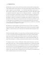
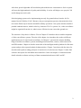
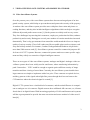
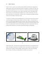
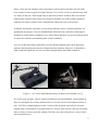
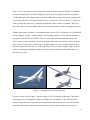
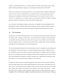
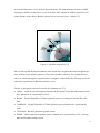
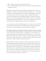
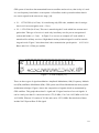
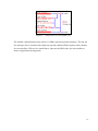
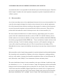
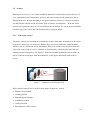
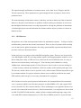
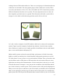
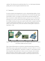
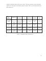
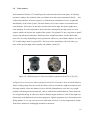
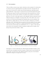
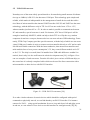
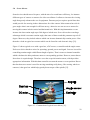
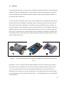
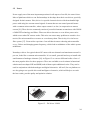
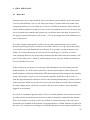
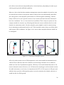
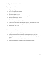
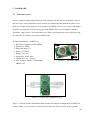
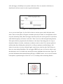
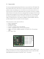
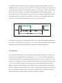
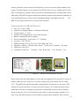
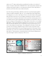
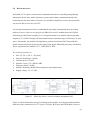
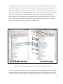
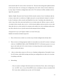
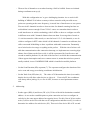
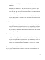
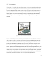
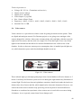
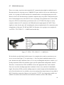
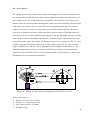
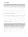
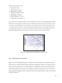
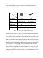
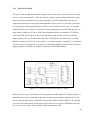
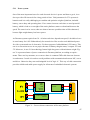
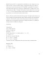
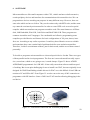
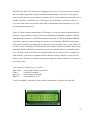
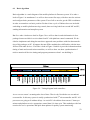
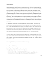
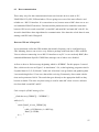
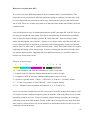
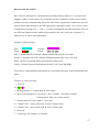
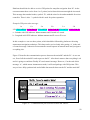

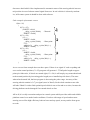
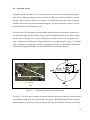
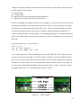
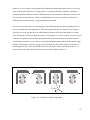
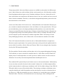
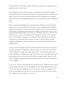
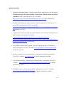
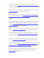
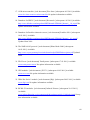
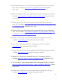
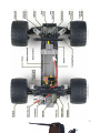


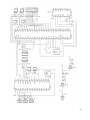
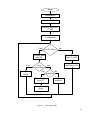
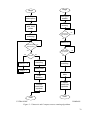
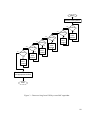
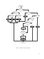
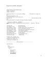
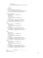
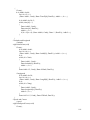

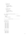
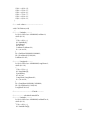
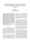
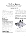
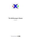
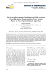
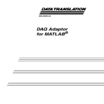
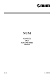

![COMBI DENTAIRE [J38COMBI] User Manual - Sport](http://vs1.manualzilla.com/store/data/006192000_1-b89c22e293354a4f6a722dcbfffb8846-150x150.png)
