1
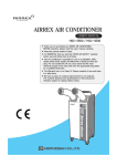
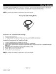
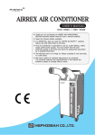
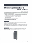
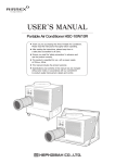
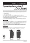
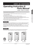
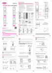
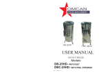
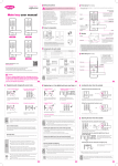
AIRREX DC HEATER
Operating Instruction &
Parts Manual
MODEL : AD-1250 / AD-2470 / AD-4890 / AD-7290
Please read and save these instructions. Read carefully before attempting to assemble, install, operate or
maintain the product described. Protect yourself and others by observing all safety information.
Failure to comply with instructions could result in personal injury and/or property damage!
Retain instructions for future reference.
▶ Thank you for purchasing an AIRREX DC HEATER. Before operation please read this
user's manual carefully.
▶ Keep this manual readily available.
▶ It is ESSENTIAL that you read it carefully before use, and follow it at all times.
▶ Please complete the warranty form now and keep in a safe place.
▶ We have a policy of continual improving to our products. The contents (features and specifications)
in this manual are therefore subject to change without notice.
rev0-2013
Contens
Cautions
3,4
Precautions Before Use
4
Main Features of Airrex DC Heater
5,6
Wiring Diagram
Specifications
6
7,8
Installation 9,10
Preparation & Operation
11,12
Self Diagnostic Codes
13
Maintenance & Parts
13
Warranty 14
2
rev0
Cautions
※Read this before using the product.
■ The instruction manual can be amended without prior notice.
■ Please read this instruction manual thoroughly before using the product.
■ Please learn the precautions for safety before using the product.
■ Please keep this manual around for using in the future.
Introduction
Danger
It means dangerous results such as serious injury or death can
be caused due to wrong use of equipment.
Warning
It means dangerous results such as serious injury or death can
be caused due to wrong use of equipment.
Caution
It means dangerous results such as minor injury or damage
to asset can be caused due to wrong use of equipment.
► Safety symbols as below are used throughout this manual.
►To maximize the performance of DC HEATER, read this product manual thoroughly.
Safety Instructions
Danger
■ Do not operate it at where there is a risk for explosion.
To avoid explosion, do not operate this product at where there is a risk for explosion. Or, it is necessary
to verify that it can be operated at the risky place.
Warning
When using the equipment, it is necessary to follow the items below.
1. Before connecting power supply, do not fail to check the polarity. (+ Red, - Black)
2. Install the equipment in the manner that duct and outlet are not blocked.
3. Do not block the fan or put any foreign matters while using it (To avoid the fan damage or overheating)
4. To protect the product, do not take out the installed fuse or replace it with other materials
(i.e. gum paper, aluminum foil, etc.)
5. Replace the fuse with the same capacity one, and make sure that it is firmly fixed. In addition, do never
take out the fuse after replacing it.
6. Avoid fuse heating and damage due to the loosened fuse terminal.
7. When connecting power supply to the main body, make sure that the connection is correct before using it.
(Loosened terminal can cause overheating or deteriorated performance of the product)
8. When using wires other than included, make sure to check the dimensions.
9. This equipment must be operated by the well-trained and skilled operators.
rev0
3
Cautions
Caution
1. This product works with the surplus power from the generator working in conjunction with vehicle engine,
so it can be normally operated during normal driving. When using it without starting the engine or
with low RPM of engine, the battery can be fully drained. With additional battery installed, it can be used
for a long track of time. (To protect the battery, the heater is stopped due to safety device when the voltage
decreases under certain voltage.)
2. This product is only for use as an auxiliary heater.
3. With the power supply cable extended, the performance of heater can be deteriorated.
Safety Precaution for Use
When using the equipment, it is necessary to follow the items below.
1. When using the device, it is always needed to observe the basic safety precautions as follows.
2. Before using the equipment, read all the instructions of user manual. Furthermore, store the manual
in the manner that it can be referred to whenever necessary.
3. This equipment must be operated by a well-trained and skilled operator.
4. Before using the equipment, check if the local safety regulations and standards are observed.
5. Do not use the equipment other than the intended purposes.
6. Electronic units must be maintained by the technically-qualified persons, or under the guide and
supervision of those persons.
7. For wiring, watch out for short (short circuit). (Danger for fire & vehicle damage)
8. Do not install and use the product other than the auxiliary heater.
9. Never attempt to disassemble, repair, or remodel the unit.
10. If the equipment is damaged due to the design change without prior notice from Hephzibah Co., Ltd,
we are not responsible for the damage.
11. General maintenance and inspection must be carried out only by a qualified person.
Precautions Before Use
1. Before connecting power supply, do not fail to check the positions for Red (+) and Black (-)
poles. If poles are connected in opposite ways, vehicle electrical system can be damaged.
2. Make sure that air intake or outlet of the heater is not blocked before starting the heater.
(When they are blocked, E3 error is displayed. It operates again when the internal temperature is decreased).
3. Do not block the fan or put any foreign matters while using it (To avoid the fan damage or overheating)
4. Replace the fuse with the same capacity one, and make sure that it is firmly fixed.
5. When connecting power supply to the main body, make sure that the connection is correct before using it.
4
rev0
Main Features of Airrex DC Heater
AV (Activity Variable) Heating Element
"AV Heating Element", which is applied to this product, is the world-first invented excellent heating element.
Heating value of "AV Heating Element" is variable according to the ambient temperature, so the heating value
can be actively changed with a range of 30% when opening or closing the doors. With a long-time usage,
the performance is not deteriorated, and it can be used for a long time. This is a very safe DC heating
element due to its low surface temperature.
Automatic Low Voltage Detection and Shut Down
This product automatically monitors the problems of all power supply lines for generator, condenser, and
power supply circuit so that the heater can normally operate. If any problem is detected, it cuts the power
automatically to prevent inabilities to start engine and to provide safety.
When abnormal condition is detected with the power supply, indicator (red color) is lit on the remote controller
and the power supply is cut if the condition is not solved within 3 seconds.
For safety, this product monitors power supply condition in real time. Thanks to the design of safety memory
circuit, when monitoring circuit cuts the power to heater, the heater is not restarted even if the circuit is
recovered. Therefore, before starting the heater again, it is necessary to delete all memories by pressing
OFF button of the remote controller for 2 seconds or longer and then press the Power button.
(For the safe and efficient use of product according to the usage environment, low-voltage limit is set in
2 modes. To change the basic value, refer to how to change the mode (See 6.4 for the details).
Temperature Setting
This product is designed to change the temperature by 1℉, from 32℉ to 104℉. From the remote controller,
press ▲ button on the left-side temperature adjustment part to increase the temperature and ▼ button to
decrease the temperature. When the ambient temperature reaches the setting temperature, power supply is
cut, and when the ambient decreases 2℉ from the setting temperature, power is supplied again so that
the temperature can be controlled with a high accuracy.
Overheating Prevention
To provide maximum safety, double-layered overheating protection is equipped with this product.
When the heater is covered or blocked, blower motor broken, or foreign matter interrupts the ventilation
causing overheating problems, the temperature sensor that is attached to the heating element will turn off
the power supply for safety.
SLOW STOP Function
When the use of heater is completed and the power supply is cut, latent heat of the heater is fully discharged
for safety. When the power supply is cut while the heater is operating, the blower motor slowly reduces its
speed to discharge the latent heat before stop the operation.
SLOW START Function
The heating element is warmed up gradually, according to the heating intensity increasing, the blower
motor's revolution is increasing. This is a fuction to prevent cold wind supply by increasing the motor speed
slowly according to the heating element warming up.
rev0
5
Main Features of Airrex DC Heater
Hot-Wind Direction Control
The outlet can be adjusted to left, right, up, and down as desired, and the outlet is closed when it is not used
for a long time so that inflow of dust or foreign materials can be avoided.
Highly-Sensitive Temperature Sensor
The included highly-sensitive sensor can change the detection range to 59 inch from the main body according
to the usage environment. So it can control the ambient temperature with a high accuracy.
Monitoring Function
When operating the heater, LCD display of the remote controller automatically shows voltage,
current temperature, temperature setting, and air volume, so that the user can understand
the current operation status at a glance.
Latching Relay
Latching relay is a high capacity component that can be used up to 100A input. General relay should have
a certain amount of electricity supplied, but this latching relay, of which electric supply is only used for 1 sec.
or less, and cut the supply. By doing this, it's much safer component than normal relay, and has high
durability of contact point.
Wiring Diagram
6
rev0
Specifications
DC HEATER Specifications
MODEL
AD-1250
AD-2470
AD-4890
Power Voltage
DC 12V
DC 24V
DC 48V
Power Consumption
500W
700W
900W
Dimensions (WxDxH)
270 X 220 X 115mm (10.9 X 8.3 X 4.5 inch)
Weight
1.9kg
AD-7290
DC 72/80V
900W
2.0kg
DC HEATER Component
Main Body
Screws
Controller
Manual
Mounting Plate
rev0
Main Power Cable
7
Specifications
Assembly Drawing
Parts List
No.
Parts name
1 Temperature Sensor
2 Controller Connection Wire
3
Upper Case
4
Inlet Filter (RH)
5
Impeller(RH)
6
Motor
7
Impeller(LH)
8
No.
Parts name
No.
Parts name
8
Inlet Dust Filter (LH)
15
AV Heater Element Ass'y
9
10
11
12
13
14
Wind Guard (RH)
PCB Ass'y (RELAY)
Wind Guard (LH)
Grommet (UPPER)
Grommet (LOWER)
Wind Protector
16
17
18
19
20
Heater Cover
Bottom Case
Mounting Plate
Main Power Cable
Remote Controller
rev0
Installation
※In this section, it describes how to install and use the heater
and the remote controller.
How to install the Airrex DC heater is different according to the type of vehicle, installation type and
installation location. In addition, DC generator and battery specifications make a difference in the product
specifications and how to install. This manual only describes how to install the heater on a general type
vehicle. Full attention is required during the installation.
Main Body Installation, Power Connection, and Cautions
►When installing main body of the heater, mount the body with bolts or use mounting bracket according to
the installation conditions. Accordingly, measure the distance between battery and fuse box for wiring,
and decide where to install the controller an d wiring.
► When connecting the main power supply, check the locations and colors of (+) and (-) poles for
correct installations.
►The customer is solely responsible for damage caused by negligent connections.
► To avoid dangerous results due to incorrect connections, connect the wire correctly.
Do not use the main body as a step board or a support place for other components.
Mounting Plate Specifications
Ø
Ø
Dimensions (inch)
rev0
9
Installation
Warning
■ Do not use it while the wires are not firmly connected to the battery terminal.
■ Contact failure can cause spark (electric spark) resulting in explosion and engine start failure.
Caution
■ When connecting the power cable, check the polarities. (+ Red, - Black)
■ Open the outlet and energize the equipment to use.
■ Do not put any foreign matters in the outlet or left & right intakes.
Installation
Before installation, check the power cables and fuses.
Turn the car key to OFF position
Black(-)
Check the power voltage specifications for the model
and connect it with battery.
Red(+)
Red(+)
Black(-)
►When connecting the wire to battery, check
the positions for Red (+) and Black (-) poles.
►If poles are connected in opposite ways, vehicle
electrical system can be damaged.
10
rev0
Preparation & Operation
Controller
①
②
③
⑤
⑥
④
⑦
⑧
1. Temperature Display
Number in the display ① is the ambient temperature.
2. Setting Temperature
Number in the display ② is the setting temperature.
3. Voltage Display
Number in the display ⑤ is the battery voltage.
4. Wind Volume Display
In the display ③, indicator is lit on from step 1 to 4,
to show the wind volume state.
5. Wind Volume Control
When pressing ▲ button ④ located on the right side of
wind volume controls, the volume is increased and
▼ button is used to decrease the volume.
6. Power Button (ON/OFF)
By pressing ON/OFF button of display ⑧ for 2 seconds
or more, main body can be activated or deactivated.
7. Temperature Control Button
By pressing ▲ button of the display ⑦, temperature
setting can be increased up to 104℉ (Holding the button
pressed increases the setting continuously).
By pressing ▼ button, temperature setting can be
decreased to 1℉. (Holding the button pressed decreases
the setting continuously).
8. Low-voltage Indicator
When the battery of display ⑥ is not sufficiently charged to
operate the equipment, warning indicator is on and
the heater is stopped.
Low-voltage Warning Setting Value
MODE
DC12V DC24V HOW TO CHANGE MODE
1
2
Others
10.5V 21.0V
9.5V 19.0V
By pressing Up and Down
buttons of wind volume control
for 5 seconds, the standard value
of the current voltage display
blinks 3 times and sets.
* For low-voltage indicator, lower limit can be changed for
the low voltage according to the usage environment
(The default mode is MODE 1)
* With the same changing method, mode can be changed.
* When batteries are removed from the remote controller,
all the functions are returned to the defaults, so it will be
necessary to set the values again as desired.
■ When the battery power is not enough, the low-voltage warning indicator (red color) is lit on the controller.
■ If the power is not recovered even after the low-voltage warning, the controller automatically stops
the heater operation.
■ To use the heater after low-voltage warning, the battery needs to be charged.
rev0
11
Preparation & Operation
Preparations for Operation
►Mount the main body and make sure that the wiring is correct.
►Make sure that wiring is firmly fixed.
►Make sure that the main body and controller is firmly fixed
Operation Condition
This product is a heater warming up the indoor air. The efficiency is affected by the inflowing outside air,
insulation, and space size.
This product is a heater using battery power. So the usage time of products varies according to the car battery status.
Operation
Power
Press ON/OFF button located in the center of the remote controller
for 2 seconds to open or close the power with electrical sound.
Temperature Control
Use Up and Down buttons on the left side of the temperature
control buttons and the temperature setting is displayed on
the upper-right corner of the remote controller
(Press the button continuously to control it continuously).
If you want to change temperature unit ℉ ↔ ℃, push ▼
and ▲ button (temperature control buttons) simultaneously
for 5 sec.
Remote Controller Display
On the display, current air temperature (upper left) and battery
voltage (bottom left) are displayed.
Use Temperature Control button (Up/Down) to increase or
decrease the temperature. When ambient temperature reaches
the setting temperature, heater stops. It works until the ambient
temperature reaches the setting temperature. Additionally,
when surplus power is drained from the battery, the built-in
low-voltage cutoff automatically cut the power.
(When the equipment doesn't work due to low voltage, charge
the battery sufficiently so that the equipment works.)
Current temperature and battery voltage are shown on
the upper left of the display, and temperature setting is shown on
the bottom left of the display.
Wind Volume Control
With Up/Down buttons for wind volume, wind volume
can be controlled.
12
rev0
Self Diagnostic Codes
The Alarm light is activated if abnormal operation occurs, and an error code is displayed on the control panel.
In this case, the compressor will stop operating.
Error Code
Problem
Cause Corrective Action
Sensor Problem
Temper Sensor Open
Changed Temperature Sensor
Sensor Problem
Thermistor(J7) short-circuit
Changed Thermistor
Bimetal Sensor
Problem
·Measure taken for normal
·Abnormal temperature
increase of heating element. operation of motor
·Removing the cause of
·Motor failure
·Blocked air intake and outlet problem at the intake
& outlet
Maintenance & Parts
※In this section, it describes what measures
have to be taken when the system doesn't
work in normal way.
Check List
►Check wiring and fuse short
(Check + and - poles, process status of power and ground terminals, and no-loosed fixings)
►Check battery capacity & generator capacity
(Check the battery and generator capacity of the vehicle, to decide the capacity of heater to be installed)
►Select the heater according to the usage
(Select heater capacity according to the usage conditions of consumers)
►Mak▲e sure that air intake or outlet of the heater is not blocked before starting the heater.
(When they are blocked, E3 error is displayed. It operates again when the internal temperature is decreased).
* Most problems are caused by the usage conditions. * Make sure that air intake and outlet are not blocked.
* For wiring, connect +(Red) and -(Black) at the correct positions.
rev0
13
Warranty
AIRREX DC HEATER is more reliable, comfortable, and durable the more they are
used. They are built under a strict quality guidelines which includes
inspection both during and after production and reliability testing.
In the unlikely event you have any problems, please contact your dealer or
distributor. If the problem is as a result of a production fault or failure, repairs will
be free of charge during the period of warranty subject to the following warranty
conditions:
1. If the problem has been caused by customer error or misuse, abuse or
damage, then all repairs will be charged for.
2. This warranty applies to your country.
3. Proof and date of purchase must be supplied.
4. Please complete the details below and keep this warranty in a safe place.
5. All transport charges back to the dealer are at the customers cost. Keep all
original packaging to facilitate return. Return to customer will be at dealers cost
(if genuine warranty claim).
DESCRIPTION
AIRREX DC HEATER
MODEL
AD-1250 / AD-2470 / AD-4890 / AD-7290
DATE OF PURCHASE
PRODUCT
SERIAL NO:
Months
WARRANTY PERIOD
DISTRIBUTOR
Name of Company
Telephone No.
Name :
CUSTOMER
DETAILS
Address :
Telephone :
14
rev0
MEMO.
rev0
15
Manufactured by :
HEPHZIBAH CO.,LTD.
(Juan-dong) 86, Gilpa-ro
71beon-gil, Nam-gu,
Incheon, Korea
TEL : +82-32-509-5834
FAX : +82-32-502-5519
E-mail : [email protected]
Website : www.airrex.biz
● Designs and specifications of products are subject to change without prior notice for the improvement of products.