1
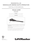
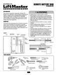
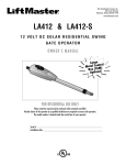
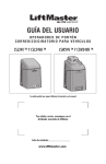
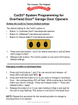
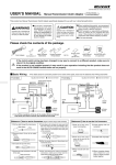
REMOTE BATTERY BOX
WARNING
®
OOKSON
WARNING50-BATBOX-FDO
Rolling Doors
CAUTION
WARNING
To reduce the risk of SEVERE INJURY or DEATH:
• ANY maintenance to the operator or in the area near the
operator MUST NOT be performed until disconnecting the
electrical power and locking out the power via the operator
power switch. Upon completion of maintenance, the area
MUST be cleared and secured. At that time the unit may be
returned to service.
• ALL electrical connections MUST be made by a qualified
individual.
• DO NOT install ANY wiring or attempt to run the operator
without consulting the wiring diagram.
• ALL power and control wiring MUST be run in separate
conduit.
• The Remote Battery Box MUST be mounted on the same
side of the firedoor that the Operator is mounted to.
• The sealed lead-acid batteries in the Remote Battery Box
contain materials that are harmful to personnel and to the
environment. DO NOT handle or utilize batteries that are
damaged in ANY way. RECYCLE or DISPOSE of old or
damaged batteries within the guidelines established by
LOCAL LAW.
APPLICATION
This accessory is intended for Cookson FDO operators only.
Additionally, it will be necessary to ensure that the FDO operator
is equipped with the CHARGING CIRCUIT BOARD. To determine if
the FDO operator is equipped with this CHARGING CIRCUIT
BOARD, refer to the FDO operator user’s manual, or call the
service department for additional information and how to order
charging circuit board upgrade kits.
FUNCTION
The function of the remote battery box is to provide a convenient
means to house the batteries for the operator at a separate,
nearby location. This accessory provides the flexibility to install
the operator above a drop ceiling or other difficult to access
location, retaining access to perform routine maintenance on the
battery power source for the operator.
FIGURE 1
Cover
Battery
Bracket
Battery Bracket
Retaining Nut
Terminal
Block
Remote Battery
Box Enclosure
Flexible Conduit
Conduit Connector
Black Battery
Harness (-)
Red Conduit Wire
Black Conduit Wire
Green Conduit Wire
Red Operator Harness (+)
Red Battery
Harness (+)
Black Operator Harness (-)
Fuse Assembly
Tie
Wraps
Grounding Screw
and Washer
TOOLS NEEDED
Pencil
Philips Head Screwdriver
Pliers
Drill
Adjustable End Wrench
Drill Bits
3/16", 5/16"
and 5/32"
Flathead Screwdriver
Wire Crimpers
Wire Cutters & Strippers
Hammer
Torque Screwdriver
1
Sockets and Wrench
1/2", 5/8", 7/16", 9/16"
and 1/4"
INSTALLATION
BATTERY BOX MOUNTING
To mount the conduit to the wall, utilize UL recognized conduit
clamps and supports intended for 3/8" flexible conduit. Secure to
the surface with recommended the hardware.
1. Determine the location for mounting the Remote Battery Box.
NOTE: The remote battery box MUST be mounted on the
same side of the firewall as the operator and MUST be less
than eight feet from the operator.
2. Select the proper hardware to be used for mounting based on
application in accordance with local regulations. Refer to the
recommended hardware for mounting the battery box on
various surfaces as a guide.
3. Position the enclosure at its desired location. Mark the
mounting holes of the enclosure on the intended surface.
Refer to mounting hole dimensions (Figure 2).
4. Mount enclosure using hardware.
NOTE: The battery box MUST be mounted in an upright
position; otherwise premature battery failure may result.
SURFACE
RECOMMENDED FASTENERS
Dry Wall
Utilize hollow wall anchors, molly bolts
or toggle bolts that will secure a 3/16"
screw, unless securing into a stud.
Ensure that the fastener is rated for the
thickness of the sheet rock.
Use a 3/16" wood screw with enough
length to secure.
Use a concrete anchor of at least 2" that
will mount a 3/16" screw.
Wood (studs)
Brick,
Concrete Block,
Cement
FIGURE 2
7-5/8"
8-11/16"
CONDUIT WIRING
1. Disconnect power to operator.
2. Remove the cover to the operator and disconnect the battery
power connector.
3. Open the battery box by removing the two screws.
4. Route the flexible conduit between the battery box and the
operator. Remove the desired knock-outs on the operator and
the battery box.
5. Secure the flexible conduit to the removed knock-outs on both
the operator and the battery box using conduit connectors.
6. Secure the conduit to the wall.
7. Connect one end of the conduit provided to the desired
knockout on the Remote Battery Box and make connections
as follows (Figure 3):
a. Connect the green conduit wire to the grounding screw and
washer.
b. Connect the red conduit wire to TB2-5.
c. Connect the black conduit wire to TB2-6.
8. Connect the other end of the conduit provided to the desired
position on the FDO Operator and make connections as
follows (Figure 4):
d. Connect the green conduit wire to the ground screw located
in the operator’s electrical box.
e. Connect the red conduit wire to TB1-3.
f. Connect the black conduit wire to TB1-4.
NOTE: Do not exceed 16 in/lbs when tightening the terminal
block screws.
Black
Battery
Harness (-)
Black Conduit Wire
Red
Battery
Harness (+)
Red Conduit Wire
Green Conduit Wire
FIGURE 3
Grounding Screw and Washer
Black Operator Harness (-)
Red Operator
Harness (+) 1
2
5
6
7
8
*Pre-existing connections
to terminal block not shown
for clarification*
9 10
Red Conduit Wire
Black Conduit Wire
FIGURE 4
2
CONNECTION DIAGRAM (FDO)
BATTERY BOX
CONNECTIONS
CONTROL BOX CONNECTIONS
MAIN BOARD
#J14
SPLICE
OPERATOR
BLOCK (TB1)
BK
BATT #1
BATT #2
BK
BK
BK
FUSE
BK
BK
NEW WIRES
BATTERY
BOARD
J6
J1
J2
RD
RD
J7 J3 J4
J5
BATTERY
BLOCK (TB2)
RD
GN
SPLICE
RD
OPERATOR
GROUND
GROUND
CONDUIT
WIRES
RATING INFORMATION
SERVICE PARTS
BATTERY (1): K29-NP712
FUSE: 35-313-005
BATTERY BOX ASSEMBLY: 50-BATBOX-FDO
BATTERY: NOMINAL VOLTAGE 12VDC
FUSE: 5 Amp, 250V, Type 3AG
WARNING: FOR CONTINUED PROTECTION
AGAINST FIRE, REPLACE ONLY WITH THE
SAME TYPE AND RATING OF FUSE.
40-33380B
OPERATOR WIRING
1. Gain access to the operator’s batteries and identify;
a. Jumper wire connected between the batteries.
b. The red wire connected to one of the battery’s positive
terminal.
c. The black wire connected to the negative side of a battery.
2. Disconnect and discard the jumper between the batteries.
3. Disconnect the red and black wires from the battery terminals.
4. Remove the batteries from the operator and retain.
NOTE: If the battery box is being placed into a new
installation, use the existing batteries from the FDO Operator.
If adding the battery box to an existing installation, new
batteries will be required, and the old batteries MUST be
removed from the operator.
5. Using wire cutters, cut off the 3/16" battery connectors from
the red and black wires noted in step 1, making the cut as
close to the connectors as possible.
6. Strip 3/8" of the insulation from the red and black wires.
7. Remove the red operator harness (+) from the parts bag.
8. Crimp the butt splice side of the red operator harness to the
red battery wire of the operator that was prepared above using
the approved crimping tool.
9. Route the fork connector of the red operator harness to TB1-3
(Figure 4).
10.Remove the black operator harness from the parts bag.
11.Crimp the butt splice side of the black operator harness (-) to
the black battery wire of the operator that was prepared above
using the approved crimping tool.
12.Route the fork connector of the black operator harness to
TB1-4 (Figure 4).
NOTE: Do not exceed 16 in/lbs when tightening the terminal
block screws.
13.Tie wrap the added wires along existing harnesses in the
operator. Replace all hardware removed while gaining access
to the batteries in step 1. Do not replace the cover at this time.
NOTE: Do not connect battery connector or apply AC power to
the operator until installation of battery box is complete.
3
BATTERY INSTALLATION
BATTERY REPLACEMENT
1. Remove the retaining nut securing the battery bracket to the
enclosure and retain.
2. Remove the bracket from the enclosure.
NOTE: Be careful not to remove any preinstalled wires.
3. Slide the two batteries into the enclosure. Ensure that the
batteries are mounted UPRIGHT.
4. Connect the wires of the fuse between (+) of battery #1 and
(-) of battery #2.
5. Connect the free end of the pre-wired black battery harness
located on TB2-6 to the negative (-) terminal of battery #1.
6. Connect the free end of the pre-wired red battery harness
located on TB2-5 to the positive (+) terminal of battery #2.
7. Secure the batteries into the box by reinstalling the battery
bracket with the bracket retaining nut in the same manner in
which it was removed.
8. Close the box and secure the lid with the two screws.
1. Disconnect power to operator.
2. Remove the cover to the operator and disconnect the battery
power connector.
3. Open the battery box by removing the two screws.
4. Remove retaining nut securing the battery bracket and set
bracket aside.
5. Remove the connections on the battery terminals and set fuse
aside.
6. Remove the old batteries from the enclosure and dispose of
them in accordance to local regulations.
7. Slide two new batteries into the enclosure and connect the
fuse between (+) of battery #1 and (-) of battery #2.
8. Connect the end of the black battery harness (-) from TB1-6
to (-) of battery #1.
9. Connect the end of the red battery harness (+) from TB1-5 to
(+) of battery #2.
10.Secure the batteries into the box by reinstalling the battery
bracket and retaining nut.
11.Close the battery box and secure the cover.
12.Reconnect the battery power connector in the operator and
replace the cover.
13.Connect power to the operator.
TESTING AND MAINTENANCE
CONNECT POWER AND TEST
1. Apply power to operator and connect battery power connector
within the operator.
2. If required, re-program unit using installation instructions
provided with the operator.
3. Test Unit
a. Pull the red wire off J13 of the logic board and meter for
27.3 – 27.8 Vdc versus terminal #15 of the logic board.
Reconnect the red wire on J13 of the logic board.
b. Conduct a battery load test by making contact from
terminal #6 to #7 of the logic board six times within ten
seconds (Key Test).
c. Meter again between the red wire from J13 and terminal
#15 of the logic board for a voltage dropping from the
reading taken in step a. An example might be 27.5Vdc was
read in step a, and a slow but steady decline from 27.5
Vdc is observed under load.
4. Replace the operator’s cover.
HOW TO ORDER REPAIR PARTS
OUR LARGE SERVICE ORGANIZATION
SPANS AMERICA
Installation and service information are available.
Call our TOLL FREE number:
1-800-294-4358
www.cooksondoor.com
www.liftmaster.com
01-33389B
©2006, The Chamberlain Group, Inc.
All Rights Reserved