1
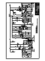
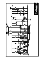
Compex F760X-RS
By
Compex F760X-RS
by
AUDIO & DESIGN (READING) LTD.
with Q2 Audio, LLC
Communication Bulletin No. 103
14th January, ‘13
(original: 9th June, ‘74)
Initial Unpacking and Set-up
After carefully removing your Compex from it’s shipping box, save the packaging for a few days to be sure you do not
need to return the unit for any reason. If necessary please return it using the original box and packing materials. Before
applying mains power check that the power transformer is properly configured for your mains voltage by checking the
small window visible on the fuse drawer of the IEC mains connector. When the drawer is removed (use a straight bladed
screw driver) a small PCB can be seen which will slide out and it can be flipped over to select the proper mains voltage
for your area. There are two settings, one marked “110V” which is for operation at 110V to 120V and one marked “240V”
which is for operation at 220V to 240V. Fuse ratings for specific mains voltages are screened on the back of the Compex.
If there are any questions, please contact Q2 Audio directly via the contact info at: www.q2audio.com. There are no user
serviceable parts inside the Compex, please contact your dealer or Q2 Audio for servicing. Unauthorized third party servicing will void the warranty.
Audio XLR I/O wiring:
The audio is connected via standard 3-pin XLR. Inputs and outputs are unbalanced unless ordered with the transformer
option. The pinout is as follows:
Pin 1: Chassis
Pin 2: Audio +
Pin 3: 0V (Audio -)
If problems such as hum, etc., are encountered there are a couple of possible routes to eliminating this: 1) lift shield at
Pin 1 of input audio wiring. This is easiest to accomplish in the XLR connector on the end of your wiring. If that does not
fix the problem, lifting pin 3 at the input may be the next choice. This same sequence can be followed on the output XLR.
Interfacing unbalanced equipment can be a challenge in certain instances.
Side Chain Insert TRS wiring:
Both the compression and expander/gate side chains can be accessed via the TRS on the rear panel (factory default is
compression). The TRS jack is of the switching type so it can be permanently wired to a patchbay although it is possible
that this could lead to noise pickup in electrically noisy environments.
The pinout of the TRS jack is as follows:
Tip: Return
Ring: Send
Sleeve: 0V (shield)
If you wish to use switch the side chain access TRS jack to allow access to the expander/gate for ducking or similar effects, REMOVE/ISOLATE FROM MAINS POWER FIRST! Once mains power is removed,removing the top cover and
move the insert wire from the main PCB to the front panel PCB. On the front panel PCB you will find a three pin header
with a shorting jumper on it. The jumper needs to be removed and the insert wiring needs to be moved from the main PCB
and installed on the three pin header on the front panel PCB. The jumper that was removed from the front PCB needs to
be installed on the main PCB in place of the insert wiring that was removed – install between “go” and “return” so those
two points are shorted together (without the jumper the compression will not work).
Further information available @ www.q2audio.com
F760X Series Limiter - Compressor-Expander
Operation Procedure: Quick Start
Establishing the unit in the channel
***Verify proper mains voltage setting before applying power***
a). Check Expander section switched ‘out’; Compressor Ratio switched to 1:1 (i.e. non-operative); the Peak Limit switched ‘In’; and the output attenuator turned down (in a stereo unit the individual channel potentiometers would be fully open
on each channel with control effected on the ganged device) would be adjusted as required.
b). With the channel by-pass switch to ‘out’ (i.e. by-passing the F760 Compressor amp section) the channel levels should be established in the usual way as though the F760 were not in circuit. The channel level should be peaking to at least -10dBm, but preferably to 0dBm in order to obtain maximum compression possibilities.
c). Having established the normal level, switch the F760 ‘In’ and adjust the Input pot until the overall amount of gain reduction likely to be required, is indicating on the meter (e.g. 10dB). At this stage the Peak Limit section is working and red
indicator will be flashing.
d). Open the Output attenuator and adjust so that the level is peaking to the same level as the direct signal. This is best done under dynamic signal conditions rather than on tone if monitoring with VU meters (see LIMITING & COMPRES
SION – Considerations). A relevant direct comparison is now available between direct and compressed signal at the flick of the ‘In/Out’ switch at closely approximating peak levels.
e). With the compressor Ratio control select the Slope required (e.g. 2:1) and adjust the Compressor Threshold control
until the Peak Limit only indicates on peaks above the amount of compression required (i.e. move the threshold down
from ‘0’ towards the -20 point until the Limit light goes out, then come back one position). The limit section will then operate on any further unexpected increase in level. The amount of compression may be changed by increasing/decreasing
the Input pot and adjusting the Compressr Threshold adjust the realtionship between compression and peak limiting.
Once set-up it will not be necessary to alter the Output level (as per step ‘d’).
f). The Release time in the compressor section will be adjusted for effect and the Attack time. Note when long Attack time
is selected more peak limiting will occur.
g). In adjusting the compressor section always reference it to the Peak Limiter even if the Pk.Limit is then switched out
during operation. This maintains the optimum signal-noise level in the system. When using the tighter slopes in the compressor the Threshold will lie just under the Pk.Limit in position -2 to -8 (20:1 to 3:1 ratios).
h). The Compression Slopes are calculated on a 15dB range of gain reduction. (i.e. the 2:1 ratio is established in the
set-up procedure as 30:15). It will be found in practice that the initial slope in that position is more akin to 1:1.5 becoming
slightly tigher as gain reduction increases. Thus if only 6dB of compression were required this will be softer than the ratio
indicated and the next position higher could be selected. In practice this will not be found of great importance but it is useful to know of.
Further information available @ www.q2audio.com
OPERATION PROCEDURE
Establishing the unit in the channel
a). Check Expander section switched ‘out’; Compressor Ratio switched to 1:1 (i.e. non-operative); the Peak Limit switched
‘In’; and the output attenuator turned down (in a stereo unit the individual channel potentiometers would be fully open on
each channel with control effected on the ganged device) would be adjusted as required.
b). With the channel by-pass switch to ‘out’ (i.e. by-passing the F760 Compressor amp section) the channel levels should
be established in the usual way as though the F760 were not in circuit. The channel level should be peaking to at least
-10dBm, but preferably to 0dBm in order to obtain maximum compression possibilities.
c). Having established the normal level, switch the F760 ‘In’ and adjust the Input pot until the overall amount of gain reduction likely to be required, is indicating on the meter (e.g. 10dB). At this stage the Peak Limit section is working and red
indicator will be flashing.
d). Open the Output attenuator and adjust so that the level is peaking to the same level as the direct signal. This is best
done under dynamic signal conditions rather than on tone if monitoring with VU meters (see LIMITING & COMPRESSION
– Considerations). A relevant direct comparison is now available between direct and compressed signal at the flick of the
‘In/Out’ switch at closely approximating peak levels.
e). With the compressor Ratio control select the Slope required (e.g. 2:1) and adjust the Compressor Threshold control
until the Peak Limit only indicates on peaks above the amount of compression required (i.e. move the threshold down
from ‘0’ towards the -20 point until the Limit light goes out, then come back one position). The limit section will then operate on any further unexpected increase in level. The amount of compression may be changed by increasing/decreasing
the Input pot and adjusting the Compressor Threshold adjust the relationship between compression and peak limiting.
Once set-up it will not be necessary to alter the Output level (as per step ‘d’).
f). The Release time in the compressor section will be adjusted for effect and the Attack time. Note when long Attack time
is selected more peak limiting will occur.
g). In adjusting the compressor section always reference it to the Peak Limiter even if the Pk.Limit is then switched out
during operation. This maintains the optimum signal-noise level in the system. When using the tighter slopes in the compressor the Threshold will lie just under the Pk.Limit in position -2 to -8 (20:1 to 3:1 ratios).
h). The Compression Slopes are calculated on a 15dB range of gain reduction. (i.e. the 2:1 ratio is established in the
set-up procedure as 30:15). It will be found in practice that the initial slope in that position is more akin to 1:1.5 becoming
slightly tighter as gain reduction increases. Thus if only 6dB of compression were required this will be softer than the ratio
indicated and the next position higher could be selected. In practice this will not be found of great importance but it is useful to know of.
The Expander/Gate Section: Expand Mode
i). in the ‘Expand’ mode the low level gain reduction slope is of the order of 2:1. The control is ‘feed forward’ so that the
expander side-chain is arranged to monitor the input signal prior to the F760 input attenuators. The meter will indicate gain
reduction when it operates and at the same time the green indicator will flash to differentiate it from high level gain reduction (limiting/compression).
j.) To set up the Expander mode it is probably best to switch the compressor section to 1:1 and back off the main input attenuator until Pk. Limiting it only just operating.
k). Switch the Expand/Gate switch to ‘Expand” and the Expand Attack to ‘M’. With the Expander Threshold fully anti-clockwise (shut – i.e. infinitely high) adjust the Expander Range control so that the maximum amount of low level attenuation is
set-up on the meter (i.e. 20dB) and the green indicator will be on.
l). Now open the Threshold control until the meter and light indicate no gain reduction when signal is present but with fast
expander Release attenuates quickly on unwanted noise/crosstalk. Thus the threshold is adjusted so that it is just open to
allow all wanted signal through, but is closing rapidly during pauses. If it is operating on noise and crosstalk there will be
no modulation effect and fastest release (attenuate time) can be sued (see Expander/Gate – Considerations). The open
speed will be determined by the Attack control switch.
m). Should the maximum attenuation range not be reached during pauses, this will be because the expander is being held
open to some degree on input noise (see Expander/Gate – Considerations). One must either accept the limited range
possible or turn back the threshold pot slightly so some of the wanted signal may now begin to be expanded; release and
attack may need adjustment to avoid modulation effects. The alternative is to use the GATE position.
n). Having established the Expander mode satisfactorily switch it ‘out’ re-establish the compression section by selecting
the ratio and increasing the input attenuator to give compression required. Then switch the Expand mode to ‘In’. Make any
final fine adjustments.
The Expander/Gate Section: GATE MODE
o). the Gate position provides low level gain reduction at a slope of 20:1. IN thie mode the control side-chain in in a ‘feedback’ arrangement deriving its sense-data frm the F760 output. Thus the Compressor/limiter sections myst be established
and fully operating whilst the Gate Threshold if found.
p). Having set up the Compressor/Limiter sections switch the F760bypass ‘In/Out’ switch to ‘Out’ so that no signal is going
through the unit.
q). Switch the Expander/Gate switch to the Gate mode. The green light will come on and the meter indicate gain reduction
providing the Range control is not on ‘0’. Adjust the Range control for the maximum amount of low level gain reduction
required ( i.e. -20 or whatever).
r). Switch in the F760 and adjust the Threshold of the Gate along with the Release and Attack controls so that it is closing
quickly on noise, yet fully open in the presence of wanted signal. (see EXPANDER/GATE - Considerations)
STEREO OPERATION
s). The Compressor section and Expander/Gate section are matched for stereo in stereo units. The ‘Stereo-Link’ switch
links the relative control voltages so that gain reduction is always identical on both channels thus obviating and image
shift. For simplicity it is best to set-up controls identically on both channels – setting each channel prior to throwing the
Stereo switch ‘IN’.
t.) The Peak Limit sections are not linked and will continue to function independently; momentary attenuation of transients
will not be appreciably noticeable with regard to image shift.
LIMITING & COMPRESSION – Considerations
The usual purpose of Limiting and Compression is to a). Increase loudness and b). to provide overload protection and
generally control level.
LIMITING implies the use of a level control divide to provide overload protection; its purpose to ‘limit’ the signal level at
some specified point. Transients are the major concern (that is peaks of a short duration) tghat exceed the pre-determined
peak recording level. Control of these will not markedly affect the dynamic range of the input signal since gain reduction
with it does occur, will be momentary and of a relatively low order of magnitude. In most cases a fast release time will be
desired so that transients are punched down without apparently affecting the programme content. A tight compression
ratio greater than 10:1 wold be used.
Such an action enables the engineer to reduce his system ‘headroom’, operate with a higher recording level without fear
of overload. The dynamic range or a recording or transmission system is thus increased.
COMPRESSION is used to describe conditions of rain reduction that are more or less continuous; thus the original dynamics are compressed. The compression ratio selected may be anything from the softest slope (say 2:1) to the tightest
(say 20:1) dependent on the effect desired.
When it is desirable to preserve some sensible relationship to the original dynamics, ratios of 2:1 or 3:1 would be used.
There is some significant increase at the output as the input rises on these slopes. 5:1 to 20:1 are tighter and the output
will not rise by much whatever the input level.
The diagram of the F760 slopes show this clearly; 15dB compression on a slope of 10:1 wold occur on the top 16.5dB
of the signal; the same amount effected at 2:1 is spread and affects the top 30dB of the signal. The 2:1 ratio is therefore
more subtle and the effect of fast release times less apparent.
The advantage of the F760 series over a straight Compressor-Limiter is that the softer slopes can be used to provide
subtle compression combined with overload protection at the top. It is thus safe to use the soft slopes’ and one does not
have to compromise by using a tighter slope that one would ideally like.
RELEASE-TIME is important in compression since it determines the moment to moment gain change in the system’ and it
is the rate of gain-change that determines loudness. The faster the release and the tighter the slope the more lower level
signal is brought up toward peak level. The problem introduced is that of ‘pumping’ or ‘breathing’ plus the effect of fast
release times on low frequency distortion. With very fast release the low frequency wave forms are being flattened’ this is
naturally most noticeable under conditions of considerable gain reduction coupled with a tight slope and fast attack time.
In practice it is surprising what one can get away with in ‘pop’ applications where these sort of extreme conditions can be
useful. With ‘serious’ programme material slower times will be used. The automatic programme controlled release position
‘A’ produces for a fast release over a range of 5dB whereupon it becomes long. Thus short duration gain change is limited
to a small amount obviating most of the problems described. It can be adjusted to operate as a ‘mean level’ control such
that the quieter sections are subtly lifted. Considerable overall compression can be effected without being apparent, and is
ideal for background music ore reducing dynamics for mediums of very limited dynamic range ( e.g. AM transmissions and
optical track etc.).
ATTACK TIME will determine the size of the transients allowed to pass through the compressor section (to be handled by
the Peak Limit section in a F760). In a limiter this shojld be very fast in order to control high frequency spikes and prevent
overloading. Some mediums are more critical than others; on tape it may be preferable to let the fastest through to saturate and be clipped in the tape itself’ with optical systems and transmitters it is usually essential to keep overshoot to the
absolute minimum.
In a compressor or limiter the slowing down of the attack time has the effect (dynamically speaking) of reducing the static
ratio, increasingly overshooting. Listening to 15dB compression on a 20:1 slope with a fast attack time, the tightness will
be quite apparent in the sound and this can be softened by reducing the attack time.
COMPRESSION & NOISE: From the point of view of minimal noise, it is preferable for the compression to be effected
on direct microphone signal since the signal-to-noise ratio is better at this stage (this is true if recording to tape, less so if
recording to modern professional digital audio mediums). It will be appreciated that 15dB compression will increase the
source noise by 15dBwhen the compressor fully recovers; off tape this would be more noticeable.
The use of the Expander or Gate section (where fitted) will obviate this when correctly set up.
MODULATION: If more than about 6dB of compression is used it is desirable to treat individual instruments or groups of
instruments, separately in order to avoid modulation effects when a dominant instrument or sound modulates the rest of
the signal. It is impossible to limit satisfactorily low frequency instruments on a final balance. Try limiting the low frequency
section of an organ recording or well modulated tympani in an orchestral recording; the effect on the remaining signal and
particularly the change in ambience is most apparent. By separately compressing groups of similar instruments considerable compression may be effected on direct signal without difficulty.
The F760X-RS re-issue has been fitted with a compression side-chain insert to allow an EQ to be inserted at the input to
the side-chain. A common use would be to reduce the low frequencies reaching the side-chain to greatly reduce modulation due to low frequency content.
EXPANDER-GATE – Considerations
The diagram of slopes attached indicates the difference between Expansion and Gate action. The Gate will attenuate its
full range for a very small change in input level at the threshold point; whilst the 2:1 expansion slope needs a greater input
change to effect a comparable amount of low level attenuation.
The Expander section with its 2:1 slope needs a change of 10dBat the input (below threshold) to obtain a 20dB attenuation range. The Gate section is 20:1 and theoretically needs only a change of 1dB below threshold for full 20dB attenuation.
The most common use for both systems is that of eliminating unwanted noise during pauses in programme signal; used in
the manner the threshold will normally be set just under the wanted signal level.
The Expansion slope being softer, is less critical to set-up and easier to use provided the signal-to-noise level is reasonable in the first place. If one is to avoid actually expanding some of the low level signal, the noise must lie 10dB below the
wanted signal at least, in order to get a further 10dB improvement. If it’s only 5dB below the expander can only improve
it by a further 5dB where it is then held open by the noise itself. In that case the threshold can be lifted so that part of
the lower level signal is being expanded, but there is then the danger of modulation effects and ‘hunting’ unless slower
release (attenuate rate) times are used. This does rather defeat the idea of getting rid of the noise fast before the ear can
detect it; it does have its uses however where the noise is so poor that it actually merges with the wanted signal. In such a
case, as with an older orchestral recording, the attenuation range can be reduced to about 8dB maximum (to avoid great
noise contrasts) and with slower attack and release parameters the lower part of the signal can be expanded.
The Gate is effectively an audio switch with an attenuation rate controlled by the release time; it will effect the full range
of low level attenuation for a small change of level on the input. In the circumstances already outlined it can be invaluable
and more effective than the expander. The liability is that it is more critical to set.
Where one has reasonable signal-to-noise ratio, the expander is the easiest system to work with; but there will be occasions of poor separation such as studio cross-talk between mics where the Gate section will work miracles.
The basic purpose of the Expander/Gate sections in the F760 unit is to counter increased noise to due compression, so
that it is now possible to compress off tape without worsening noise. With the low level attenuation range set to 20dB up to
20dB of compression can be applied without deterioration in the overall noise level. The use of less than 20dB compression would result in a net gain over the original. This is of course most important in a multi-track work and use in reduction
sessions.
When used at the same time as compression, it is important that the Expander/Gate threshold is set just above the noise
with fastest release time so that the noise is attenuated before becoming audible. As the Compressor releases the meter
will indicate a fall toward 0 gain reduction but will then move quickly left towards 20dB as the Expander operates on the
noise. The green light will come on until the signal is present and compressing again.
With certain signals such as ones composed predominantly of low frequency fundamentals; the high frequency noise is
not masked even when the instrument is modulated to peak recording level. It will be found preferable to compress these
prior to going onto tape (i.e. on the direct signal) and using expansion coming off tape.
The ATTACK and RELEASE parameters offer a wide range of possible combinations to handle any situation most effectively. The ATTACK control determines the speed at which the Expander/Gate opens from the attenuated mode; the
RELEASE controls the rate at which the device attenuates along its particular slope towards the maximum attenuation
pre-set by the RANGE control.
When using fast release (as will be normal) any tendency to hunting can be reduced by slightly slowing the attack rate
ranter than slowing the release time.
When using ‘M’ or ‘S’ attack positions it will be found (particularly in the case of the ‘S’ position) that the release speed
possible becomes limited to slightly longer times since there will be the phenomena of release beating attack so that the
Expander/Gate never fully opens and the green indicator will remain on. In the ‘M’ position this will only apply to the fastest position; in the ‘S’ position a medium or longer release time will only be possible.
F760X Series Maintenance
Printed Circuit Boards: An F760 re-issue channel consists of two PCB’s, a main PCB with the original ‘A’, ‘B’ and ‘C’ sections and a front PCB containing the user controls and attack/release resistors,etc. The power supply PCB is separate and
mounted to the chassis wall. The power supply creates two 24V DC outputs, one for audio and one for powering relays
and LED’s.
On the Main PCB, the ‘A’ section comprises the Compressor Side-chain, Control Voltage Mixing (from all side-chains),
Inverting Amplifier and FET Bias control. The ‘B’ section consists of the variloss FET controlled amplifier (30dB gain), the
Line Amplifier (4dB gain), and the Peak Limit Side-chain and indicator switching circuit (RED). The ‘C’ section has the
Expander/Gate Side-chain with associated Indicator switching circuit (GREEN).
With the FET Bias pre-set correctly adjusted, and with the Input/Output attenuators fully open, the overall gain of the system will be 34dB (transformerless). (30dB variloss amp; 4dB Line-drive amp – this 4dB is lost in a pad when in the direct
signal (bypass) mode to maintain unit gain).
Normal maintenance would consist of checking system gain and making and necessary adjustment to the FET Bias; measuring frequency response; checking distortion and stereo matching.
System Gain: In checking the gain ensure that attenuators are fully open and that no gain reduction is taking place (i.e.
switch the Compressor to 1:1, Peak Limit and Expander switches to ‘Out’). Insert signal level of -34dBm and the output
should read 0dBm. Slight drift may be experienced due to temperature changes but this will not affect the dynamic characteristics until the gain rises to 37dB. Therefore a normal tolerance of +/- 2dB would be acceptable. On stereo units if there
is a difference, it should be the same difference of course.
Measuring Frequency Response: Care should be taken to ensure no gain reduction is taking place for the effect will be to
flatten out any error and conceal it. 20HZ = -0.5dB, 20kHz = -1.0dB (+/-0.25dB) relative to midband/1kHz.
Distortion: This is normally checked at 1kHz; if measured at low frequencies care should be taken to have the release on
a long setting; or at least to note the effect of the release at low frequencies. This is covered in the set-up procedure which
follows. Generally, when measured under conditions as described, THD is approx. 0.2% or slightly less. In recent years
(2011 onward) it has been difficult to source FET’s which will adjust much below 0.25% (although some have). We are not
concerned about this as it is mostly pleasing second harmonic distortion and is really more of what you want a Compex
for!
AUDIO & DESIGN (READING) LTD. & Q2 Audio, LLC
Check out Procedure - F760X Series
1: Before switching on unit check that the mechanical zero of the meters is correct – adjust as necessary. Allow the unit
at least 30 minutes to warm up, an hour is better. The FET’s are affected by heat and they should be allowed to attain the
normal operating temperature of the unit before continuing.
2.
Switch on the unit.
Input & Output attenuators fully open (CW)
Expander section switched ‘out’
Stereo-Link ‘out’
Peak Limit ‘OFF’
Compressor section to 1:1 Ratio
Compressor attack to ‘F’ (.25)
System to ‘In’
3.
Connect signal generator to input(s) at a level of -34dBu at 1Khz.
4.
Monitor C6 and C7 on the “A” PCB with a two channel oscilloscope set up to add the channels together. Temporarily set ratio to 2:1. Adjust “Rec. Bal.” for minimum level on the scope, readjusting scope V/div as necessary to get the
best adjustment of the potentiometer. If the above does not seem to work, check Q3/Q5 for problems. Switch Peak limit
“in” and monitor C14/C15 on the “B” PCB in the same manner as above adjusting the “Rec. Bal.” on the “B” PCB for minimum level on the scope. If problems occur, check Q7/Q8 for problems. Switch “Peak Limit” to “out”. Swtich Switch ratio
back to 1:1, Pk Lim to “”OFF”.
5.
Adjust FET bias pre-set full CW to give maximum output; adjust the inverter pre-set full CW to give maximum
output (about +4dBu output – system gain of 38dB). Adjust the inverter pre-set CCW so level is attenuated by about 1dB
(down to +3dB), then adjust the FET bias to further attenuate the output by 3dB. Output should be 0dBu - system gain of
34dB.
4.
Select compressor ratio of 2:1 and threshold to -20 (this is referenced to the internal peak limit threshold). Using
the channel input attenuator, increase the input until compression is just being indicated (meter will move the width of the
pointer off of “0”), the output will be at approx. -10.2dBu. At the signal generator, increase the input level by 30dB and the
output should rise by only 15dB (+/- 0.5dB). If this compression is greater or less than 15dB, proceed to step 5, otherwise
proceed to step 6.
5.
To adjust the compressor slope (ratio), use the “slope” preset to give correct output. If this pre-set is adjusted it is
necessary to return to step 3 in order to check that the FET bias and overall system gain are correct. If the bias needs resetting follow through steps again returning to check the bias if further adjustment is made on step 5.
6.
Increase the input level by 2dB (total of 32dB increase, 16dB approx. indicated on external meter), adjust “meter
range” pot so internal meter reads 16dB gain reduction.
Reduce input level by 2dB for next step (input signal should be at -4dBu).
7. Select 20:1 ratio and -2 on the threshold. Adjust the input level to give 4dB gain reduction indicating on the meter.
8. If output attenuator(s) are fully CW (open), the output should be +12dBu. If it is not, adjust 1K potentiometer (VR6) near
the edge of the front PCB to give +12dBu output. If the meter no longer reads 4dB of GR, go back to step 7 and repeat.
9. Check distortion at this stage; a measurement of about 0.2% or better should be obtained with a release time setting of
0.4S.
10. Peak limit threshold is now checked by switching that section “in” and switching the threshold to “0”. The peak limit
light should come on and the gain reduction indicated on the meter drops to 2dB. The output level of the unit will rise to
+14dBu approx. (Adjust the peak limit threshold pre-set to give +14dBu Output).
11. EXPANDER SECTION: Adjust front panel “Range” pot CCW (“20”); attack switch to “F” and Threshold CCW (“H”).
12. Select “EXPAND” mode and meter should read 20dB gain reduction with the green indicator lighting.
13. If it does not read 20dB, temporarily adjust the “range” pre-set on the “C” board unit a reading of 16dB is achieved then
proceed to the next step to adjust for stereo linking.
Check that both channels are reading 16dB, then select the “stereo in” mode on the stereo link switch and observe and change of position in meter readings. If movement occurs, switch out the stereo link and adjust the one moving
towards “0” with the “FET LAW” preset on the “C” board so that it moves forward by 2X as much as the backward error
(over correct by 100%). Now bring back to 16dB with the “RANGE” pre-set. Check the stereo match (meters should not
move when ‘stereo’ is selected) again by switching IN the stereo link, repeat as necessary. Once the channels are stereo matched, adjust both channels “Range” trimmers to indicate 20dB with the range control set to maximum.
14. Threshold adjustment: Expander front panel threshold pot fully CW (“LO”); select EXPAND mode; RANGE control at
maximum (CCW); attach switch to “F” and release to fastest position.
15. Input a 1Khz signal @ -40dBu; adjust the “THRESHOLD” pre-set on the “C” board so that the expander is just open
(meter reading “0”) and green indicator lamp is flickering.